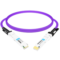
With the continuous expansion of data centers and the increasing demand for high-performance computing, the AEC (Active Electrical Cable) has emerged as an effective high-speed, short-distance transmission solution. Major cloud service providers—such as Google, AWS, and Microsoft—have already embarked on large-scale deployments of AEC, while hardware manufacturers like Nvidia have integrated it extensively into their data center architectures. Compared to traditional Active Optical Cables (AOC) and optical modules, AEC boasts lower costs and reduced power consumption, making it particularly competitive for short-range transmission scenarios, especially when constructing large-scale AI clusters. Moreover, by integrating a retimer chip, AEC active copper cables effectively compensate for signal attenuation and distortion, thereby enabling longer transmission distances and higher bandwidth. These technical merits establish AEC as a key enabler for high-speed, short-range connectivity within data centers.
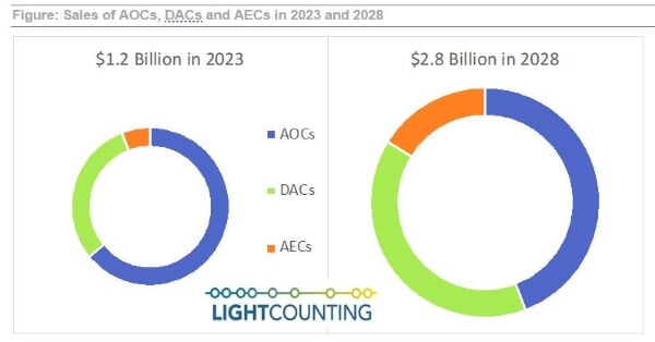
According to market research forecasts, the AEC market is poised for rapid growth in the coming years. It is anticipated that the market will reach approximately USD 2.8 billion by 2028, with a compound annual growth rate (CAGR) of 45% between 2023 and 2028. The brisk expansion has prompted numerous DAC (Direct Attach Copper) and optical module manufacturers to invest in the design and production of AEC products. However, the varying investment strategies and subsequent product introductions have presented these manufacturers with unprecedented challenges in design and testing.
As a professional provider of testing solutions, FiberMall aims to offer nuanced testing insights and assistance to manufacturers across various sectors as they integrate AEC. Their goal is to facilitate a smoother transition of AEC products from production testing to practical application.
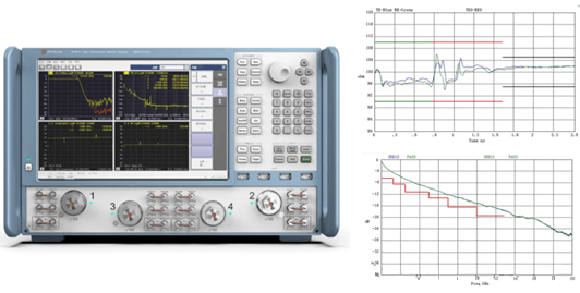
Traditional DAC manufacturers have long employed S-parameter methodologies to assess high-frequency parameters, such as insertion loss (IL), return loss (RL), time-domain reflectometry (TDR), and crosstalk, which prove invaluable for passive DACs. However, when extended copper cables incorporate retimer or DSP chips, the measurement process becomes digital, causing S-parameters to lose their effectiveness as benchmarks for analog product frequency-domain characteristics. This shift necessitates a transition from passive or analog measurement techniques to those suitable for digital products—a change that may benefit from adopting testing methodologies currently used for optical modules or AOC. That said, manufacturers specializing in optical modules or AOC, who have traditionally focused on resolving challenges in optoelectronic conversion and DSP digitalization, might not be fully equipped to handle issues such as solder joint stability, impedance variations, and crosstalk in copper cables before or after the DSP or retimer stages. Consequently, evolving from digital optoelectronic measurements to those for purely copper-based digital products presents a significant challenge.
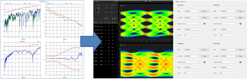
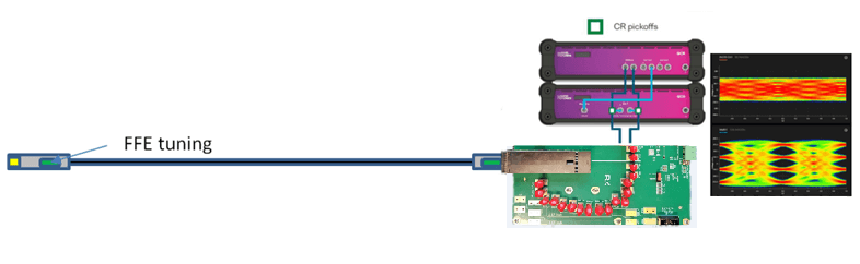
Moreover, the shift from DAC to AEC means that conventional network analyzers are no longer suitable for measurements involving retimer- or DSP-based systems. Instead, testing methodologies must now incorporate instruments such as digitizing oscilloscopes and bit error rate testers (BERTs) to observe the electrical eye diagram at the receiver (Rx) end and verify compliance with IEEE specifications. In this context, the digital equalization adjustments—such as the feed-forward equalization (FFE) associated with retimers or DSPs—must now be calibrated based on Rx electrical eye diagrams. Unlike in fiber-based systems, where an optical eye diagram is prevalent, the electrical eye diagram in copper cable transmission is subject to complications like crosstalk and impedance discontinuities, which diminish its clarity. Consequently, FFE adjustments must be conducted through comprehensive testing at various points along the cable rather than relying solely on traditional optical criteria.
In summary, ensuring the quality of AEC requires a systematic, multi-dimensional testing approach—encompassing configurations such as host-to-line, line-to-line, line-to-host, and host-to-host tests—in order to effectively adjust and optimize the equalization compensation provided by the DSP or retimer. This rigorous testing strategy is fundamental to guaranteeing the robust performance and reliability of AEC systems.
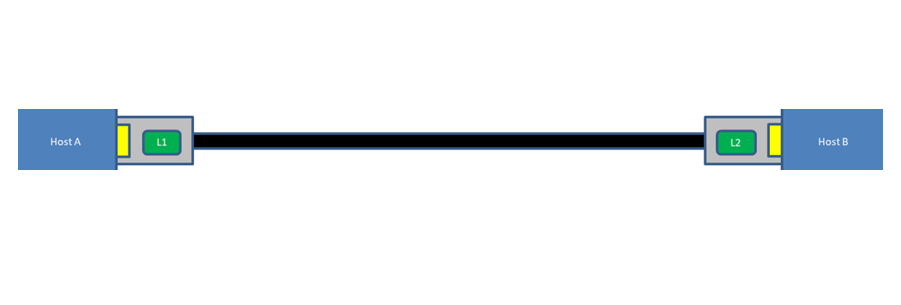
- Host A to L1: It is essential to ensure that the gold finger connector’s insertion loss and impedance conform to the required specifications. To achieve this, the MCB test board must meet the IEEE standards for both impedance and insertion loss. Moreover, the signal generated by the simulated host must comply with IEEE standards, and the bit error rate (BER) on the line side should be verified to be several orders of magnitude below the specified threshold.
- L1 to L2: The DSP or retimer must generate a pseudo-random binary sequence (PRBS) at this stage. Appropriate adjustments to the feed-forward equalization (FFE) are necessary to ensure that the signal-to-noise ratio (SNR) and BER on the receiving line are optimal. Often, the DSP or retimer chips include link-training functions that facilitate the calibration of the FFE between lines; however, the effectiveness of these adjustments is subject to various conditions. Thus, the line-to-line SNR and BER serve as key references for achieving a balanced final adjustment. Here, the FFE calibration is designed specifically to compensate for the characteristics of the copper cable while taking into account the receiver’s adaptive capabilities.
- Host A to L2: With the additional loss incurred in the Host A-to-L1 connection, it is necessary to perform BER and SNR measurements at L2. These measurements help to further validate that the adjustments made to the DSP’s FFE or the receiver’s continuous time linear equalizer (RX CTLE) are adequate, and they indicate whether further compensation is required.
- L1 to Host B: Similar to the Host-to-Line scenario, it is critical to ensure that the insertion loss and impedance of the Rx-side gold finger connectors meet the requirements. An electrical sampling oscilloscope, with its LFE calculation functionality, can be employed to perform FFE tuning for the AEC DSP. Particular attention must be given to observing post-adjustment changes in the eye diagram, such as whether the eye height is sufficiently large, as well as variations in eye width and skew. These changes indicate whether the DSP’s equalization adjustments can adequately address issues such as cable reflections and crosstalk, since the process now involves more than simple insertion loss compensation. Naturally, the BER remains an important parameter and may be used in conjunction with the line-to-line FFE results for fine tuning. The eye diagram measurements in this stage may be performed using either a DSP single-channel clock trigger or an external clock data recovery (CDR) circuit.
- Host A to Host B: After verifying the DSP’s FFE performance at various points, a comprehensive host-to-host test may be conducted. This test is not limited to evaluating BER but also includes assessments of forward error correction (FEC), eye diagram parameters, and other critical metrics. Ideally, such tests should be performed using actual or simulated switch test equipment, which can provide detailed insights regarding parameters such as BER, SNR, eye diagram characteristics, and the receiver’s equalization values. It is important to note that due to the signal reconditioning performed by the DSP/retimer, the host’s native clock may not satisfy measurement requirements; hence, a CDR-extracted clock should be used during the eye diagram test.
In addition, it is important to recognize that AEC systems exist in various architectural configurations—including 800G-to-800G, Gearbox, PRBS combined with MSB/LSB modes, and single-retimer structures. Each configuration necessitates a unique testing approach.
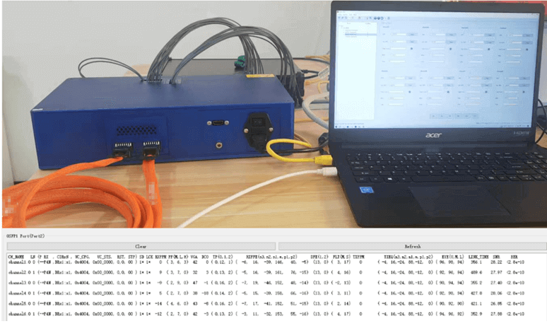
FiberMall offers a comprehensive suite of testing solutions for AEC, which facilitates the rapid integration of new products by AEC manufacturers. For instance, the 8X00 series LPO bit error rate tester can simulate a host transmitter and, analogous to a TH5 host receiver, measure parameters such as BER, FEC, SNR, and link time. With over 40 dB of receiver equalization capability, it can conduct AEC BER measurements in single-sided retimer/DSP architectures while preventing loss-of-lock conditions. In addition, the MCBs designed for the QDD800, OSFP1.6T/800, and QSFP112 platforms can accommodate AEC measurements across multiple architectural configurations (e.g., QDD <-> 2 QSFP). Furthermore, the combination of the QCA1002 electrical sampling oscilloscope and the QCR 1002 electrical clock data recovery instrument—comparable to leading brand offerings—enables AEC manufacturers to optimize FFE accurately at a lower cost and with reduced tuning time, while rapidly identifying the optimal tap configuration and assessing crosstalk conditions via eye diagram measurements. Finally, the 67 GHz SP867P vector network analyzer (VNA) can swiftly detect passive issues related to impedance and insertion loss.
Related Products:
-
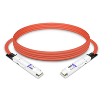
 OSFP-800G-AEC50CM 0.5m (1.6ft) 800G OSFP to OSFP PAM4 Active Electrical Copper Cable
$875.00
OSFP-800G-AEC50CM 0.5m (1.6ft) 800G OSFP to OSFP PAM4 Active Electrical Copper Cable
$875.00
-
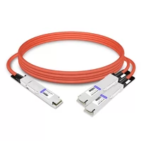
OSFP-800G-AEC3M 3m (10ft) 800G OSFP to OSFP PAM4 Active Electrical Copper Cable
$975.00
-
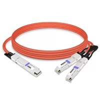
OSFP8-2OSFP4-AEC50CM 0.5m (1.6ft) 800G OSFP to 2x400G OSFP Breakout Active Electrical Cable
$1050.00
-
OSFP8-2OSFP4-AEC3M 3m (10ft) 800G OSFP to 2x400G OSFP Breakout Active Electrical Cable
$1300.00
-
OSFP8-2QSFP112-AEC50CM 0.5m (1.6ft) 800G OSFP to 2x400G QSFP112 Breakout Active Electrical Cable
$1375.00
-
OSFP8-2QSFP112-AEC3M 3m (10ft) 800G OSFP to 2x400G QSFP112 Breakout Active Electrical Cable
$1500.00
-
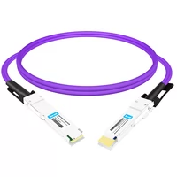
QDD-OSFP-FLT-AEC50CM 0.5m (1.6ft) 400G QSFP-DD to OSFP Flat Top PAM4 Active Electrical Copper Cable
$1200.00
-
QDD-OSFP-FLT-AEC3M 3m (10ft) 400G QSFP-DD to OSFP Flat Top PAM4 Active Electrical Copper Cable
$1700.00