Introduction
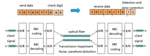
Optical networks require the use of Forward Error Correction (FEC) to guarantee reliable communication. Similar to how a reader may overlook a single spelling mistake in a text but struggle when errors accumulate, digital transmissions—encoded as sequences of “0”s and “1”s—are subject to inevitable signal attenuation and bit errors. FEC is defined as the capability of a communication system to maintain error-free transmission despite the presence of noise and other impairments. Essentially, FEC is a process that encompasses both encoding and decoding; the encoder at the transmitter appends algorithmically generated redundancy to the data, and by applying the corresponding decoding algorithm at the receiver, individual bit errors can be detected and corrected without the need for retransmission.
Causes of Transmission Errors in Optical Networks
There are several factors that may lead to transmission errors in an optical network:
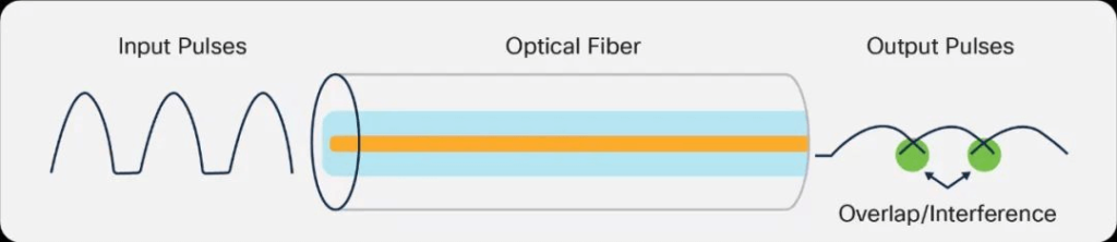
Inter-Symbol Interference (ISI): Both multimode and single-mode optical fibers exhibit dispersion, which can distort the transmitted pulses during propagation. This distortion may cause pulses to overlap, resulting in inter-symbol interference and increased error rates.
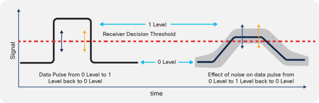
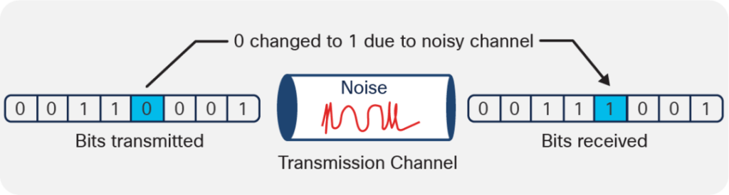
Signal-to-Noise Ratio (SNR) Degradation: During both transmission and detection, the combined effects of optical dispersion and electronic noise can degrade the quality of the input pulses. For instance, noise spikes at the sampling points may cause a single transmitted pulse to be misinterpreted as either a “1” or a “0.”
Data Corruption: Errors may also occur if data corruption is induced during transmission, such as by parallel transmission noise, which can lead to the incorrect interpretation of individual bits at the receiver.
The Principle of Forward Error Correction (FEC)
Optical networks rely on fiber-optic cables to transmit data using light signals, particularly over long distances and at high data rates (such as 100G and 400G). During transmission, factors like signal attenuation, dispersion (including chromatic dispersion and polarization mode dispersion), and noise can elevate the bit error rate (BER) and compromise data integrity.

FEC is a digital signal processing technique designed to address this issue by adding redundant information, known as error correction codes, to the transmitted data stream. Since the FEC decoder uses only the redundant bits to detect and correct errors, it avoids the need to retransmit an entire erroneous frame and thereby preserves bandwidth.
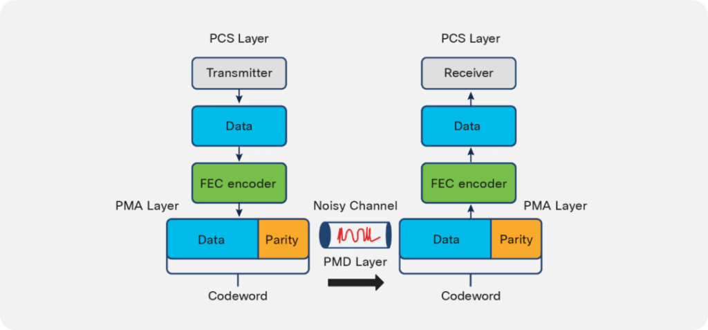
An FEC code is usually specified as an ordered pair (n, k), where k represents the number of payload symbols and n indicates the total length of the code word. The code word comprises a data block of k symbols and an additional parity block of n–k symbols that contains both parity bits and redundant information. At the transmitter, the FEC encoder employs a complex polynomial function to oversample the data block, generating an error polynomial. At the receiver, error detection and correction are carried out by computing a “syndrome” from the received code word; a zero syndrome indicates that the transmission was error-free.
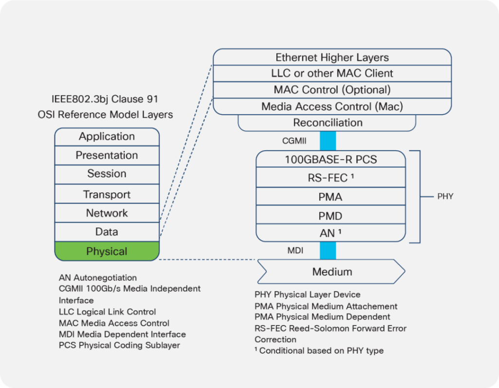
In network architecture, the FEC layer is positioned between the Physical Coding Sublayer (PCS) and the Physical Medium Attachment (PMA) layer. The PCS is responsible for mapping the raw data bits into code groups suitable for transmission, while the PMA layer relays the symbol stream to or from the actual transceiver.
Common FEC Schemes
Two FEC schemes commonly used in optical communications are: RS-FEC (528, 514) and RS-FEC (544, 514).
The RS(544,514) FEC scheme is typically employed for 400G PAM4 and 100G PAM4 (CAUI-2) modulation, whereas RS-FEC (528,514) is generally used for 100G NRZ modulation. In RS-FEC(528,514), the encoding process begins with a data field consisting of 514 symbols (with each symbol typically 10 bits in length), after which 14 parity symbols are added to form a 528-symbol code word. In contrast, the RS-FEC (544,514) scheme adds 30 parity symbols to create a 544-symbol code word. Because PAM-4 signals have more closely spaced voltage levels, resulting in an eye diagram with an amplitude roughly one-third that of an NRZ signal, they are more susceptible to noise and necessitate additional redundancy. To compensate for the lower SNR of PAM-4 signals, KP-FEC is designed to achieve a higher coding gain; it can correct up to 15 symbol errors per code word, while KR-FEC is limited to correcting up to 7 symbol errors.
FEC Implementation in 100G and 400G Optical Modules
The necessity for FEC and the type of FEC implemented in an optical module depends on the module’s operating mode and standard.
100G Optical Modules
For 100G optical modules, the FEC configuration is determined by the modulation format (NRZ or PAM4):
| Module Type | FEC | Remarks |
| 100GBASE-SR4 | Not Required | Short distance; 100 m (OM4 fiber) |
| 100GBASE-LR4 | Not Required | 10 km; LAN-WDM |
| 100GBASE-ER4 | Not Required | 30 km; utilizes high-sensitivity APD |
| 100G CWDM4 | RS(528,514) | 2 km; NRZ modulation |
| 100G PSM4 | RS(528,514) | 500 m; NRZ modulation |
| 100GBASE-DR (PAM4) | Built-in FEC | 500 m; single-wavelength PAM4 |
| 100GBASE-FR (PAM4) | Built-in FEC | 2 km; single-wavelength PAM4 |
| 100GBASE-LR (PAM4) | Built-in FEC | 10 km; single-wavelength PAM4 |
400G Optical Modules
400G optical modules are predominantly based on PAM4 modulation. Given their high data rate and heightened susceptibility to noise, FEC is generally enabled by the host. Common standards in this category include 400GBASE-DR4, 400GBASE-FR8, 400GBASE-LR8, and 400GBASE-SR8:
| Module Type | FEC | Remarks |
| 400GBASE-DR4 | RS(544,514) | 500 m; configured as 4×100G using PAM4 |
| 400GBASE-FR8 | RS(544,514) | 2 km; configured as 8×50G using PAM4 |
| 400GBASE-LR8 | RS(544,514) | 10 km; configured as 8×50G using PAM4 |
| 400GBASE-SR8 | RS(544,514) | Utilizes multimode fiber; 8×50G using PAM4 |
| 400G ZR/ZR+ | Other FEC (Soft Decision FEC) | Long distance; coherent modules (refer to vendor documentation) |
Further Considerations
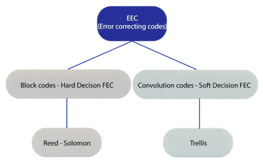
Advances in FEC continue to play a pivotal role in supporting ever-increasing data rates and longer transmission distances in optical networks. In addition to traditional RS-FEC approaches, research into soft decision FEC schemes and innovative iterative decoding algorithms is expanding the boundaries of error correction performance. These developments help counteract signal impairments in coherent transmission systems and further enhance overall network reliability.
Exploring the trade-offs between coding gain, overhead, and complexity remains a vital aspect of designing next-generation optical communication systems—a topic that continues to garner significant attention in both research and industry.
Related Products:
-
 QSFP28-100G-SR4 100G QSFP28 SR4 850nm 100m MTP/MPO MMF DDM Transceiver Module
$40.00
QSFP28-100G-SR4 100G QSFP28 SR4 850nm 100m MTP/MPO MMF DDM Transceiver Module
$40.00
-
QSFP28-100G-IR4 100G QSFP28 IR4 1310nm (CWDM4) 2km LC SMF DDM Transceiver Module
$110.00
-
QSFP28-100G-DR1 100G QSFP28 Single Lambda DR 1310nm 500m LC SMF with FEC DDM Optical Transceiver
$180.00
-
QSFP28-100G-PSM4 100G QSFP28 PSM4 1310nm 500m MTP/MPO SMF DDM Transceiver Module
$180.00
-
QSFP28-100G-FR1 100G QSFP28 Single Lambda FR 1310nm 2km LC SMF with FEC DDM Optical Transceiver
$215.00
-
QSFP28-100G-LR4 100G QSFP28 LR4 1310nm (LAN WDM) 10km LC SMF DDM Transceiver Module
$285.00
-
QSFP28-100G-LR4-20 100G QSFP28 LR4 1310nm LWDM4 20km LC SMF DDM Transceiver Module
$300.00
-
QSFP-DD-400G-SR8 400G QSFP-DD SR8 PAM4 850nm 100m MTP/MPO OM3 FEC Optical Transceiver Module
$149.00
-
QSFP-DD-400G-DR4 400G QSFP-DD DR4 PAM4 1310nm 500m MTP/MPO SMF FEC Optical Transceiver Module
$400.00
-
QSFP-DD-400G-SR4 QSFP-DD 400G SR4 PAM4 850nm 100m MTP/MPO-12 OM4 FEC Optical Transceiver Module
$450.00
-
QSFP-DD-400G-FR4 400G QSFP-DD FR4 PAM4 CWDM4 2km LC SMF FEC Optical Transceiver Module
$500.00
-
QSFP-DD-400G-ER4 400G QSFP-DD ER4 PAM4 LWDM4 40km LC SMF without FEC Optical Transceiver Module
$3500.00
-
QSFP-DD-400G-ER4L 400G QSFP-DD ER4 Lite 30km LWDM4 LC SMF with FEC Optical Transceiver Module
$3000.00
-
QSFP-DD-400G-LR4 400G QSFP-DD LR4 PAM4 CWDM4 10km LC SMF FEC Optical Transceiver Module
$600.00