
How far can CWDM transmit? The answer depends on the data rate, operating wavelength, optical power budget, fiber characteristics, and passive component losses.
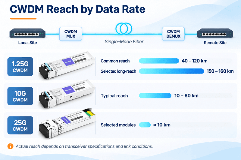
Typical CWDM transceiver specifications cover a wide range of distances. At 10G, shorter-wavelength modules are commonly rated for 10 to 40 km, while selected longer-wavelength modules support up to 80 km. At 1.25G, long-reach CWDM SFP modules can support 120 km, with some specialized models rated for 150 to 160 km.
These distances are not universal limits. They are product-specific ratings based on defined optical and transmission conditions.
Consider an 80 km CWDM link. A transceiver may be rated for 80 km in a point-to-point connection, but adding a pair of CWDM MUX/DEMUX units can consume several additional decibels of optical power. The same module may then fail to provide sufficient margin.
This guide explains how CWDM transmission distance is determined. It covers typical reach by data rate and wavelength, ITU-T application classifications, three practical link-budget examples, chromatic dispersion, and the options available when a fiber span exceeds the supported reach.
Key Takeaways
- CWDM does not have one universal maximum distance. Typical 10G modules support approximately 10 to 80 km, while selected 1.25G modules can reach 120 to 160 km.
- Wavelength affects fiber attenuation and chromatic dispersion. Standard G.652 fiber generally has lower attenuation around 1550 nm than around 1310 nm.
- At higher data rates, chromatic dispersion and transmitter characteristics become increasingly important.
- MUX/DEMUX insertion loss reduces the available optical power budget. Always calculate the complete link rather than relying on the transceiver’s advertised distance.
- Standard C-band EDFAs cannot amplify all 18 wavelengths in the conventional CWDM grid.
CWDM Distance by Data Rate and Wavelength Band
CWDM transmission distance depends primarily on the optical characteristics of the transceiver and the fiber link. Data rate and wavelength are two important factors.
The following table summarizes common commercial transceiver reach categories. These are representative product ratings, not guaranteed system distances.
| Data Rate | 1271–1451 nm | 1471–1611 nm | Main Considerations |
| 1.25G | 40–120 km | 80–160 km | Optical power budget |
| 10G | 10–40 km | 40–80 km | Optical loss and dispersion |
| 25G | Around 10 km on selected products | Product-specific | Optical budget and transceiver design |
The actual reach depends on the specific module. Some 1.25G CWDM modules support 120 km even on shorter-wavelength channels, so these wavelength groups should not be treated as absolute distance categories.
1.25G: The Long-Reach Workhorse
Gigabit CWDM is well suited to long-distance transmission because its lower data rate generally makes chromatic dispersion less restrictive.
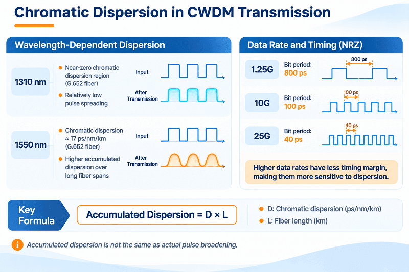
The bit period at 1.25G is approximately 800 ps, significantly longer than the 100 ps bit period of a 10G NRZ signal. This provides more tolerance for pulse broadening under otherwise comparable conditions.
Commercial 1.25G CWDM SFP modules are available in 20, 40, 80, and 120 km versions. Selected high-budget models can reach 150 to 160 km.
For example, FiberMall offers a 1.25G CWDM SFP operating at 1550 nm with a rated reach of 120 km.
Its published optical specifications include:
- Minimum TX power: 0 dBm
- Receiver sensitivity: -32 dBm
- Optical power budget: 32 dB
See the 1.25G 1550 nm CWDM SFP 120 km.
A 160 km rating requires a specific high-budget transceiver and a carefully engineered optical path. It should not be assumed that every 1.25G CWDM module can achieve this distance.
10G: Two Different Links in One Grid
10G CWDM transmission is more demanding because both optical power budget and chromatic dispersion must be considered.
Shorter-wavelength channels, particularly those near 1310 nm, generally experience higher attenuation than channels around 1550 nm. However, chromatic dispersion is relatively low near the zero-dispersion region of standard single-mode fiber.
Longer-wavelength channels can offer lower attenuation, but dispersion generally increases as the operating wavelength moves farther from the zero-dispersion region.
Typical commercial examples include:
- 1270 nm 10G CWDM SFP+: 40 km.
- 1470 nm 10G CWDM SFP+: 80 km.
For example, FiberMall’s 1470 nm 80 km CWDM SFP+ uses an EML transmitter and an APD receiver.
Its published specifications include:
- TX power: 0 to +4 dBm
- Receiver sensitivity: -23 dBm
- Optical power budget: 23 dB
See the 10G CWDM SFP+ 1470 nm 80 km.
These are transceiver ratings, not guaranteed distances through every CWDM MUX/DEMUX configuration. The actual optical budget and dispersion tolerance must be checked before deployment.
25G: O-Band Only, About 10 km
25G CWDM modules, typically using the SFP28 form factor, are commonly available with 10 km reach specifications.
Some commercial product families support six CWDM wavelengths:
1271, 1291, 1311, 1331, 1351, and 1371 nm.
These wavelengths span both the O-band and E-band. Therefore, describing the entire 1271–1371 nm range as O-band is not technically accurate.
The use of wavelengths near 1310 nm is beneficial because standard G.652 fiber has its zero-dispersion wavelength in this region.
This helps control chromatic dispersion, although the actual link performance still depends on the transmitter, receiver, optical power budget, and fiber characteristics.
There is also an important distinction between commercial product ratings and standardized applications. ITU-T G.695 (05/2025) classifies a four-channel NRZ 25G short-haul application with a 2 km target distance. This is not a universal limit for every commercial 25G CWDM SFP28 module.
Always check the specific transceiver datasheet rather than assuming all 25G CWDM products have the same wavelength configuration or reach.
What the Standards Say
ITU-T G.695 defines optical interface parameters and application classifications for CWDM transmission systems.
The current edition, ITU-T G.695 (05/2025), covers CWDM applications with up to 16 channels and data rates up to 100 Gbit/s.
It includes both unidirectional and bidirectional applications, with different optical interface requirements.
The following table shows representative G.695 application classifications.
| Application Code | Configuration | Target Distance |
| B-C4L1-0D2 | 4-channel bidirectional, NRZ 1.25G, G.652 | 90 km |
| B-C4L1-1D2 | 4-channel bidirectional, NRZ 2.5G, G.652 | 80 km |
| B-C8L1-0D2 | 8-channel bidirectional, NRZ 1.25G, G.652 | 64 km |
| C8L1-1D2 | 8-channel unidirectional, NRZ 2.5G, G.652 | 55 km |
| C4L1-2D1 | 4-channel unidirectional, NRZ 10G, G.652 | 40 km |
| B-C8L1-2D2F | 8-channel bidirectional, NRZ 10G, G.652, FEC | 55 km |
G.695 also includes a four-channel NRZ 25G short-haul application, C4S1-9D1F, with a 2 km classification distance.
These distances are classification values, not guaranteed reach specifications for every commercial transceiver.
The application code identifies several important characteristics, including channel count, span class, data rate, fiber type, transmission direction, and whether FEC is required.
For engineering reference, consult the latest ITU-T G.695 recommendation.
Why CWDM Distance Is Not One Number
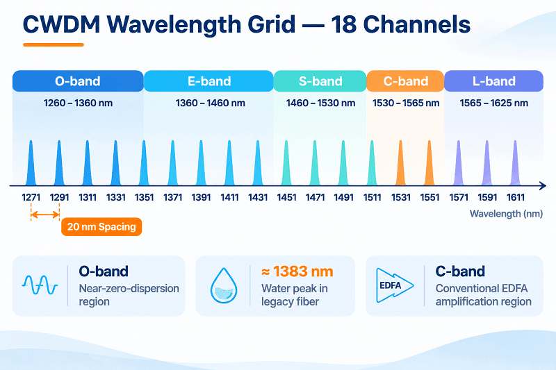
The conventional CWDM wavelength grid defined by ITU-T G.694.2 contains 18 nominal channels, spaced 20 nm apart, from 1271 nm to 1611 nm.
However, standard single-mode fiber does not have the same attenuation and dispersion characteristics across this entire wavelength range.
Wavelength Bands and Fiber Attenuation
The commonly used optical wavelength bands are:
| Band | Wavelength Range |
| O-band | 1260–1360 nm |
| E-band | 1360–1460 nm |
| S-band | 1460–1530 nm |
| C-band | 1530–1565 nm |
| L-band | 1565–1625 nm |
The 18-channel CWDM grid crosses all five wavelength bands.
For standard G.652 single-mode fiber, attenuation is generally lower around 1550 nm than around 1310 nm.
ITU-T G.652.D specifies maximum cable attenuation of 0.40 dB/km from 1310 to 1625 nm and 0.30 dB/km in the 1530–1565 nm region.
These are specification limits, not the actual attenuation of every installed fiber link.
The following table summarizes the main design considerations.
| Channels | Wavelengths | Main Characteristics | Design Considerations |
| 1–4 | 1271–1331 nm | O-band | Low dispersion near 1310 nm; relatively higher attenuation |
| 5–10 | 1351–1451 nm | O/E-band | Check attenuation near the water peak |
| 11–13 | 1471–1511 nm | S-band | Verify wavelength-specific fiber loss |
| 14–15 | 1531–1551 nm | C-band | Generally favorable fiber attenuation |
| 16–18 | 1571–1611 nm | L-band | Check macrobending and wavelength-dependent loss |
Two additional considerations are important.
First, older single-mode fiber may have a pronounced water peak around 1383 nm. This can increase attenuation for CWDM channels near 1371 nm and 1391 nm. The impact on adjacent channels depends on the actual fiber attenuation spectrum.
Modern G.652.D fiber includes low-water-peak characteristics that reduce this problem.
Second, longer wavelengths are generally more sensitive to macrobending losses. This is particularly important on older fiber routes with tight bends, poor cable management, or excessive microbending.
For an existing fiber network, measure the link at the intended CWDM wavelength rather than assuming that a 1310 nm measurement represents the entire CWDM grid.
The Three Limits That Set CWDM Reach
CWDM transmission distance is determined by three main engineering factors: optical power budget, chromatic dispersion, and amplification capability.
Their relative importance varies with the data rate, wavelength, transceiver design, and fiber conditions.
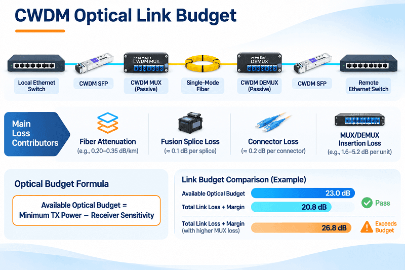
1. Optical Power Budget
The optical power budget is the difference between the minimum guaranteed transmitter output power and the receiver sensitivity.
Optical Power Budget = Minimum TX Power − Receiver Sensitivity
The total link loss includes:
- Fiber attenuation
- Fusion splice losses
- Connector insertion losses
- CWDM MUX/DEMUX insertion losses
- Additional passive component losses
An engineering margin must also be reserved to account for variations and future changes.
A transceiver rated for 80 km may work on a low-loss point-to-point link but fail when additional MUX/DEMUX losses consume the available budget.
2. Chromatic Dispersion
Chromatic dispersion causes different wavelength components of an optical signal to travel at different group velocities.
This broadens optical pulses and can introduce inter-symbol interference.
At 1.25G, dispersion is generally less restrictive because the bit period is longer.
At 10G and 25G, the available timing margin is smaller, so the transmitter’s spectral characteristics, chirp, receiver design, and any supported equalization or FEC become more important.
3. Optical Amplification
Standard erbium-doped fiber amplifiers (EDFAs) are designed primarily for the C-band, typically around 1530–1565 nm.
Only CWDM channels falling within the amplifier’s supported gain range can benefit from a conventional C-band EDFA.
The conventional 18-channel CWDM grid spans 1271–1611 nm, so a standard C-band EDFA cannot amplify the entire grid.
Specialized amplification solutions may support wider wavelength ranges, but they require dedicated optical system design.
This is one reason CWDM and DWDM have different amplification and long-haul transmission characteristics.
The Link Budget, Worked at 40, 80, and 120 km
A CWDM link budget should use the actual transceiver specifications and measured fiber loss.
The following examples use published FiberMall transceiver specifications and representative passive-component losses to demonstrate how the calculations work.
The fiber-loss values are assumed measured values for the example routes, not universal attenuation figures.
For the MUX/DEMUX calculations, assume a representative dual-fiber CWDM MUX specification:
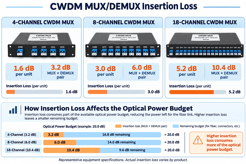
- 4-channel insertion loss: up to 1.6 dB per unit.
- 8-channel insertion loss: up to 3.0 dB per unit.
The MUX and DEMUX pair therefore contributes up to 3.2 dB for a 4-channel system or 6.0 dB for an 8-channel system, before separately counted connector losses.
Actual values must be taken from the selected equipment datasheets.
10G, 40 km, Short Wavelength, 4-Channel MUX
Consider a 1270 nm 10G CWDM SFP+ with the following specifications:
| Item | Value |
| Minimum TX power | 0 dBm |
| Receiver sensitivity | -16 dBm |
| Available optical budget | 16.0 dB |
| Measured fiber loss | 10.8 dB |
| Splices, 5 × 0.1 dB | 0.5 dB |
| Connectors, 4 × 0.2 dB | 0.8 dB |
| 4-channel MUX + DEMUX | 3.2 dB |
| Engineering margin | 3.0 dB |
| Total required budget | 18.3 dB |
| Remaining margin | -2.3 dB |
Result: The link does not close with the assumed MUX/DEMUX configuration.
Without the MUX/DEMUX pair, the total requirement would be 15.1 dB, leaving only 0.9 dB beyond the reserved engineering margin.
This demonstrates why a 40 km transceiver rating does not automatically guarantee a 40 km CWDM transport link through passive multiplexing equipment.
The specific 1270 nm 40 km 10G CWDM SFP+ specifications should be checked before deployment.
10G, 80 km, Long Wavelength, 8-Channel MUX
Consider a 1470 nm 10G CWDM SFP+.
Its published specifications are:
| Item | Value |
| Minimum TX power | 0 dBm |
| Receiver sensitivity | -23 dBm |
| Available optical budget | 23.0 dB |
| Measured fiber loss | 16.0 dB |
| Splices, 10 × 0.1 dB | 1.0 dB |
| Connectors, 4 × 0.2 dB | 0.8 dB |
| 8-channel MUX + DEMUX | 6.0 dB |
| Engineering margin | 3.0 dB |
| Total required budget | 26.8 dB |
| Remaining margin | -3.8 dB |
Result: The link does not close with the assumed 8-channel MUX/DEMUX configuration.
Without the MUX/DEMUX pair, the link would require 20.8 dB, leaving 2.2 dB beyond the engineering margin.
The additional insertion loss from the MUX/DEMUX pair changes the result significantly.
This is why the optical power budget must be calculated for the complete transmission path, not just the transceiver pair.
1.25G, 120 km, Long Wavelengths, 4-Channel Mux
A 1550 nm 1.25G CWDM SFP can provide a much larger optical power budget.
Consider the following specifications:
| Item | Value |
| Minimum TX power | 0 dBm |
| Receiver sensitivity | -32 dBm |
| Available optical budget | 32.0 dB |
| Measured fiber loss | 23.0 dB |
| Splices, 10 × 0.1 dB | 1.0 dB |
| Connectors, 4 × 0.2 dB | 0.8 dB |
| 4-channel MUX + DEMUX | 3.2 dB |
| Engineering margin | 3.0 dB |
| Total required budget | 31.0 dB |
| Remaining margin | 1.0 dB |
Result: The link closes under the assumed conditions, with 1.0 dB remaining beyond the reserved engineering margin.
This example uses a measured fiber loss of 23 dB over 120 km at the selected wavelength. It should not be treated as a default value for every 1550 nm fiber route.
The 1550 nm 120 km 1.25G CWDM SFP provides a suitable product reference.
The important lesson is that even a high-budget 1.25G transceiver requires careful engineering when the fiber span is long and passive components are included.
Measure the Span Before You Trust the Budget
A datasheet provides the transceiver’s optical specifications. It does not describe the actual condition of an installed fiber route.
Before ordering optics for a long CWDM link, measure the fiber and calculate the complete optical loss.
Two instruments serve different purposes:
- Optical Loss Test Set (OLTS): Uses a calibrated light source and power meter to measure end-to-end insertion loss.
- OTDR (Optical Time-Domain Reflectometer): Measures fiber length and identifies splice locations, connector events, and abnormal loss characteristics.
Where possible, perform insertion-loss testing at the actual CWDM operating wavelength.
Three measurements deserve particular attention:
1. End-to-End Insertion Loss
Measure the complete optical path, including passive components where practical. Do not rely only on a 1310 nm test when the operating wavelength is 1550 nm or another CWDM channel.
2. Splice and Connector Quality
A good fusion splice typically introduces relatively low loss, often around 0.1 dB or less. Mechanical splices and poor-quality fusion splices can introduce significantly more loss.
Connector end faces should be inspected and cleaned before testing. Contamination and damage can cause both insertion loss and reflectance problems.
3. Optical Return Loss and Reflectance
Reflectance is different from insertion loss. Poor connector interfaces can reflect optical power toward the transmitter and affect transmission performance.
Check connector quality and the return-loss requirements of the transceiver and optical components.
For long-distance CWDM links, use the actual installed fiber length, measured attenuation, splice count, connector count, and an appropriate engineering margin. Do not apply a fixed percentage increase to fiber length as a substitute for route measurement.
Dispersion: Why 10G CWDM Reach Can Be Limited
Chromatic dispersion is the reason 10G CWDM distance has a ceiling that loss alone does not explain. CWDM dispersion is ordinary chromatic dispersion; the 20 nm channel spacing changes which wavelengths you use, not the physics of how a pulse spreads.
Standard single-mode fiber adds about 17 ps/nm/km at 1550 nm. Over 80 km, that is roughly 1,360 ps/nm. At 1610 nm it is closer to 1,600 ps/nm. A 10G pulse is about 100 ps wide, and once dispersion spreads it by more than a fraction of that width, the receiver struggles to tell a one from a zero.
Module design decides how much dispersion a link can tolerate.
| Transmitter and receiver | Dispersion tolerance | Practical reach at 10G |
| DFB laser, PIN receiver | about 200 ps/nm | 10 to 30 km |
| EML laser, PIN receiver | about 800 ps/nm | about 40 km |
| EML laser, APD receiver | about 1,600 ps/nm | 70 to 80 km |
This is why two modules with the same “10G CWDM” label can have very different reach. The label describes the wavelength grid, not the optics inside.
Marcus, an ISP engineer, saw the symptom on a 78 km span. His receive power was 2.5 dB above sensitivity, well inside specification, yet the link errored at 1571 nm and ran clean at 1531 nm on the same fiber. Power was never the problem. Dispersion was, and the shorter wavelength carried less of it.
FEC and electronic dispersion compensation can buy a few extra kilometers, and some 80 km modules rely on both. They do not repeal the physics. If a span needs 120 km at 10G, plan for regeneration or a different technology.
When CWDM Distance Is Not Enough
Sometimes the optical budget does not close, or the dispersion exceeds the transceiver’s specified tolerance.
In that situation, changing to another CWDM wavelength may not be sufficient.
Four options are worth considering.
1. Reduce the Data Rate
If the application allows it, reducing the transmission rate can provide more timing margin and make longer-reach transceivers practical.
For example, a 1.25G CWDM SFP may support a 120 km span that cannot be achieved with the existing 10G transceiver pair.
This is often the simplest option when bandwidth requirements are modest.
2. Regenerate the Optical Signal
Install an intermediate 3R regenerator or OTN transponder to divide the original link into two shorter optical spans.
Each regenerated span has its own optical power budget and dispersion requirements.
This approach can extend transmission distance while preserving the required data rate.
However, it adds powered equipment, site requirements, and additional failure points.
3. Overlay DWDM in the C-band
If the existing fiber infrastructure needs additional capacity, DWDM may provide a better long-term solution.
A hybrid CWDM/DWDM architecture can combine selected CWDM and DWDM channels on the same fiber infrastructure.
However, wavelength planning is essential.
CWDM channels such as 1531 nm and 1551 nm already occupy wavelengths within the conventional C-band. These channels may overlap with planned DWDM wavelengths.
The design must account for spectral separation, filter passbands, channel isolation, insertion loss, and the availability of suitable hybrid MUX/DEMUX equipment.
See DWDM vs. CWDM for a comparison of their architectures and applications.
4. Use Coherent Optics
For 100G and higher-capacity transport links, coherent optical technology may be more appropriate.
Coherent pluggable modules such as 400ZR and 400ZR+ use advanced modulation and digital signal processing to support higher-capacity optical transmission.
They are typically deployed in DWDM systems and may require line-system amplification, depending on the distance and fiber conditions.
They are not direct replacements for conventional CWDM SFP modules. Their power consumption, thermal requirements, optical architecture, and system cost must be considered as part of the overall design.
FAQ
How far can CWDM transmit without amplification?
There is no single maximum distance for all CWDM systems.
Typical commercial examples include:
- 10G CWDM: approximately 10–80 km, depending on the module.
- 1.25G CWDM: commonly 40–120 km, with selected modules reaching 150–160 km.
- 25G CWDM SFP28: commonly 10 km on selected commercial products.
The actual distance depends on optical power budget, dispersion tolerance, fiber attenuation, and MUX/DEMUX insertion loss.
Can CWDM reach 100 km?
Yes. Selected 1.25G CWDM SFP modules support 100 km or longer transmission.
For example, FiberMall offers 1.25G CWDM SFP products rated for 120 km.
At 10G, 100 km is more challenging. A standard 80 km-rated module should not be assumed to support a 100 km span. A specifically rated long-reach solution or intermediate regeneration may be required.
Always verify the optical budget and dispersion specifications.
Why is 10G CWDM often limited to 80 km?
The 80 km figure is a common commercial transceiver rating, not a universal physical limit.
At longer distances, several factors become important:
- Accumulated fiber attenuation
- MUX/DEMUX insertion loss
- Chromatic dispersion
- Transmitter chirp and receiver performance
- Available engineering margin
Some 10G CWDM links can operate beyond 80 km with specifically designed transceivers and transmission systems, but they require detailed verification.
Does a higher-channel-count MUX reduce CWDM transmission distance?
Yes, it can.
Higher-channel-count MUX/DEMUX units may introduce more insertion loss, reducing the available optical power budget.
For example, one representative dual-fiber CWDM MUX datasheet specifies the following maximum insertion losses per unit:
| Channel Count | MUX Loss per Unit | MUX + DEMUX Pair |
| 4 channels | 1.6 dB | 3.2 dB |
| 8 channels | 3.0 dB | 6.0 dB |
| 18 channels | 5.2 dB | 10.4 dB |
These are equipment-specific examples. Actual insertion loss varies by manufacturer and product design.
Always use the specified maximum insertion loss for the selected MUX/DEMUX pair when calculating the link budget.
Can I amplify CWDM with an EDFA?
Yes, but a standard C-band EDFA does not amplify the entire conventional CWDM wavelength grid.
It generally supports wavelengths around 1530–1565 nm, covering only part of the 18-channel CWDM spectrum.
Specialized amplification solutions may support additional wavelength bands, but they require dedicated system design.
Is CWDM distance the same as CWDM4 distance?
No.
CWDM4 is a 100G optical interconnect specification that uses four optical wavelengths:
- 1271 nm
- 1291 nm
- 1311 nm
- 1331 nm
Each optical lane carries approximately 25G, and the four wavelengths are multiplexed inside the transceiver.
A conventional 100GBASE-CWDM4 module typically supports approximately 2 km over duplex single-mode fiber.
CWDM4 uses four wavelengths from the CWDM wavelength grid, but it is not the same as a conventional 18-channel CWDM transport system using external passive MUX/DEMUX equipment.
The Distance Is a Budget, Not a Label
CWDM distance is determined by the combined effects of optical power budget, chromatic dispersion, fiber characteristics, and passive component losses.
The commonly quoted 40 km and 80 km ratings are useful starting points, but they do not guarantee that the same reach will be achieved in every network.
Before specifying a CWDM link, check the minimum transmitter output power, receiver sensitivity, fiber attenuation at the operating wavelength, MUX/DEMUX insertion loss, connector and splice losses, and the required engineering margin.
For longer 10G links, also verify the transceiver’s chromatic dispersion tolerance.
Choosing a transceiver based only on its advertised distance can lead to an optical link that works under initial test conditions but has insufficient operating margin.
For additional technical guidance, see the CWDM complete guide, the CWDM MUX/DEMUX guide, and the CWDM SFP guide.
You can also review the CWDM wavelength chart to identify the available wavelength channels.
If you have a specific transmission distance, fiber type, and channel configuration, contact FiberMall’s engineering team. We can help evaluate the optical budget and recommend suitable CWDM transceivers for your application.
Related Products:
-
 Passive CWDM Double Fiber Mux & Demux Module 18 CH (1270-1610nm) LC/UPC 1U Rack
$630.00
-
Passive CWDM Double Fiber Mux & Demux Module 16 CH (1310-1610nm) 1U Rack
$570.00
-
CWDM MUX 8CH 16 Wavelengths (TX: 1310/1330/1390/1410/1470/1490/1550/1570nm RX: 1350/1370/1430/1450/1510/1530/1590/1610nm) LC/UPC Single Fiber 1U Rack
$320.00
-
Passive CWDM Double Fiber Mux & Demux Module 8CH (1470-1610nm) LC/UPC LGX BOX
$280.00
-
CWDM MUX 4CH 8 Wavelengths (TX: 1470/1490/1510/1530nm RX: 1550/1570/1590/1610nm) with Express Port LC/UPC Single Fiber LGX BOX
$150.00
-
Passive CWDM Double Fiber Mux & Demux Module 4 CH (1470-1530nm) LC/UPC LGX BOX
$150.00
-
Passive CWDM Single Fiber 1 Channel OADM LGX BOX
$70.00
-
Passive CWDM Double Fiber 2 Channels OADM LGX BOX
$130.00
-
Passive CWDM Double Fiber 4 Channels OADM LGX BOX
$250.00
-
SFP-CW10G27-40C 10G CWDM SFP+ 1270nm 40km LC SMF DDM Transceiver Module
$95.00
-
SFP-CW10G27-10C 10G CWDM SFP+ 1270nm 10km LC SMF DDM Transceiver Module
$60.00
-
SFP-CW10G59-05C 10G CWDM SFP+ 1590nm 5km LC SMF DDM Transceiver Module
$60.00
-
SFP-CW10G27-20C 10G CWDM SFP+ 1270nm 20km LC SMF DDM Transceiver Module
$75.00
-
SFP-CW10G47-100C 10G CWDM SFP+ 1470nm 100km LC SMF DDM Transceiver Module
$280.00