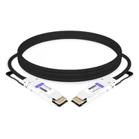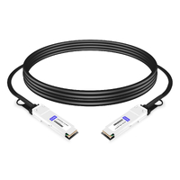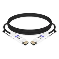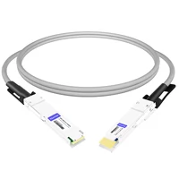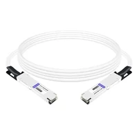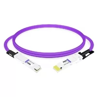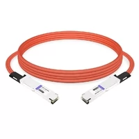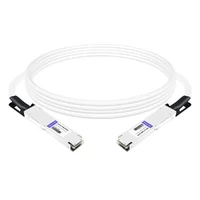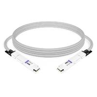

Passive and active DAC cables both transmit electrical signals over shielded twinax copper. The key difference is how they handle signal degradation. Passive DAC cables rely on the host SerDes for signal transmission and equalization, while active copper cables add signal-conditioning electronics inside the connectors. These electronics may use analog equalization (ACC) or digital retiming (AEC).
For short in-rack connections, passive DAC is usually the lowest-power and most cost-effective option. ACC and AEC extend copper reach when the electrical channel requires additional signal conditioning. AOC provides an optical alternative for longer distances or EMI-sensitive environments.
Choosing the right cable requires more than comparing maximum reach. Data rate, channel loss, host compatibility, FEC configuration, power consumption, and platform validation all matter.
Passive vs Active DAC Cable at a Glance
Passive DAC, ACC, and AEC are all copper-based interconnect solutions, but they use different signal-conditioning architectures.
| Type | Electronics | Reach Characteristics | Power Profile | Best Use |
| Passive DAC | No active signal-conditioning circuitry; EEPROM may be present | Shortest copper reach; typically up to several meters depending on speed | Lowest | Same-rack server-to-ToR links |
| ACC | Analog redriver or linear equalization circuitry | Extends reach beyond passive DAC in supported configurations | Higher than passive DAC | Short-to-medium copper connections |
| AEC | DSP retimer with clock-data recovery (CDR) | Supports longer copper connections than passive DAC in qualified designs | Higher than ACC in many implementations | AI and HPC clusters |
| AOC | Optical engines and fiber | Product-specific optical reach, often extending beyond copper | Product- and speed-dependent | Row-to-row connections and EMI-sensitive routes |
Actual reach and power consumption vary by manufacturer, cable design, data rate, host interface, and platform validation. These categories should be treated as architectural comparisons rather than universal product specifications.
What Is a Passive DAC Cable?
A passive DAC (Direct Attach Copper) cable is a shielded twinax copper assembly with transceiver-style connectors permanently attached at both ends.
It contains no active signal-conditioning circuitry. Each connector may include an EEPROM for cable identification and management information, but the EEPROM does not amplify, equalize, or retime the electrical signal.
The host SerDes drives the transmitted signal, while the receiving SerDes performs the necessary equalization. Because passive DAC does not require active signal-conditioning electronics, it offers:
- Low power consumption.
- Low component cost.
- No additional retimer processing latency.
- A simple electrical signal path.
- Minimal thermal impact.
However, passive DAC reach depends heavily on the host SerDes capability and the electrical channel’s insertion-loss budget.
A cable that works reliably in one switch or NIC platform may fail in another, even at the same data rate and length. Marginal links may also experience errors under sustained traffic or elevated operating temperatures.
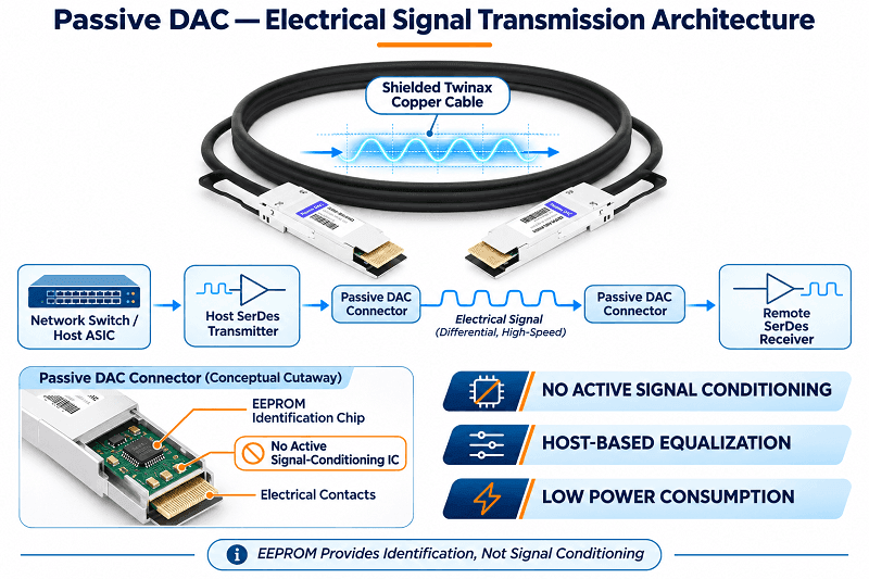
How Far Can a Passive DAC Cable Reach?
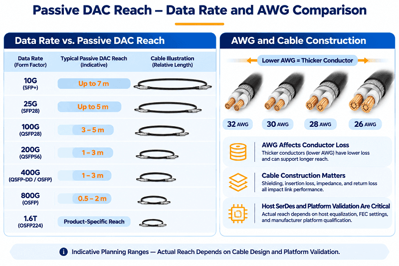
Passive DAC reach generally decreases as per-lane signaling rates increase.
Higher symbol rates increase channel bandwidth requirements and make insertion loss and signal integrity more challenging. PAM4 signaling also provides less vertical eye margin than NRZ, increasing the importance of effective equalization.
The following ranges are indicative planning references, not guaranteed maximum lengths for every platform.
| Speed and Form Factor | Typical Passive DAC Planning Range | Key Considerations |
| 10G SFP+ | 0.5–7 m | AWG and host compatibility |
| 25G SFP28 | 0.5–5 m | Cable loss class and FEC |
| 40G QSFP+ | 0.5–5 m | Four 10G electrical lanes |
| 100G QSFP28 | 0.5–5 m | CR4 electrical interface and FEC |
| 200G QSFP56 | 0.5–3 m | Four 50G PAM4 lanes |
| 400G QSFP-DD/OSFP | 0.5–3 m | Strongly dependent on cable construction and platform validation |
| 800G OSFP | 0.5–2 m | Short-reach, platform-qualified configurations |
| 1.6T OSFP224 | Product-specific | Use manufacturer-qualified cable lengths |
These ranges should not be used as substitutes for product datasheets. Always check the maximum supported cable length for the exact switch, NIC, cable SKU, and operating mode.
How AWG Affects Passive DAC Reach
AWG (American Wire Gauge) describes the conductor size. A lower AWG number indicates a thicker conductor.
Thicker conductors generally reduce conductor resistance and can help improve the electrical loss budget. However, AWG alone does not determine cable performance.
Other factors include:
- Cable construction and shielding.
- Insertion loss across the operating frequency range.
- Connector and PCB transition design.
- Differential impedance and return loss.
- Host SerDes equalization capability.
- Cable length and operating temperature.
Thicker cables can also be stiffer and more difficult to route in high-density racks.
For this reason, evaluate the complete cable assembly’s electrical performance rather than selecting a DAC based only on AWG.
When Passive DAC Is the Right Choice
Passive DAC is usually the preferred solution when the connection is short and the host platform provides sufficient electrical equalization.
Typical applications include:
- Server-to-top-of-rack (ToR) switch connections within the same rack.
- Storage-to-switch connections over short distances.
- GPU-to-switch connections where the platform validates passive copper.
- High-density deployments requiring low power consumption and low cabling costs.
- Large-scale deployments with hundreds or thousands of short interconnects.
For a 100G QSFP28 connection within the same rack, passive copper is often the most economical option.
For 400G and 800G connections, however, the available passive reach becomes more limited. Validate the complete electrical channel before ordering, particularly when cable routing, connector transitions, and host equalization affect the link budget.
A passive DAC that works at a particular length on one switch may not work reliably on another.
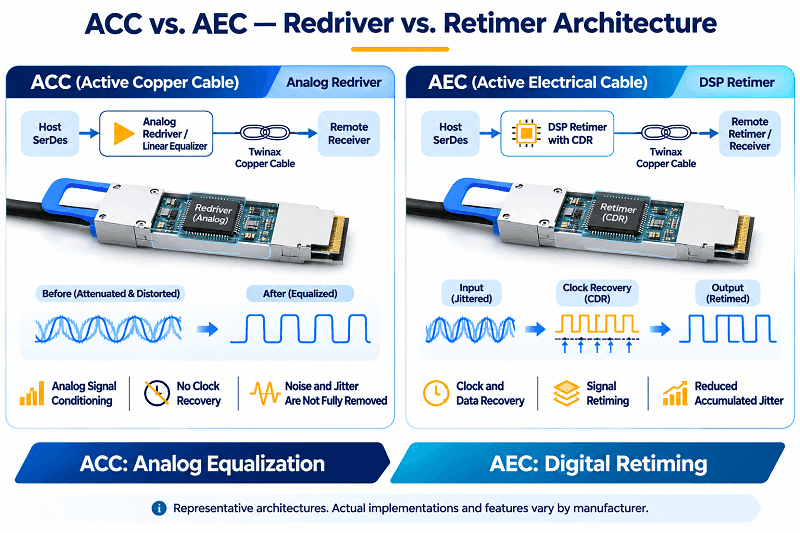
What Is an Active DAC Cable? (ACC vs AEC Explained)
An active DAC is a copper cable assembly with signal-conditioning electronics inside one or both connectors.
Unlike an AOC, the signal remains electrical throughout the copper cable. The active circuitry helps compensate for channel loss and improve signal integrity.
The two common architectures are ACC and AEC.
ACC: The Redriver Tier
ACC (Active Copper Cable) uses analog signal-conditioning circuitry, such as a redriver or linear equalizer, to compensate for electrical channel loss.
Depending on the implementation, the circuitry may amplify or reshape the incoming signal to improve the available signal margin.
Unlike a retimer, a conventional linear redriver does not perform clock-data recovery. It cannot fully remove accumulated jitter, and its performance depends on the quality of the incoming signal and the equalization design.
ACC can extend copper reach beyond passive DAC in supported configurations while generally consuming less power than a fully retimed solution.
It is useful when passive copper does not provide sufficient signal margin but a full retimer is unnecessary.
AEC: The Retimer Tier
AEC (Active Electrical Cable) uses a retimer with clock-data recovery (CDR) to recover and retime the incoming data before retransmission.
The retimer helps reduce the impact of accumulated jitter from the preceding electrical channel and generates a new electrical output signal.
Compared with passive DAC and many ACC designs, AEC can support longer copper connections and more challenging electrical channels.
However, AEC introduces additional processing latency and consumes more power because of its active retimer circuitry.
AEC is particularly useful in AI and HPC environments where high-speed connections between adjacent racks or equipment trays require more electrical reach than passive DAC can provide.
Some 400G and 800G AEC products support several-meter connections, but the maximum length must be confirmed against the specific manufacturer’s datasheet and host platform.
For a deeper explanation of electrical channel loss and signal conditioning, see FiberMall’s DAC, ACC, and AEC signal integrity guide.
Why “Active DAC” Is a Confusing Term
The term “active DAC” is often used as a general marketing description rather than a precise circuit architecture.
Some vendors use it to describe ACC, while others use it for AEC. As a result, the term alone does not tell you whether the cable contains an analog redriver or a digital retimer.
A July 2022 IEEE P802.3df Task Force terminology presentation proposed the following classifications:
- Full Active: Redriver or retimer circuitry on the transmit and receive paths at both ends.
- Half Active: Signal-conditioning circuitry on the receive path at both ends.
- Asymmetric Half Active: Signal-conditioning circuitry on both paths at one end.
These terms were proposed to improve technical communication within the task force. They should not be presented as standalone normative requirements of the published IEEE 802.3df standard.
When evaluating an active copper cable, check the manufacturer’s block diagram and datasheet for the actual signal-conditioning architecture.
Look specifically for terms such as:
- Analog redriver.
- Linear equalizer.
- DSP retimer.
- Clock-data recovery (CDR).
A redriver-based design is generally classified as ACC, while a retimed electrical cable is generally classified as AEC.
Active DAC vs. AOC
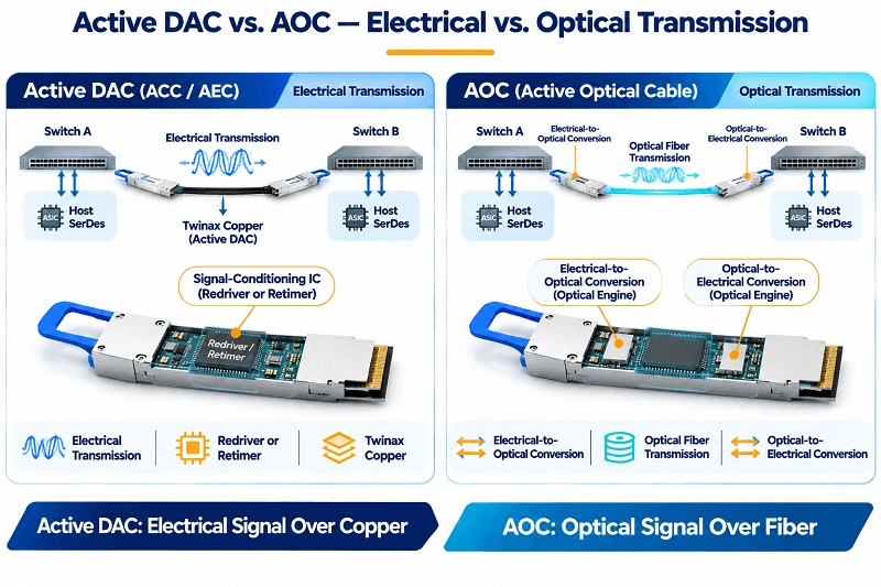
An active DAC and an AOC may look similar externally, but their internal transmission architectures are different.
An active DAC carries electrical signals through copper conductors. An AOC converts electrical signals into optical signals inside the cable assemblies and transmits data through fiber.
The optical transmission path does not conduct electromagnetic interference, making AOC suitable for environments where EMI immunity and flexible cable routing are important.
| Feature | Active DAC (ACC/AEC) | AOC |
| Transmission Medium | Copper | Optical fiber |
| Signal Type | Electrical | Optical over fiber |
| Signal Conditioning | Redriver or retimer | Electrical-optical conversion |
| EMI Susceptibility | More susceptible to EMI coupling | Optical path is immune to EMI |
| Cable Weight | Generally heavier | Generally lighter |
| Reach | Limited by electrical channel performance | Product-specific, generally longer |
| Power | Depends on ACC/AEC design | Depends on optical engines and data rate |
| Deployment | Short-to-medium copper connections | Longer connections and EMI-sensitive routes |
AOC is not universally limited to a specific distance. Available lengths depend on the data rate, optical technology, form factor, and manufacturer.
For deployments requiring replaceable optical transceivers, independent fiber patch cables may be a better choice than an integrated AOC.
See our DAC vs AOC cable comparison for a more detailed comparison.
Passive vs Active DAC: Five Differences That Matter
Reach and Signal Integrity
Reach is one of the most important factors when choosing between passive and active copper.
Passive DAC relies on the electrical performance of the host SerDes and the complete cable channel. As the channel becomes longer or more lossy, signal margin decreases.
ACC introduces analog equalization or redriver circuitry to compensate for channel loss, while AEC uses retiming to recover and regenerate the signal.
The practical difference is the available signal margin.
A passive link that works during initial testing may develop errors under sustained traffic, higher temperatures, or different platform conditions if the channel is operating too close to its electrical limits.
For this reason, cable selection should consider the complete channel rather than cable length alone.
Power and Cooling
Power consumption is an important consideration in high-density data centers.
Passive DAC generally has the lowest power requirements because it does not contain active signal-conditioning electronics. ACC and AEC require additional power for their active circuitry, while AOC powers its optical engines.
Actual consumption varies significantly by speed, form factor, and manufacturer.
The following example uses published maximum power ratings from Cisco’s 400G QSFP-DD product portfolio:
| Cable Type | Maximum Power per End | 64 Links, Both Ends |
| 400G Passive DAC | 1.5 W | 192 W |
| 400G AOC | 12 W | 1,536 W |
This example illustrates why the cable architecture can affect the overall power budget of a large deployment.
To estimate the facility-level impact, use the data center’s actual Power Usage Effectiveness (PUE):
Facility Power = IT Equipment Power × PUE
For illustration, using a PUE of 1.52:
| Cable Type | IT Power | Estimated Facility Power |
| 400G Passive DAC | 192 W | Approximately 292 W |
| 400G AOC | 1,536 W | Approximately 2.34 kW |
These figures are illustrative calculations based on the cited product ratings, not universal industry averages. Actual values depend on the selected cable SKUs and facility efficiency.
At scale, the difference in cable-end power can contribute meaningfully to rack power density and cooling requirements.
Cost and TCO
Passive DAC is generally the lowest-cost option for short connections.
ACC and AEC typically cost more because they contain additional electronic components. AOC also incorporates optical engines and fiber, while optical transceivers with separate fiber patch cables provide a different modularity and maintenance model.
However, the lowest initial purchase price does not always produce the lowest total cost.
Consider:
- Cable purchase price.
- Installation and cable management.
- Power consumption.
- Cooling requirements.
- Compatibility and qualification costs.
- Troubleshooting and replacement costs.
A passive cable that repeatedly fails platform validation may ultimately cost more than a qualified active solution.
For large deployments, compare the cost per validated working link rather than the purchase price of an individual cable.
Latency
Passive DAC does not introduce active retimer processing latency, but the cable itself still contributes propagation delay.
NVIDIA’s data center cabling guide gives an approximate cable propagation delay of 5 ns per meter, depending on the cable technology.
ACC adds signal-conditioning delay, while AEC introduces additional retimer processing latency.
Forward Error Correction (FEC) can also contribute processing latency. The actual impact depends on the FEC architecture and implementation.
For most enterprise networking applications, these differences may be small relative to the overall network path. However, they can matter in latency-sensitive environments such as high-frequency trading, certain HPC applications, and tightly coupled AI systems.
Always evaluate the complete path, including NICs, switches, FEC, and cable assemblies.
Diagnostics and Management
Passive DAC generally provides more limited diagnostics than active cable assemblies.
Its EEPROM may provide identification and management information, but passive copper does not provide optical transmit and receive power measurements.
ACC and AEC may support additional status information, lane monitoring, temperature monitoring, and diagnostic alarms depending on their management interface and implementation.
These features can help engineers identify marginal links and troubleshoot signal-integrity problems.
However, diagnostic capabilities are not universal. Check the cable’s CMIS or other applicable management specifications and the host platform’s monitoring support before assuming that a particular diagnostic feature is available.
How to Choose Between Passive and Active DAC Cable
Start with the required data rate and cable distance. Then verify host compatibility, channel loss, FEC requirements, and platform validation.
| Link Requirement | Recommended Starting Point |
| Up to 2–3 m, same rack | Passive DAC, if validated for the platform |
| 3–5 m | Qualified passive DAC, ACC, or AEC depending on the channel |
| 5–7 m | AEC where a suitable product is validated; otherwise consider AOC |
| Beyond qualified copper reach | AOC or optical transceivers with fiber |
| Longer inter-rack or row-to-row links | AOC or separate optical transceivers and fiber |
These are selection guidelines rather than guaranteed distance limits.
At 10G and 25G, passive DAC supports many short in-rack applications.
At 100G, passive copper can support several-meter links depending on the cable class, channel loss, and platform.
At 400G and 800G, passive DAC is generally a short-reach solution. ACC or AEC may be appropriate when additional copper reach is required and the platform supports the selected cable.
For 100G options, see our 100G QSFP28 DAC vs AOC guide; for 400G/800G, see the QSFP-DD cable guide.
Host and Switch Requirements
Some switches and NICs have strong per-port equalization and run passive copper reliably. Others require active cable even at short lengths. Check three things:
- EEPROM coding. The cable must identify itself in a way the switch accepts. An “unsupported transceiver” error is usually coding, not a broken cable.
- FEC support. 100G CR4 typically uses RS-FEC; some 25G links use BASE-R or RS-FEC.
- Port and breakout support. Confirm the breakout ratio and FEC mode before ordering.
Why Passive DAC Links Fail: FEC, AWG, and Cable Class
A passive DAC can train and still fail under load if the link budget is too tight for the configured FEC.
| Cable class | FEC | Typical passive length | Notes |
| CA-N | No FEC | Up to about 2 m | Lowest loss, shortest reach |
| CA-S | BASE-R or FC-FEC | About 2–3 m | Common for 25G |
| CA-L | RS-FEC | About 3–5 m | Common for 100G CR4 |
The class is encoded in the EEPROM, but vendor programming does not always match the real channel. NVIDIA’s Cumulus port documentation explains the interaction.
400G and 800G AI Clusters
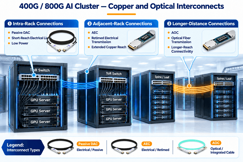
AI clusters compress the decision. A GB200 NVL72-style rack uses thousands of short copper links for scale-up, mostly passive because the distance is centimeters to a couple of meters. Industry teardowns count roughly 5,000 copper cables per rack, an illustrative figure rather than an official NVIDIA spec.
At 800G, the tiers separate cleanly:
- Passive DAC: about 1–2 m, often 0.5–1.5 m in validated NVIDIA configurations.
- ACC: about 3 m.
- AEC: about 5–7 m.
- AOC or optics: beyond copper reach, typically row-to-row.
Industry estimates put the 2026 copper mix at roughly 55–60% passive DAC, 35–40% AEC, and 5–10% ACC, with the combined DAC and AEC market growing from about $13.6 billion in 2025 to $35.7 billion by 2032. Treat these as directional. For InfiniBand-specific cabling, see our InfiniBand DAC and AEC cabling guide.
Passive vs Active DAC Cable FAQ
What is the difference between passive and active DAC cable?
A passive DAC contains no active signal-conditioning electronics and relies on the host SerDes for signal transmission and equalization.
An active DAC adds signal-conditioning circuitry inside the connector. ACC uses analog equalization or redriver technology, while AEC uses a retimer with clock-data recovery.
Passive DAC is generally cheaper and consumes less power, while active copper can support longer electrical channels.
Is active DAC better than passive DAC?
Not necessarily.
Active DAC is a reach and signal-integrity solution, not a universal upgrade.
For short in-rack links, passive DAC is usually the more cost-effective and energy-efficient choice. Active copper is useful when passive DAC cannot meet the required electrical channel margin or distance.
How far can a passive DAC cable reach?
Typical planning ranges vary by data rate:
- 10G: Up to approximately 7 m.
- 25G: Up to approximately 5 m.
- 40G: Up to approximately 5 m.
- 100G: Up to approximately 3–5 m.
- 200G: Approximately 1–3 m.
- 400G: Approximately 1–3 m.
- 800G: Approximately 0.5–2 m.
These are indicative ranges. Actual reach depends on AWG, insertion loss, host SerDes capability, FEC, and manufacturer validation.
What is the difference between ACC and AEC?
ACC uses analog redriver or equalization circuitry to compensate for signal loss without performing clock-data recovery.
AEC uses a DSP retimer with CDR to recover and retime the data before retransmission.
AEC generally supports more challenging electrical channels, but it also consumes more power and introduces additional retimer latency.
Do I need an active DAC for 5 m, 7 m, or 10 m?
It depends on the data rate and platform.
At 100G, a 5 m passive DAC may work when the cable and host are qualified for that channel.
At 7 m, ACC or AEC may be necessary, depending on the available product and electrical requirements.
At 10 m, AOC is often a more practical option for high-speed links, although some lower-speed copper implementations may support longer distances.
At 400G and 800G, do not assume that a passive DAC will work at 5 m. Check the manufacturer’s validated reach.
Does an active DAC consume more power?
Yes, generally.
Passive DAC has no active signal-conditioning circuitry. ACC requires power for its analog electronics, while AEC requires additional power for retiming.
Actual power consumption depends on the data rate, connector form factor, chipset, and manufacturer.
Always compare the maximum power ratings of the exact cable models rather than relying on a universal power figure.
Is an active DAC the same as an AOC?
No.
An active DAC carries electrical signals over copper, whereas an AOC converts electrical signals into optical signals and transmits them through fiber.
AOC is generally more suitable for longer distances and EMI-sensitive environments, while active copper can be more economical for supported short-to-medium connections.
Can a passive DAC run 400G or 800G?
Yes.
Passive DAC supports both 400G and 800G in qualified short-reach configurations.
At 400G, typical planning lengths are approximately 1–3 m. At 800G, approximately 0.5–2 m is a reasonable planning range.
The actual maximum length depends on cable construction, host interface, channel loss, and platform validation.
Why does my passive DAC throw CRC errors?
CRC errors may indicate insufficient signal margin, incorrect FEC configuration, or a physical connection problem.
Check the following:
- Verify the configured FEC mode on both ends.
- Confirm the cable’s EEPROM coding and compliance class.
- Check the cable length and AWG.
- Inspect the connectors and cable for damage.
- Verify the port speed and breakout configuration.
- Test with a known-good cable or a shorter qualified cable.
If the electrical channel is operating too close to its loss budget, consider a qualified ACC or AEC solution.
Are DAC cables hot-swappable?
Many DAC cables are designed for hot-pluggable network interfaces, allowing installation or removal without shutting down the entire system.
However, actual hot-plug support depends on the switch, NIC, port configuration, and operating procedure.
Always follow the equipment manufacturer’s instructions. When removing a cable, handle the connector rather than pulling on the cable itself.
Related Products:
-
 QDD-200G-PC50CM 0.5m (1.6ft) 200G QSFP-DD to QSFP-DD Passive Direct Attach Copper Twinax Cable
$45.00
-
QSFP56-200G-PC50CM 0.5m (1.6ft) 200G QSFP56 to QSFP56 PAM4 Passive Direct Attach Copper Twinax Cable
$45.00
-
QSFPDD-400G-PC50CM 0.5m (1.6ft) 400G QSFP-DD to QSFP-DD PAM4 Passive Direct Attach Copper Twinax Cable
$70.00
-
QSFP-DD-400G-AC3M 3m (10ft) 400G QSFP-DD to QSFP-DD PAM4 Active Direct Attach Copper Twinax Cable
$350.00
-
QDD-OSFP-FLT-PC50CM 0.5m (1.6ft) 400G QSFP-DD to OSFP Flat Top PAM4 Passive Direct Attached Cable
$154.00
-
OSFP-FLT-400G-PC50CM 0.5m (1.6ft) 400G NDR OSFP to OSFP PAM4 Passive Direct Attached Cable, Flat top on one end and Flat top on other
$110.00
-
QDD-OSFP-FLT-AEC50CM 0.5m (1.6ft) 400G QSFP-DD to OSFP Flat Top PAM4 Active Electrical Copper Cable
$1200.00
-
OSFP-FLT-800G-AC3M 3m (10ft) 800G Twin-port 2x400G OSFP to 2x400G OSFP InfiniBand NDR Active Copper Cable, Flat top on one end and Flat top on the other
$600.00
-
OSFP-FLT-800G-PC2M 2m (7ft) 2x400G OSFP to 2x400G OSFP PAM4 InfiniBand NDR Passive Direct Attached Cable, Flat top on one end and Flat top on the other
$300.00
-
OSFP-800G-PC50CM 0.5m (1.6ft) 800G Twin-port 2x400G OSFP to 2x400G OSFP InfiniBand NDR Passive Direct Attach Copper Cable
$105.00