The continuous development of medium-and-high-speed services in communication networks has put forward higher and more urgent requirements for the transmission bandwidth of existing data center interconnection (DCI) and metropolitan-area communication networks. The evolution from mainstream 10/40Gbps optical transmission technology to 100Gb/s has become the trend of optical transmission technology. FiberMall has concluded after a large number of studies that the QSFP28 PAM4 technology can be used for 100G DWDM transmission within 100km, and the 100G optical transmission methods of phase modulation and coherent reception are required for 100G DWDM transmission over 100km.
Among them, the PM-QPSK transmission system using coherent receiving technology is the most recognized by the industry. Various impairments in the channel, such as chromatic dispersion, PMD, carrier frequency, and phase offset, can be flexibly compensated in the electrical domain and reconfigured in signals by the PM-QPSK system receiver using digital signal processing (DSP) technology. Therefore, PM-QPSK combined with coherent detection provides the optimal solution, which is chosen by most system suppliers as the 100G long-haul transmission scheme.
DWDM technology has evolved to higher and higher modulation rates, including 1.25G NRZ, 2.5G NRZ, 10G NRZ, and 25G NRZ. Both 50G PAM4 and 100G PAM4 use high-order modulation PAM4, and so does the currently competitive DWDM coherent modulation technology, mainly for 200G and 400G, as well as future 800G high-bandwidth services.
The 100G DWDM QSFP28 PAM4 optical module plugs directly into an appropriate data center router or switch, without the need for a separate DWDM converter platform, which significantly reduces costs and simplifies deployment and maintenance. Furthermore, with appropriate dispersion compensation modules (DCMs) and EDFA amplification systems, PAM4 modules can be added to existing DWDM networks for hybrid transmission.
The next-generation product forms are based on PAM4 high-order modulation: 50G (1X50G PAM4), 100G (2X50G PAM4), and 100G (1x100G PAM4).
50G(1X50G PAM4)Solution
Optical modules using 50G (1X50G PAM4) solutions include 50G SFP56 DWDM optical modules (C-band, 50Ghz wavelength spacing). The product adopts the SFP56 form factor, which is the same size as SFP+ and can be directly upgraded to 50G without changing the original deployment architecture.
The 50G SFP56 DWDM optical module adopts 50G PAM4 modulation on both the optical port side and the electrical port side and uses a DWDM EML laser at the transmitting end. With the support of DCM dispersion compensation and EDFA, it can meet the requirements of at least 80km transmission distance. The total bandwidth of a single fiber supports 96 waves x50G=4800G, and its product form with industrial-grade temperature can meet the needs of 5G front-haul systems.

Figure 1: Schematic diagram of 50G SFP56 DWDM optical module
100G(2X50G PAM4)Solution
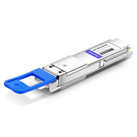
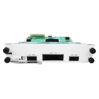
The optical module using a 100G (2X50G PAM4) solution includes 100G QSFP28 DWDM (C-band, 50Ghz wavelength interval). It is usually called 100G PAM4 QSFP28 in the industry, and its optical port carries 100GE service by 2 different 50G DWDM wavelengths. The electrical-port side adopts 4X25G NRZ, while the optical-port side has two solutions: CS and LC interfaces. The CS interface adopts 4 optical fibers, 2 in and 2 out. The duplex LC interface scheme adopts WDM technology, and 2 optical fibers can make for transmission. With the support of DCM dispersion compensation and EDFA, it can meet the requirements of at least 80km transmission distance, and the total bandwidth of a single fiber supports 96 waves x50G=4800G.

Figure 2: Schematic diagram of 100G QSFP28 DWDM optical module (CS interface)

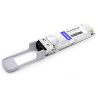
Figure 3: Schematic diagram of 100G QSFP28 DWDM optical module (LC interface)
100G(1x100G PAM4)Solution
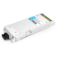
Optical modules using 100G (1x100G) solutions include 100G QSFP28 DWDM (C-band, 100GHZ). This product is mainly realized by DWDM light source + silicon light modulation technology. With the support of DCM+EDFA, it can meet 80km transmission, and the total bandwidth of a single fiber supports 48 waves x100G=4800G.

Figure 4: Schematic diagram of 100G QSFP28 DWDM optical module
With its advantages, PAM4 DWDM optical modules are usually used in 100G and 400G construction, such as point-to-point DCI, DWDM-based 100G Ethernet metro access, campus and enterprise links, 5G mobile access architecture, etc. For data center DCI 80km~120km, 50G/100G DWDM technology based on high-order PAM4 modulation can compete with coherent 200G/100G DWDM technology for market share at a low cost. As shown in the table below:
| Items | Dual-wave 50G PAM4 DWDM solution | Single-wave 100G PAM4 Solution | Coherent DP-QPSK Solution | |||||
|---|---|---|---|---|---|---|---|---|
| Power consumption | About 5.5W | About 5.5W | Above 20W | |||||
| Form factor | QSFP28 | QSFP28 | CFP2/CFP | |||||
| DWDM frequency space | 50GHz | 100GHz | 50GHz | |||||
| Is EDFA required? | YES | YES | YES | |||||
| DCM dispersion compensation | YES | YES | NO | |||||
| RX OSNR Tolerance | Very low, up to 2 EDFAs in cascade | Very low, up to 2 EDFAs in cascade | High, N EDFAs can be cascaded | |||||
| Typical total bandwidth | 96X50G | 48X100G | 96X100G | |||||
| Whether single-fiber/dual-fiber transmission can be achieved | easy | easy | Very difficult and requires two different ITLA light sources. | |||||
| Transmission distance | 80km~120km | 80km~100km | Far more than 80km |
Table 1: 50G PAM4 DWDM system VS 100G PAM4 DWDM system VS 100G DWDM coherent system
100G DWDM DCO QSFP28 Solution
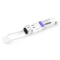
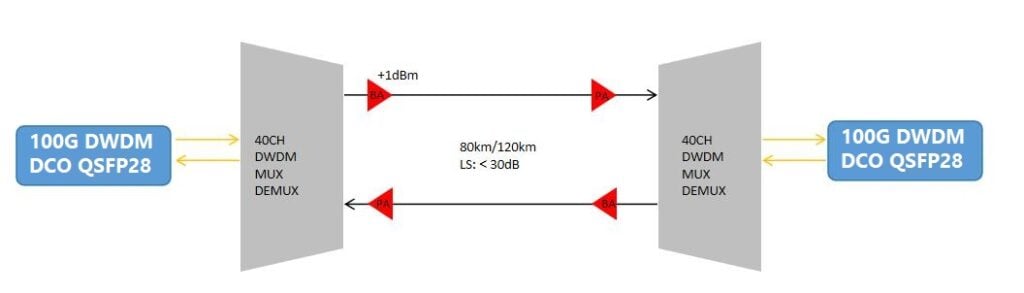
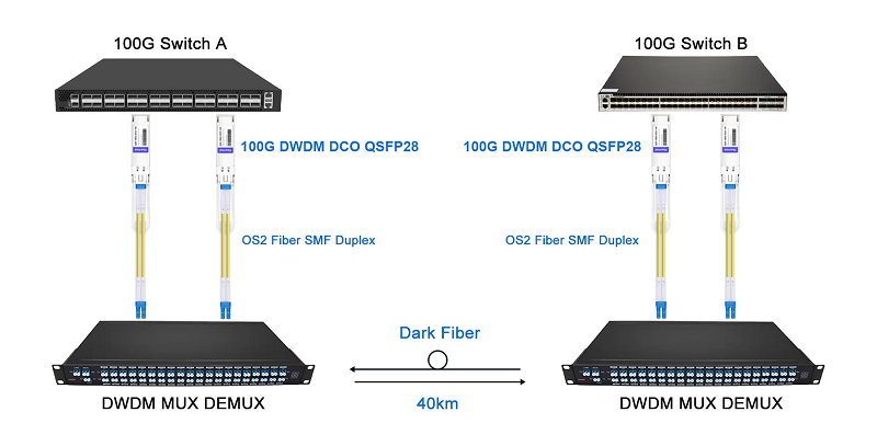
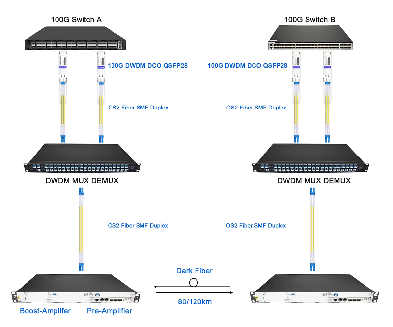
The 100G DWDM DCO QSFP28 optical module complies with the SFF-8636 (QSFP28 MSA) standard, ensuring compatibility with switches that support QSFP28 ports. It integrates Digital Coherent Optics (DCO) with a built-in Digital Signal Processor (DSP), enabling coherent modulation formats such as QPSK, making it suitable for long-distance DWDM transmission. For distances within 40 km, no EDFA (Erbium-Doped Fiber Amplifier) is required—only passive DWDM components like Mux/Demux are needed. For 80 km and 120 km links, EDFAs are necessary: a Boost Amplifier at the transmitter and a Pre-Amplifier at the receiver to compensate for signal attenuation. The DSP also handles chromatic dispersion compensation internally, eliminating the need for external DCM (Dispersion Compensation Module) or TDCM (Tunable DCM).
The module is compatible with mainstream 100G Ethernet switches such as Cisco Nexus, Arista 7050X, Juniper QFX, and Edgecore, without vendor lock-in, as long as the switch supports the SFF-8636 standard. It supports standard DWDM ITU grids (e.g., C-band, 50GHz or 100GHz spacing), making it suitable for point-to-point or multi-span DWDM networks. Typical applications include data center interconnect (DCI), metropolitan area networks (MAN), and long-haul transmission. In AI/HPC clusters, it supports high-bandwidth, low-latency connections.
Comparison with 100G (2x50G PAM4) DWDM QSFP28 and 100G Single Wave PAM4 DWDM QSFP28
| Feature | 100G DWDM DCO QSFP28 | 100G (2x50G PAM4) DWDM QSFP28 | 100G Single Wave PAM4 DWDM QSFP28 |
| Modulation | Coherent (e.g., DP-QPSK) | 2x50G PAM4 (non-coherent) | Single-wavelength PAM4 (non-coherent) |
| Wavelength/Channel | Single wavelength (DWDM ITU grid) | Dual wavelength (2x50G) | Single wavelength (100Gbps) |
| Dispersion Compensation | DSP-integrated, no DCM/TDCM needed | Requires external DCM/TDCM | Requires external DCM/TDCM |
| Transmission Distance (no EDFA) | ≤40km (passive DWDM) | ≤40km (module-dependent) | ≤40km (module-dependent) |
| EDFA Requirement | 80km/120km needs Boost + Pre-Amplifier | May require EDFA >40km | May require EDFA >40km |
| Power Consumption | Higher (~4.5–5W due to DSP) | Lower (~3.5–4W) | Lowest (~3–3.5W) |
| Complexity/Cost | High (DSP integration) | Medium (requires DCM/TDCM) | Lower (simpler design) |
| Typical Use Case | Long-haul DCI, MAN | Medium-short DCI | Short DCI or high-density links |
Key Differences
The DCO QSFP28 module uses coherent modulation (e.g., DP-QPSK) and DSP-based signal processing, offering superior dispersion tolerance and long-distance performance, ideal for 80–120 km links. In contrast, the 2x50G PAM4 module uses dual-wavelength PAM4 modulation and requires external DCM/TDCM for dispersion compensation, making it suitable for medium-range applications. The Single Wave PAM4 module, with its simple design and lowest power consumption, is best for short-range or high-density deployments, though it has limited dispersion tolerance.
While all three modules can operate without EDFAs for distances up to 40 km using passive DWDM components, longer distances (80–120 km) require EDFAs. The DCO module explicitly needs both Boost and Pre-Amplifiers, while PAM4 modules may also require amplification depending on their optical budget and link loss.
In terms of power and cost, the DCO module consumes more power (~4.5–5W) due to its DSP but offers better performance. PAM4 modules are more power-efficient (3–4W) and cost-effective but may incur additional system costs due to the need for DCM/TDCM.
Usage on 100G Ethernet Switches
The 100G DWDM DCO QSFP28 module is compatible with switches that support QSFP28 ports and the SFF-8636 standard, such as Cisco Nexus 9300, Arista 7050X, Juniper QFX5200, and Edgecore AS7712-32X. Compatibility depends on firmware support and port configuration. For example, Cisco Nexus 9300 requires NX-OS version 7.x or later to support DWDM DCO modules. Cisco typically does not require additional licenses for basic use, but advanced features like IPoDWDM or TXP/MXP may require Advantage or Premier licenses. Arista and Juniper generally do not require special licenses but may need confirmation of DCO support in their NOS (e.g., SONiC).
For ≤40 km links, passive DWDM Mux/Demux (e.g., 8/16/40 channels) can be used without EDFAs. For 80 km or 120 km, a Boost Amplifier at the transmitter and a Pre-Amplifier at the receiver are needed to maintain signal integrity.
Practical Deployment Recommendations
The DCO QSFP28 module is ideal for long-distance transmission (40–120 km), such as DCI or MAN scenarios, where simplified system design and high reliability are desired. Its DSP provides excellent dispersion and noise tolerance. In contrast, 2x50G and Single Wave PAM4 modules are better suited for short-distance (≤40 km) or cost-sensitive deployments. These modules are appropriate for networks with existing DWDM infrastructure and can tolerate the additional complexity of DCM/TDCM. Single-Wave PAM4 is especially suitable for high-density, short-reach connections within data centers.
In AI/HPC environments, DCO QSFP28 modules are used for low-latency, high-bandwidth interconnects between data centers, often in conjunction with DPUs like NVIDIA BlueField to enhance network performance. PAM4 modules are more appropriate for cost-effective spine-leaf architectures within data centers.
The 100G DWDM DCO QSFP28 module adheres to the SFF-8636 standard, is compatible with mainstream 100G switches, and features integrated DSP for dispersion compensation. It requires no EDFA for ≤40 km and uses Boost + Pre-Amplifier for 80–120 km, making it ideal for long-haul DCI. PAM4-based modules, while lower in cost and power consumption, require external DCM/TDCM and are better suited for short-distance or high-density applications. Compatibility with switches like Cisco, Arista, and Juniper is generally strong, though firmware and licensing requirements should be verified.
Critical Technologies of 100G Coherent DP-QPSK Scheme
Polarization Multiplexing Quadrature Phase Shift Keying (PM-QPSK)
QPSK is a multivariate (quaternary) digital frequency band modulation method. The sinusoidal carrier of its signal has 4 possible discrete phase states, and each carrier phase carries 2 binary symbols. PM-QPSK divides a single 100G signal into two 50G carrier signals with different polarization states and performs QPSK modulation on each carrier. Therefore, this method can reduce the channel baud rate to half. At the same time, since each polarization state can use 4 phases to represent bit information, it is possible to reduce the channel baud rate to half. Consequently, after PM-QPSK encoding, the baud rate can be reduced to a quarter of the bit rate.
The following is a schematic diagram of the PM-QPSK encoding method:

Figure 5: Schematic diagram of PM-QPSK coding
SD-FEC
FEC technology is widely used in optical communication systems. Different FECs can obtain different system performances. According to the different processing methods of received signals, FEC can be divided into hard and soft-decision codes.
The hard-decision code is a decoding method based on the traditional error-correcting code viewpoint. The demodulator first makes the best hard decision on the channel output value. The FEC redundancy of the hard decision is about 7%, which has been widely used in the field of optical communication.
Soft-decision decoding makes full use of the waveform information output by the channel. The demodulator sends a real value output from the matched filter to the decoder, that is, the soft-decision decoder needs not only “0/1” code streams but also “soft information” to describe the reliability of these code streams. The farther away from the decision threshold, the higher the reliability of the decision, otherwise the lower the reliability.
To reflect the degree of distance, it is necessary to divide the judgment space more finely. In addition to dividing the “0/1” threshold, the “0” and “1” spaces are also divided by the “confidence threshold” to illustrate the relative position of the decision point in the decision space. Compared with hard decision, soft decision contains more channel information. The decoder can make full use of this information through probabilistic decoding, to obtain greater coding gain than hard-decision decoding.
OIF recommends that 100G choose soft-decision forward error correction coding (SD-FEC) with redundancy of less than 20%. In this case, the net coding gain can reach about 10.5dB. Using SD-FEC 100G technology can reach the same level of transmission distance as 10G.
Coherent technology
Coherence refers to a demodulation mechanism in which the waves have the same amount of vibration, the same vibration direction and frequency, and a fixed phase relationship. It is a detection method in which the carrier of the modulated signal is multiplied by the received modulated signal, and then the modulated signal is obtained by low-pass filtering.
Coherent detection detects intensity, phase, and frequency-modulated optical wireless signals. The optical signal is mixed with the local oscillator laser (LO) at the receiving end before entering the optical receiver, resulting in an intermediate frequency component equal to the difference between the frequency of the LO laser and the frequency of the original light source.
Compared with direct detection, coherent detection is prone to obtaining a large signal-to-noise ratio. It has more recoverable signal types, and better frequency selectivity, which is more suitable for DWDM systems. The digital coherent receiver maps all optical properties of the optical signal to the electrical domain through phase diversity and polarization diversity. It also uses mature DSP technology to achieve polarization demultiplexing and channel linearity damage compensation in the electrical domain. All these simplify the optical dispersion compensation and polarization demultiplexing design in the transmission channel to reduce and eliminate the dependence on optical dispersion compensators and low PMD fibers.
However, the digital coherent receiver transfers the complexity of the transmission channel design to the receiver. The cost of obtaining better detection properties in coherent detection is that the complexity of the system is greatly increased, and it lacks flexibility.
Enhancing DWDM Networks with 100G Coherent Modules
The adoption of 100G coherent modules has revolutionized Dense Wavelength Division Multiplexing (DWDM) systems, enabling high-capacity, long-distance optical transmission to meet the demands of modern networks. These modules utilize advanced modulation techniques, such as Polarization-Multiplexed Quadrature Phase-Shift Keying (PM-QPSK), combined with coherent detection and digital signal processing (DSP) to deliver robust performance. By compensating for impairments like chromatic dispersion and polarization mode dispersion (PMD) in the electrical domain, 100G coherent modules ensure signal integrity over distances exceeding 1000 km, making them ideal for data center interconnects (DCI), metropolitan networks, and long-haul applications. Their high spectral efficiency and compatibility with existing DWDM infrastructure make them a cornerstone for operators seeking to scale bandwidth efficiently.
100G coherent modules, typically housed in compact form factors like CFP or CFP2, offer remarkable flexibility for network upgrades. Equipped with tunable lasers aligned to the ITU DWDM grid (50GHz or 100GHz spacing), these modules enable dynamic wavelength allocation, simplifying network management and reducing spare inventory costs. For example, FiberMall’s 100G coherent CFP2-DCO modules support up to 120 channels in the C-band, providing a seamless upgrade path from 10G or 40G systems without requiring extensive infrastructure changes. When paired with Erbium-Doped Fiber Amplifiers (EDFAs) and dispersion compensation modules (DCMs), these modules deliver reliable performance for both metro and long-haul networks, catering to the growing needs of cloud computing, 5G backhaul, and enterprise connectivity.
Implementation Schemes for 100G Coherent Modules in DWDM Systems
To fully leverage 100G coherent modules, network operators can implement tailored schemes to address specific use cases and optimize performance.
Scheme 1: Metro DCI Deployment focuses on deploying 100G coherent modules in data center interconnects within metropolitan areas. By integrating these modules with Reconfigurable Optical Add-Drop Multiplexers (ROADMs), operators can achieve flexible wavelength routing for high-speed, low-latency links over 80–120 km. This scheme supports up to 9.6 Tbps per fiber pair (96 channels at 100G), making it ideal for hyperscale data centers with heavy traffic demands.
Scheme 2: Long-Haul Transmission with Coherent Detection utilizes 100G coherent modules alongside advanced Forward Error Correction (FEC) and EDFAs to extend transmission distances beyond 1500 km. This approach is well-suited for intercity networks, where signal quality is maintained through DSP-based compensation, reducing the need for costly regenerators.
Scheme 3: Hybrid 10G/100G Network Upgrades enables operators to integrate 100G coherent modules into existing 10G DWDM systems, offering a cost-effective path to higher capacity. By using flexible grid ROADMs, operators can allocate 50GHz channels for 100G modules while retaining 10G channels on the same fiber, achieving a total capacity of up to 8 Tbps (80 channels of 100G). This scheme is particularly effective for operators looking to incrementally scale their networks without overhauling legacy infrastructure.
Scheme 4: 5G Backhaul Optimization leverages 100G coherent modules to support the high-bandwidth, low-latency requirements of 5G networks. By deploying these modules in metro rings with tunable wavelengths, operators can dynamically adjust capacity to meet fluctuating traffic patterns, ensuring reliable connectivity for mobile edge computing and enterprise applications.
The versatility of 100G coherent modules positions them as a critical component for building scalable, future-ready DWDM networks. Their integration of advanced DSP and energy-efficient components, such as those found in FiberMall’s 100G coherent modules, ensures high performance while aligning with sustainability goals. By adopting these implementation schemes, operators can address diverse network requirements, from high-density DCI to long-haul connectivity, while preparing for future upgrades to 200G or 400G systems. As bandwidth demands continue to grow, 100G coherent modules provide a reliable, cost-effective solution for delivering high-capacity optical networks.
Basic principles of 100G implementation
The basic principle of 100G line-side transmitter
The design goal of the 100Gb/s line-side optical module is to apply to long-distance optical transmission and support the line-side transmission of DWDM equipment of OTU4. The following figure shows the block diagram of the transmitting end of the 100Gb/s line-side optical module.
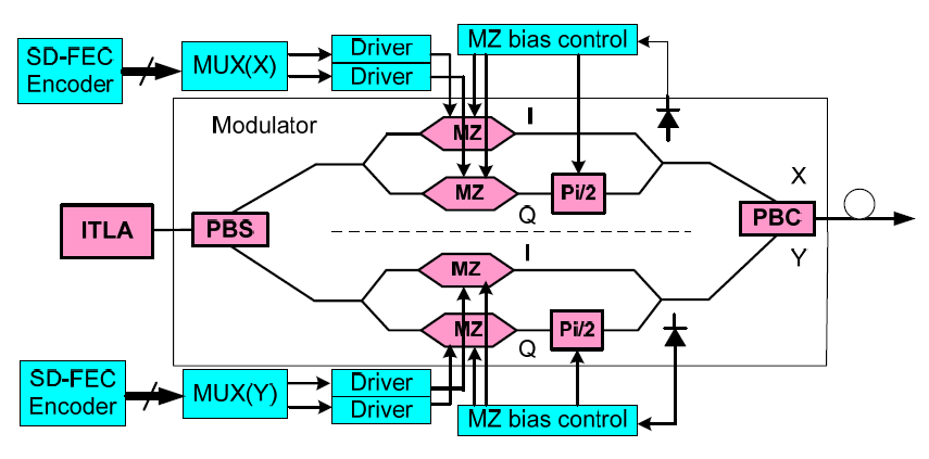
Figure 6: Schematic diagram of 100Gb/s line test optical module transmitter
As shown in the figure, the continuous light output by the integrated tunable laser (ITLA) is sent to the QPSK modulator, which becomes two light waves after the PBS is generated by a polarization separation device in the modulator. Each polarized light is modulated by a QPSK modulator, and there are I and O signals generated by the MUX when modulating the signal. The broadband amplifier and driver amplify the I and O signals and apply them to the modulator to generate electro-optical modulation.
The modulated two QPSK signals are synthesized by a PBC and a PM-QPSK polarization multiplexed signal is output. For the QPSK modulator (Modulator), it is also necessary to carry out feedback control (MZ bias control) for the multiple bias points of the I, Q, and Pi/2 phase through closed-loop control, so that the QPSK modulator can work stably for a long time under normal bias state. In addition, the transmitting unit also encodes the service data to be transmitted through the SD-FEC encoder and inputs it into MUX(X) and MUX(Y). It generates 4-channel serial data using parallel-to-serial conversion and outputs it to the driver.
The basic principle of the receiving side
As shown in the figure below, the PM-QPSK optical signal is received by the coherent receiving unit of the optical module after long-distance transmission. The optical signal is divided into two mutually-orthogonal polarized optical signals by the polarization beam splitter, denoted as the X direction and the Y direction. The optical signals in the two directions are coherently mixed at 90 degrees (900Hybrid)with the corresponding local oscillator polarized light. The signal output by the mixing frequency undergoes photoelectric conversion through a balanced photoelectric detector and then is sampled and quantized by the ADC to complete the analog/digital conversion. Finally, the discrete digital sequence after sampling and quantization is sent to the DSP unit for processing.
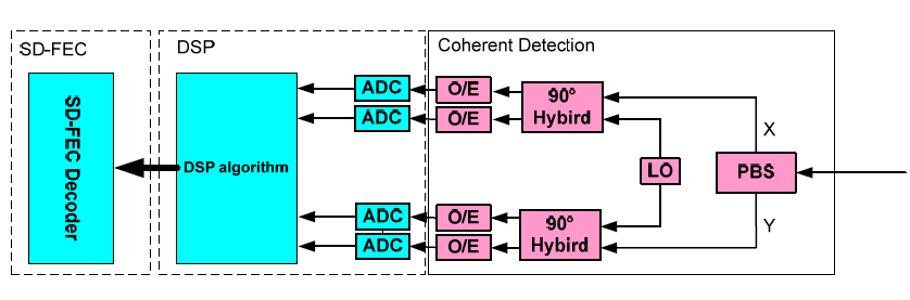
Figure 7: block diagram of 100Gb/s line-side optical transceiver receiver
In the DSP, the digital signal is synchronized by clock recovery processing. The polarization demultiplexing and the removal of CD, PMD, and partial nonlinear effect impairment are realized by electric domain equalization. The frequency difference between the local oscillation light source and the transmitting optical carrier, as well as the effect of phase noise, is eliminated by frequency offset estimation and corresponding judgment processing. The processed data is then sent to the SD-FEC decoder unit for decoding, and finally, the data signal is recovered.
The basic principle of the DSP algorithm
The DSP unit completes the DSP algorithm, which is mainly divided into five sub-functions: Clock Recovery, Equalization with Polarization Demultiplexing, Carrier Estimation, Phase Estimation, Slicer & Decoder. Its functional block diagram is shown in the following figure.

Figure 8: Block diagram of the digital signal processing unit
The following will introduce each unit in the block diagram:
- Digital clock recovery
The purpose of digital clock recovery is that, since the sampling clock of the ADC is independent of the symbol clock of the transmitting end, the symbol sampling time of the interpolation filter receivers must be used. This enables the adjusted sampling clock of the receiver to synchronize with the transmitting symbol clock, that is, to ensure the sampling rate of the ADC exactly matches the symbol rate.
- Equalization and polarization demultiplexing
Equalization and polarization demultiplexing are performed on a single polarization. The function of equalization is to eliminate the signal crosstalk caused by the linear factor of the channel. It can be realized by FIR with fixed or variable tap coefficients, while polarization demultiplexing needs to be realized by a butterfly filter. Polarization demultiplexing is to separate two polarized signals. That is because when the signal is transmitted, there is a crosstalk between the two polarizations (caused by polarization coupling). And due to the polarization rotation, the signal polarization after the PBS at the receiving end does not correspond to the initial polarization.
- Carrier frequency offset estimation
Due to the non-ideal characteristics of the laser, the oscillation frequency of the local oscillator laser in the optical coherent receiver may have a deviation from the carrier frequency. This frequency offset is reflected in the symbol, which is the phase offset. For a phase modulation system such as PM-QPSK, the phase offset caused by the frequency offset must be removed before it is possible to demodulate the final data symbol. Therefore, frequency offset estimation is an indispensable module for receivers. The principle is to detect the size of the frequency offset, and then perform phase correction on the symbol to remove the influence of the frequency offset, according to the estimated frequency offset value.
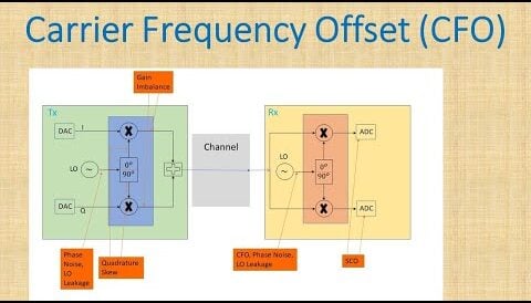
Figure9:carrier frequency offset estimation
- Carrier phase offset estimation
Due to the linewidth of the laser, some phase shift occurs near its true oscillation frequency. In consideration of the error of the frequency offset estimation, the phase offset of the symbol after the frequency offset estimation still exists. This offset changes with time, which can cover all ranges from 0 to 2π. The purpose of carrier phase recovery is to remove this part of the phase offset so that the output symbol phase can be directly used for symbol decision. The basic principle of carrier phase estimation is that the unexpected phase offset of the information phase is obtained and removed from each symbol.
- Decoding and data recovery
For QPSK, after the phase of the signal is recovered, two polarized I and Q signals can be obtained according to the phase modulation rule. For DQPSK, after the phase of the signal is recovered, the phases of the two symbols need to be subtracted to obtain two polarized I and Q signals.
Technical Features and Advantages of the 100G System
As we all know, every increase in single-channel rate will be limited by transmission impairments including OSNR tolerance, chromatic dispersion, PMD, and nonlinearity. Therefore, more advanced technologies are required to reduce the impact of these transmission impairments. 100G integrates multiple technologies such as polarization multiplexing, phase modulation, super FEC, coherent detection, and DSP. The characteristics of the current 100G technology solutions are as follows:
- By using the technology of polarization multiplexing and the mutual orthogonality between the two polarization states of the optical signal, two channels of information are carried on the same optical carrier.in doing so, the signal symbol rate is reduced by half. The combination of coherent detection with ADC and DSP is also a key technological breakthrough in 100G. Compared with direct detection and self-coherent demodulation, the combination of coherent detection and DSP technology can effectively improve demodulation efficiency and receiver sensitivity.
- QPSK technology can double the amount of information carried by the optical carrier, and its combination with polarization multiplexing reduces the baud rate of the 100G signal to about 25Gbaud/s. Therefore, QPSK can be applied in the OTN system with a 50GHz interval and can reduce signal requirements for fiber nonlinearity tolerance.
- The 100G technology can effectively improve the coding gain through the LDPC (Low-Density Parity-Check Code) solution and the soft decision method.
- The combination of coherent detection with ADC and DSP is also a key technological breakthrough in 100G. Compared with direct detection and self-coherent demodulation, the combination of coherent detection and DSP technology can effectively improve demodulation efficiency and receiver sensitivity.
Conclusion
For data center interconnection (DCI) within 100km transmission distance, FiberMall provides solutions of 100G (2X50G PAM4) DWDM QSFP28 and 100G (1x100G PAM4) DWDM QSFP28. For metropolitan area networks, the transmission distance is more than 100km, FiberMall provides two long-distance solutions, 1x 100G QSFP28 to 1x 100G CFP-CDO and 2x 100G QSFP28 to 1x 200G CFP2 DP-8QAM or DP-16QAM. Through the joint efforts of all employees of FiberMall, 100G DWDM technology has become very mature and has been widely deployed in data centers and metropolitan area networks around the world.
Related Products:
-
 Cisco Compatible 100G DWDM QSFP28 C41 C42 100GHz CS DDM Optical Transceiver
$1600.00
Cisco Compatible 100G DWDM QSFP28 C41 C42 100GHz CS DDM Optical Transceiver
$1600.00
-
Q28-DW100G23-80C Compatible 100G DWDM QSFP28 PAM4 Single Wave C23 1558.98nm 100GHz LC 80km DDM Optical Transceiver Module
$1900.00
-
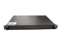
EDFA 40/80 Channels DWDM C-Band Optical Pre-Amplifier Maximal Output Power +16dBm Gain 25dB Saturated Optical Power -9dBm
$1139.00
-
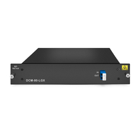
DCM 80km DCF-based Passive Dispersion Compensation Module, 8.0dB Low Loss, LC/UPC Connector
$929.00
-
200G Transponder/Muxponder : 2x 100G QSFP28 to 1x 200G CFP2 DP-8QAM or DP-16QAM
$4550.00
-
CFP2-200G-DCO 200G Coherent CFP2-DCO C-band Tunable Optical Transceiver Module
$6500.00
-
Q28-100G-DCO-22C Compatible 100G DWDM DCO QSFP28 C-band C22 1559.79nm 100GHz Duplex LC Optics Transceiver
$3600.00
-
Q28-100G-DCO-28C Compatible 100G DWDM DCO QSFP28 C-band C28 1554.94nm 100GHz Duplex LC Optics Transceiver
$3600.00
-
Q28-100G-DCO-21C Compatible 100G DWDM DCO QSFP28 C-band C21 1560.61nm 100GHz Duplex LC Optics Transceiver
$3600.00
-
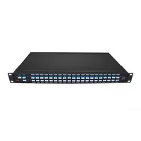
Low IL 3.5dB DWDM MUX DEMUX 40CH (C21-C60) LC/UPC Dual Fiber 1U Rack
$1200.00
-
EDFA 40/80 Channels C-Band Optical Amplifier Maximal Output Power +16dBm Gain 25dB Saturated Optical Power -9dBm
$1200.00
-
EDFA 40/80 Channels C-Band Optical Amplifier Maximal Output Power +16dBm Gain 25dB Saturated Optical Power -9dBm Built in VOA Adjustable Range 1~20dB
$1796.00