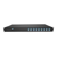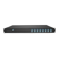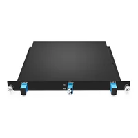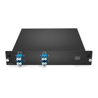

A CWDM OADM adds and drops selected wavelengths at an intermediate site while all other channels continue along the express path without being dropped or converted. Use one when one or more channels need to leave or join a fiber mid-span. Use a mux/demux at terminal sites, where all channels are combined or separated for local equipment.
Priya found out why that distinction matters on a Tuesday in March. She had designed a six-node, 42 km metro ring for a regional utility, and the first five nodes passed acceptance. Node six came up at -17.8 dBm against a receiver sensitivity of -18 dBm, leaving almost no operating margin.
The fiber was fine. The transceivers were fine. Node six was simply the sixth OADM site in the chain. The channel had already accumulated five upstream express-path losses before reaching the final site’s add/drop filter. Node count, not just distance, can determine whether a passive ring closes within its optical budget.
This guide gives you the numbers and design considerations needed to size a ring before ordering hardware.
Key Takeaways
- A CWDM OADM is a mid-span device. A mux/demux is a terminal device, and confusing the two is a common specification error.
- Every OADM a channel passes through adds express-path loss, typically 0.8 to 3.2 dB depending on channel count and filter configuration.
- Single-fiber OADMs use two wavelengths per bidirectional link and require a matched pair with transmit and receive wavelengths swapped at each end.
- “East and west” describes which fiber direction a module serves, not a transmission speed or protocol.
- A CWDM OADM module typically costs $70 to $250, depending on its channel count and configuration. The engineering effort belongs in the channel plan, not just the purchase order.
What Is a CWDM OADM?
An optical add-drop multiplexer is a passive filter module that removes one or more selected CWDM channels from a fiber at an intermediate site, sends them to local equipment, and inserts replacement signals on the same wavelengths. All other channels continue along the express path without electrical conversion.
A CWDM OADM module has four main port types. Line ports connect the trunk fiber. The express path carries channels that are not dropped. Drop ports deliver selected wavelengths to local receivers, while add ports accept signals from local transmitters and insert them back onto the trunk.
Nothing in that optical path requires power, software, or cooling. A CWDM OADM is protocol-transparent to Ethernet, Fibre Channel, SDH, and video signals, provided their wavelengths and optical characteristics fall within the module’s specifications.
Most units use thin-film filters. Depending on the filter design, selected wavelengths are routed to add/drop ports while other wavelengths continue along the express path. Each module is configured for specific wavelengths, so changing the channel plan may require replacing the module.
That’s useful in outside plant, where a cabinet with no power, fan, or management card has fewer components that can fail. The trade-off is visibility. A passive OADM cannot report optical loss or a missing channel, so problems are usually identified through measurements at the local or remote equipment.
OADM vs Mux/Demux: Different Job, Different Site
| Question | CWDM OADM | CWDM mux/demux |
| Where it sits | Intermediate site on a linear or ring span | Terminal or headend |
| Channels handled | 1 to 4, dropped and added locally | All channels in the plan |
| Traffic through it | Most channels pass untouched | Every channel terminates |
| Typical loss | 0.8 to 2.0 dB express per pass | 1.5 dB for 4 channels, about 5 dB for 18 |
| Best fit | Adding a site to existing fiber | Ending a span at a switch or router |
These are representative values. Actual insertion loss depends on the product design and vendor specifications.
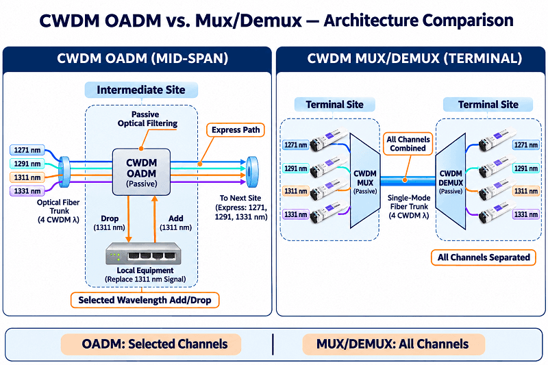
A common mistake is buying a full mux/demux for a one-channel mid-span site. A 4-channel mux/demux combines or separates four wavelengths at a terminal location, with each channel requiring its own compatible transceiver. A 1-channel OADM can drop one selected wavelength while allowing the remaining channels to continue along the express path.
If you know which channels leave at which site, send the plan to our engineers for a loss check before ordering. Request a channel-plan review.
The Specs That Decide Your Design
Insertion loss is the number that matters, and datasheets sometimes report it in ways that make comparisons difficult. Your design needs two separate figures: the loss a channel experiences when it is dropped or added locally, and the loss it experiences when passing through the express path.
| Channels | Express loss per pass | Add/drop loss | Typical fit |
| 1 | 0.8 to 1.2 dB | 1.0 to 1.5 dB | One service at a linear site |
| 2 | 1.0 to 1.5 dB | 1.0 to 1.5 dB | Two services, or one protected pair |
| 4 | 1.5 to 2.0 dB | 1.2 to 1.8 dB | Small ring node |
| 8 | 2.5 to 3.2 dB | 2.5 to 3.2 dB | Dense node, rarely worth it mid-span |
Note: These are industry-typical reference ranges, not guaranteed specifications. FiberMall’s 1-channel single-fiber OADM is specified with an insertion loss of ≤0.6 dB, while its 4-channel dual-fiber unit is specified at ≤1.4 dB. These are published insertion-loss figures; do not automatically interpret them as separate express-path and add/drop loss values. Check the model-specific datasheet or ask the supplier to confirm both values separately.
The other specifications define the operating envelope. Depending on the product, typical design targets may include adjacent-channel isolation ≥30 dB, non-adjacent-channel isolation ≥40 dB, return loss ≥45 dB, directivity ≥50 dB, and PDL ≤0.2 dB. Maximum optical input power is commonly specified in the 300 to 500 mW range, but this must be confirmed for the selected module.
Check the operating temperature against the enclosure environment. Commercial components are often rated from -20 °C to +70 °C, with industrial options available from -40 °C to +85 °C. A sealed outdoor cabinet exposed to direct sunlight can exceed the temperature range of commercial-grade components.
Single-Fiber vs Dual-Fiber CWDM OADM
A dual-fiber OADM uses one fiber strand per direction. The same wavelength can travel in both directions because the two directions use separate fibers. Troubleshooting is generally simpler, and many metro ring designs use this arrangement when fiber pairs are available.
A single-fiber OADM carries both directions on one strand. Each bidirectional link needs two wavelengths, and the two ends must be a matched pair with transmit and receive wavelengths swapped.
| Link | Site A transmits | Site A receives | Site B transmits | Site B receives |
| 1 | 1271 nm | 1291 nm | 1291 nm | 1271 nm |
| 2 | 1311 nm | 1331 nm | 1331 nm | 1311 nm |
Eighteen available CWDM channels can theoretically support nine bidirectional wavelength pairs on one strand, provided the OADM configuration and channel plan support all required wavelengths.
Optical reflections also require careful attention in single-fiber bidirectional systems because back-reflections can introduce interference and background noise at the receiver. Use APC connectors where supported, or clean, compatible UPC connectors with appropriate return-loss performance. Never directly mate APC and UPC connectors, and always cap unused ports.
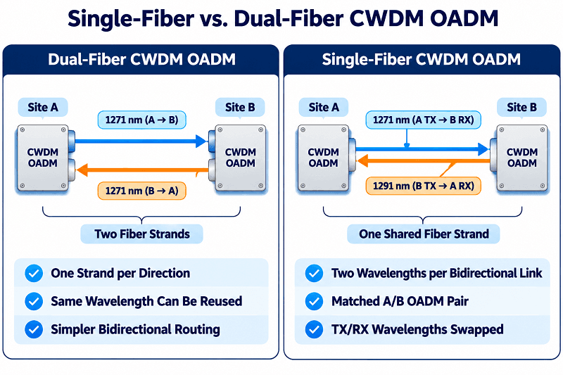
Tomas learned that at a hospital campus. He ordered two identical 1-channel single-fiber OADMs and got a dark link: both transmitted on 1471 nm and both received on 1491 nm. The vendor supplied the matched B-version module, and the link came up two days later.
Nothing was broken. The two modules simply weren’t a matched pair.
East and West: What the Configuration Actually Means
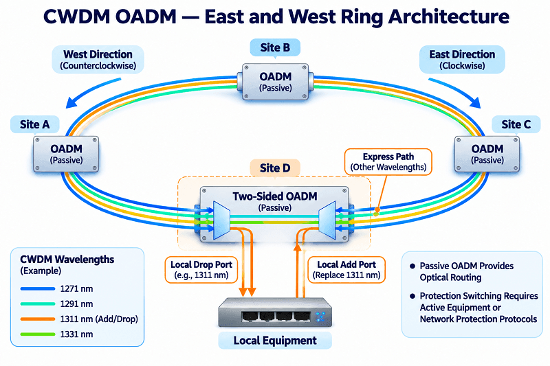
On a ring, traffic can arrive at a node from two directions. Vendors commonly label those directions east and west, and an OADM can serve one or both.
A one-sided module has line ports designed for a single direction. It suits a linear bus or a node that only needs to drop traffic from one side. A two-sided module supports add/drop access toward both directions, allowing the node to connect with both neighboring sites.
This arrangement provides the optical paths needed to design ring protection. A wavelength can be provisioned over alternative paths around the ring, or a protected service can be carried in both directions using a suitable network architecture. However, a passive OADM does not perform protection switching or traffic rerouting. These functions must be implemented by active network equipment or protection protocols such as 1+1 protection.
Confirm the naming before ordering. Codes such as SS, SD, DS, and DD appear on some product pages, but they are not universal industry standards. Describe the required traffic path and ask the vendor to confirm the module configuration.
Loss Budget: Why Node Count Limits a Passive Ring
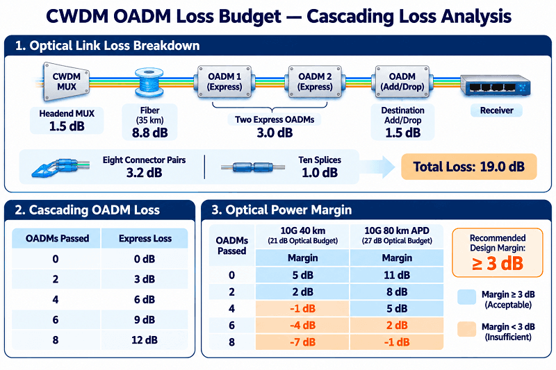
Here is an illustrative 10G loss budget for a hub plus three OADM sites on a 35 km span. The channel destined for the last site passes through two upstream OADMs before being dropped at the destination.
| Item | Loss |
| Headend mux, 4 channels | 1.5 dB |
| Fiber, 35 km at 0.25 dB/km | 8.8 dB |
| Express through two OADMs at 1.5 dB | 3.0 dB |
| Drop at the last site | 1.5 dB |
| Eight connector pairs at 0.4 dB | 3.2 dB |
| Ten splices at 0.1 dB | 1.0 dB |
| Total | 19.0 dB |
A 10G module rated for 40 km, with a +3 dBm transmitter output and -18 dBm receiver sensitivity, provides a nominal 21 dB optical budget. The span therefore leaves 2 dB of margin. An 80 km APD module with the same assumed transmitter output and -24 dBm receiver sensitivity provides a 27 dB budget, leaving 8 dB of margin.
These are illustrative calculations. Actual transmitter output, receiver sensitivity, dispersion tolerance, and optical reach must be verified against the selected transceiver’s datasheet. Use guaranteed minimum transmitter output and specified receiver sensitivity for conservative engineering calculations.
The table below keeps the other 16.0 dB of fixed loss unchanged, including the headend mux, fiber, destination add/drop loss, connectors, and splices. It varies only the number of OADMs the channel passes through.
| OADMs passed | Express loss | Margin, 10G 40 km | Margin, 10G 80 km APD |
| 0 | 0 dB | 6.5 dB | 12.5 dB |
| 2 | 3.0 dB | 3.5 dB | 9.5 dB |
| 4 | 6.0 dB | 0.5 dB | 6.5 dB |
| 6 | 9.0 dB | -2.5 dB | 3.5 dB |
| 8 | 12.0 dB | -5.5 dB | 0.5 dB |
Under these assumptions, the 40 km link falls below the recommended 3 dB design margin after two express-path passes and exceeds its 21 dB optical budget at four passes. The 80 km APD link falls below the 3 dB margin after six passes and exceeds its budget at eight passes.
Rule: Budget the worst-case path, then keep at least 3 dB of margin. A ring designed with zero margin can fail after a repair splice, connector replacement, or other change in the optical path.
Channel Planning Across a Ring or Linear Bus
Plan wavelengths on the ITU-T G.694.2 CWDM grid before ordering modules: channel plan first, optics second, and hardware last. Reversing this sequence can increase cost and complicate deployment.
Give the farthest sites channels with the lowest verified path loss, based on the channel-specific specifications of the selected OADMs. A channel dropped at node six has already passed through five upstream express paths, in addition to the add/drop loss at the destination node. Assign sufficient optical budget to the longest paths rather than relying on the same transceiver configuration for every site. Pair long paths with optics that provide adequate reach and keep shorter paths on standard parts where appropriate.
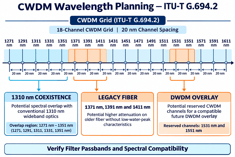
Leave the 1531 nm and 1551 nm CWDM channels free if a future DWDM overlay is planned. These wavelength windows can support additional DWDM channels through compatible coexistence filters. However, the available DWDM passband, filter insertion loss, and amplifier placement must be evaluated during the initial channel plan. Simply leaving these CWDM channels unused does not guarantee future DWDM compatibility.
On legacy fiber, avoid channels that overlap with existing traffic. Conventional 1310 nm wideband optics may overlap with CWDM channels from 1271 to 1351 nm, depending on transmitter spectral characteristics and filter passbands. Similarly, 1550 nm optics operating in the 1530 to 1565 nm range may overlap with the 1531 nm and 1551 nm CWDM channels. Verify spectral compatibility before combining these signals on the same fiber.
Channels 1371, 1391, and 1411 nm can experience higher attenuation on older fiber that does not support low-water-peak transmission. Check the fiber specification before using these channels.
GPON also needs careful consideration. Standard GPON systems use approximately 1310 nm for upstream transmission and 1490 nm for downstream transmission, while 1550 nm is often used for RF video overlay. Avoid overlapping CWDM channels around these wavelengths unless the optical coexistence design has been verified.
Finally, the last site in a linear chain usually does not need an OADM because no channels need to continue beyond it. Use a terminal demux when multiple CWDM channels need to be separated, or a direct optical connection for a single-wavelength link.
When to Use an OADM, and When a Mux Wins
Use a CWDM OADM when all of the following are true:
- The site sits between two terminals, rather than at the end of the span.
- One to four channels need to leave or join locally, or the selected OADM supports the required channel count.
- The existing channel plan allows other wavelengths to continue along the express path.
- The loss budget closes with at least 3 dB of margin.
- The site has no power, or you want to avoid powered equipment there.
- The services can rely on protection provided by Layer 2/Layer 3 protocols or separate optical protection equipment where required.
Choose a mux/demux instead when the site is a terminal where all channels in the span need to be combined or separated. If four or more channels need to be added or dropped while other wavelengths continue through the site, compare a higher-channel-count OADM with a mux/demux based on the optical path, insertion loss, and overall cost. If a monitor port is required, specify it and confirm that the selected configuration supports it.
Choose something else when the requirement is per-channel remote reconfiguration. A fixed OADM cannot change its wavelength assignment remotely; a channel-plan change generally requires physical replacement or reconfiguration of the module. Most metro OADMs deployed today remain fixed because fixed filters are cheaper and simpler. When remote wavelength selection and reconfiguration are required, the appropriate solution is a ROADM architecture, not simply a larger fixed OADM.
CWDM OADM Cost: What Each Added Site Actually Costs
A CWDM OADM module typically costs $70 to $250, depending on its channel count, fiber configuration, and packaging. This covers the module itself, not the complete cost of an installed site, which may also require transceivers, connectors, patch panels, chassis, and installation labor.
| Item | FiberMall list price | Market reference |
| 1-channel single-fiber OADM, LGX | $70 | About €115 for a comparable module |
| 2-channel dual-fiber OADM, LGX | $130 | About $176 in an ABS housing |
| 4-channel dual-fiber OADM, LGX | $250 | About $388 in a 1U chassis |
| 2-slot LGX chassis | $38 | Varies by vendor |
Note: Prices are list prices published on the FiberMall CWDM OADM category page on November 10, 2026. Custom wavelengths, connector types, and packaging can change them.
Lena compared two options for four new PoPs on a metro ISP network. New fiber construction to the fourth building was quoted at $38,000 with a 14-week lead time. Four 4-channel OADMs and two chassis came to about $1,076 in hardware, and the sites were commissioned within a week using the existing fiber infrastructure.
The comparison is not always that wide. A CWDM OADM requires compatible colored optics at both ends, which cost more than standard grey 1310 nm parts, and the engineering work is real. In this illustrative comparison, the new-fiber construction quote was approximately 35 times the OADM hardware subtotal. These are not like-for-like project costs, since the OADM figure excludes transceivers, installation, and other supporting equipment.
Compare the 1-channel single-fiber module with the 4-channel dual-fiber module before you size the site.
Deploying and Commissioning a CWDM OADM
Commissioning is mostly about accurate documentation and verification, which is what makes a passive optical deployment reliable. Record the expected receive power for every channel before connecting patch cords.
- Confirm the channel plan and label both ends of every fiber with the wavelength and site identification.
- Inspect and clean every connector. A dirty LC connector can introduce more loss than the OADM itself.
- Measure receive power per channel and compare it with the calculated value.
- Record the baseline in the handover document, including the date and the optical power meter used.
- Maintain at least one compatible spare transceiver for each deployed wavelength and optical configuration.
| Symptom | Likely cause | First check |
| One site dark, others fine | Wrong OADM slot or unmatched pair | Read the wavelength label at both ends |
| Far site marginal, near sites fine | Express loss used up the budget | Count OADMs passed and measure Rx power |
| Link worked until a node was added | New express loss | Recompute the budget for the worst path |
| One channel dead, others live | Drop port or SFP mismatch | Swap the SFP, then the port |
| Intermittent errors on single fiber | Reflection or dirty connector | Inspect, clean, confirm APC |
| Errors on 1591 or 1611 nm at 10G | Dispersion | Shorten the span or move to a lower channel |
FAQ
What is a CWDM OADM?
A CWDM add-drop multiplexer, or CWDM OADM, is a passive module that drops selected wavelengths at an intermediate site and adds replacement signals on the same wavelengths. All other channels continue along the express path without electrical conversion.
What is the difference between an OADM and a mux/demux?
An OADM sits mid-span and adds or drops selected channels while allowing the remaining wavelengths to pass through. A mux/demux is generally used at a terminal to combine or separate all channels in the plan. Use an OADM to add a site and a mux/demux to connect a terminal site.
Should I choose single-fiber or dual-fiber CWDM OADM?
Choose dual fiber when two strands are available and you want simpler troubleshooting. This is common in metro ring designs. Choose single fiber when fiber is scarce, and accept the need for two wavelengths per bidirectional link and greater sensitivity to optical reflections.
What does east and west mean on an OADM?
East and west refer to the two fiber directions on a ring. A one-sided module serves one direction, while a two-sided module supports add/drop access toward both directions. The labels and port configurations are not standardized, so confirm the required traffic path with the vendor.
How much loss does each CWDM OADM add?
Express-path loss typically ranges from 0.8 to 3.2 dB per pass, depending on channel count and filter configuration. Add/drop loss typically ranges from 1.0 to 3.2 dB. These are representative values, not universal specifications. Ask the vendor to confirm both figures separately.
How many CWDM OADMs can I cascade?
It depends on the module’s insertion loss, fiber length, connector and splice losses, and transceiver optical budget. Under the illustrative loss budget in this guide, a 10G 40 km link falls below the recommended 3 dB margin after two express passes and exceeds its optical budget at four. An 80 km APD link falls below the 3 dB margin after six passes and exceeds its budget at eight. Always calculate the worst-case path before deployment.
Can a CWDM OADM pass 1310 nm traffic?
Whether a CWDM OADM can pass 1310 nm traffic depends on its filter configuration and express-path passband. Verify the insertion loss and spectral compatibility before deployment, particularly when using 1271 to 1351 nm CWDM channels that may overlap with conventional 1310 nm wideband optics.
Conclusion
A CWDM OADM is an economical way to add a site to an existing fiber span, provided the channel plan and loss budget are established first. The module itself is simple: fixed filters, no power, and no software. The engineering work is in the optical design and calculations.
Check four things first. Confirm that the site is mid-span rather than a terminal, count the OADMs the worst-case channel will pass through, verify the add/drop and express-path losses, and decide whether the ring needs one fiber direction or two.
Keep at least 3 dB of margin after accounting for all optical losses, and make sure any required ring protection is implemented by the appropriate active equipment or protection protocol.
The hardware choice is then straightforward: a 1-channel unit for a single drop, a 2- or 4-channel unit for a typical ring node, and a single-fiber configuration only when the fiber count makes it necessary.
Send us the channel plan, the span length, and the number of nodes on the longest path. Our engineers will calculate the loss budget and recommend a suitable module before you buy. Request a CWDM OADM quote.
For the wider design context, read the Complete CWDM Guide and the CWDM Mux/Demux Selection Guide.
Related Products:
-
 Passive CWDM Double Fiber Mux & Demux Module 18 CH (1270-1610nm) LC/UPC 1U Rack
$630.00
-
Passive CWDM Double Fiber Mux & Demux Module 16 CH (1310-1610nm) 1U Rack
$570.00
-
CWDM MUX 8CH 16 Wavelengths (TX: 1310/1330/1390/1410/1470/1490/1550/1570nm RX: 1350/1370/1430/1450/1510/1530/1590/1610nm) LC/UPC Single Fiber 1U Rack
$320.00
-
Passive CWDM Double Fiber Mux & Demux Module 8CH (1470-1610nm) LC/UPC LGX BOX
$280.00
-
CWDM MUX 4CH 8 Wavelengths (TX: 1470/1490/1510/1530nm RX: 1550/1570/1590/1610nm) with Express Port LC/UPC Single Fiber LGX BOX
$150.00
-
Passive CWDM Double Fiber Mux & Demux Module 4 CH (1470-1530nm) LC/UPC LGX BOX
$150.00
-
Passive CWDM Single Fiber 1 Channel OADM LGX BOX
$70.00
-
Passive CWDM Double Fiber 2 Channels OADM LGX BOX
$130.00
-
Passive CWDM Double Fiber 4 Channels OADM LGX BOX
$250.00
-
SFP-CW10G27-40C 10G CWDM SFP+ 1270nm 40km LC SMF DDM Transceiver Module
$95.00
-
SFP-CW10G27-10C 10G CWDM SFP+ 1270nm 10km LC SMF DDM Transceiver Module
$60.00
-
SFP-CW10G59-05C 10G CWDM SFP+ 1590nm 5km LC SMF DDM Transceiver Module
$60.00
-
SFP-CW10G27-20C 10G CWDM SFP+ 1270nm 20km LC SMF DDM Transceiver Module
$75.00
-
SFP-CW10G47-100C 10G CWDM SFP+ 1470nm 100km LC SMF DDM Transceiver Module
$280.00