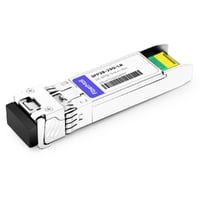
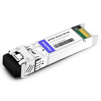
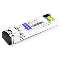
Priya had two “identical” 25G SFP28 links and zero link lights. Both modules showed normal DDM readings. The fibers tested fine. The configurations looked correct.
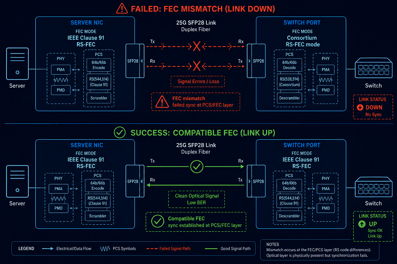
For three shifts, her team swapped optics, reseated cables, and reopened tickets. The fix, when it finally came, was a single FEC mismatch: the server NIC was configured for IEEE RS-FEC (Clause 91), while the Cisco Nexus port was using Consortium RS-FEC (rs-cons16). Neither configuration was necessarily wrong on its own. They simply did not match.
That’s the thing about sfp28 troubleshooting that most guides miss. At 25G, the module is rarely the first thing to blame. FEC mismatch, auto-negotiation, and a dirty connector cause far more failures than a bad optic does. Yet most engineers skip the physical layer, jump straight to RMA paperwork, and ship back modules that work fine.
This guide walks you through a 5-phase workflow that resolves roughly 90% of SFP28 issues in order of probability. You’ll get the vendor CLI commands for Cisco, Arista, Juniper, NVIDIA/Mellanox, and Extreme, plus the DDM thresholds and auto-negotiation fixes that actually bring 25G links up. If you need the fundamentals first, our complete SFP28 guide covers form factors, speeds, and reach.
The 5-Phase SFP28 Troubleshooting Workflow
SFP28 troubleshooting isn’t a mystery. It’s a process. Run these phases in order and you’ll avoid chasing the wrong problem.
Engineers often want to start with the most interesting step: FEC configuration, firmware upgrades, or deep BER analysis. In practice, starting with basic physical checks is usually faster.
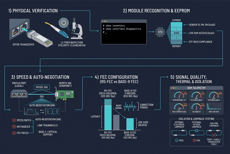
Based on typical 25G support experience, troubleshooting cases often fall into the following approximate pattern:
| Phase | Focus | Approximate Resolution Rate |
| Phase 1 | Physical Verification | ~40% |
| Phase 2 | Module Recognition & EEPROM | ~25% |
| Phase 3 | Speed & Auto-Negotiation | ~15% |
| Phase 4 | FEC Configuration | ~15% |
| Phase 5 | Signal Quality, Thermal & Isolation | ~5% |
These percentages are only approximate and will vary by environment. Storage networks, server-facing leaf ports, enterprise switches, and data center fabrics can have very different failure profiles.
The important point is the troubleshooting order: physical layer first, module recognition second, speed and negotiation third, FEC next, and deeper signal-quality analysis last.
A disciplined SFP28 troubleshooting process saves time and helps prevent unnecessary returns.
Phase 1: Physical Verification
Start with your hands.
A significant number of optical link problems originate in the physical layer, particularly from contaminated or damaged fiber connections.
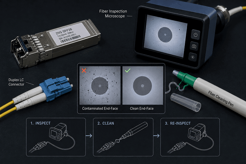
Connector contamination is widely recognized as one of the most common causes of optical link degradation. At 25G, maintaining clean connectors and sufficient optical margin is especially important. Dust, oil, scratches, or debris on an LC end face can introduce insertion loss, reflections, or intermittent link behavior.
A clean end face is one of the cheapest forms of link insurance.
Visual Inspection Checklist
- Module seating: Push until you hear the latch click. Partial insertion causes intermittent errors and flapping links.
- Golden fingers: Check for debris, corrosion, or bent pins. One bent pin kills the link.
- Connector damage: Look for cracked ferrules, pulled boots, and kinked fiber.
- Dust caps: A module that sat on a shelf without its cap is already contaminated.
The $12K RMA Cascade
A storage team I know shipped four dozen SFP28 modules back over two months. Every single one tested good on the factory bench.
The root cause was not the modules. It was contamination in the fiber path.
A technician had repeatedly inserted fresh modules into connections associated with a contaminated LC adapter. New components were installed, but the contaminated interface remained in the link.
Thousands of dollars in return shipping, labor, and downtime were ultimately traced back to a basic fiber-cleanliness problem that could have been prevented with inexpensive inspection and cleaning tools.
Clean before connecting, and inspect with a proper fiber microscope instead of relying on the naked eye.
Fiber and Media Matching
The module type has to match the fiber plant. This trips people up more often than you’d expect in sfp28 troubleshooting.
- 25GBASE-SR needs multimode fiber: OM3 reaches about 70 meters, OM4 about 100.
- 25GBASE-LR needs single-mode fiber: roughly 10 km, sometimes extended.
- 25GBASE-ER runs single-mode out to about 40 km.
Fiber type mismatch, plugging an LR module into multimode, or an SR into single-mode, gives you either no light or a link that flaps. For a full rundown of which module fits which media and reach, see our SFP28 module types guide.
QSFP28-to-SFP28 Adapters
Adapters add a variable that rarely helps. A generic QSA won’t reliably pass a 25G signal, and some switches reject adapters outright. If you must use one, match the vendor-specific part number.
Extreme, for example, references a specific SFP28 adapter part (10506) for its 100G ports. The wrong adapter shows up as a port that stays down no matter what you swap.
Cleaning Procedure
1. Inspect with a 200x or 400x fiber microscope. Never clean what you haven’t looked at.
2. Wet-to-dry: one drop of fiber cleaning fluid on a lint-free wipe, draw the connector across the wet zone, then the dry zone. UPC only, never alcohol on APC.
3. Re-inspect until the end face passes. Thirty seconds now beats hours later.
Phase 2: Module Recognition & EEPROM
Your switch might not see the module at all. SFP28 not recognized and sfp28 not detected are among the most common 25G complaints.
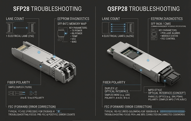
SFP28 modules use the SFF-8472 specification for their EEPROM memory map and digital diagnostics. Note the difference: QSFP28 uses SFF-8636, but SFP28 stays on the SFP family’s SFF-8472.
The EEPROM stores vendor ID, part number, serial, speed capabilities, and the diagnostic registers that DDM reads. When the switch can’t parse those bytes, the module appears invisible or “unsupported.”
Vendor Module Detection Commands
Cisco IOS-XE / NX-OS:
show interface ethernet 1/1 transceiver
show interface transceiver
show inventory
Arista EOS:
show interfaces Ethernet1/1 transceiver
show interfaces transceiver eeprom
Juniper Junos:
show interfaces diagnostics optics
show chassis hardware
Dell OS10:
show inventory media
show ddm
NVIDIA / Mellanox (Linux):
ethtool -m enp1s0
mlxlink -d mlx5_0 -m
If the module shows up with valid vendor data, recognition is fine and you move on. If it’s missing entirely, check seating and power first. If it shows “unsupported” or “third party and is disabled,” you have a vendor lock problem.
Vendor Lock and “Unsupported Transceiver”
OEM switches validate the vendor ID in the EEPROM. A third-party SFP28 coded for the target platform works fine. One that isn’t gets rejected with messages like:
- Cisco: %SFP-4-UNSUPPORTED_SENSE, or the port drops into err-disable with “transceiver is not supported”
- Juniper: Unsupported transceiver
- Arista: usually detects it but logs a warning
- Dell OS10: err-disabled port, “unsupported transceiver”
Third-party modules don’t cause most of these failures. The EEPROM coding does. That’s a fixable configuration issue, not a hardware problem.
Override commands (test in lab first, and know the warranty implications):
- Cisco: service unsupported-transceiver plus no errdisable detect cause gbic-invalid
- Arista: service unsupported-transceiver <licensee-name>
- Dell OS10: allow unsupported-transceiver
Note that Cisco tightened EEPROM validation in IOS-XE 17.12 and later on Catalyst 9000. An SFP28 that passed validation on 17.9 may be rejected after an upgrade. Before you RMA, check whether the module is coded for your platform and firmware level. Our SFP28 compatibility guide walks through EEPROM coding requirements per vendor.
The “Third Party and Is Disabled” Case
A network admin at a university called about 25G SFP28 modules that “didn’t work.” The switches refused them with a message about third-party optics being disabled. The modules were fine.
The config needed one line: service unsupported-transceiver on the Cisco side, then the ports came up in under a minute. No RMAs, no replacements. The modules had been returned and re-ordered twice before someone read the error message properly.
Not Detected Decision Tree
1. Module absent from all detection commands → reseat, check power, check the port itself.
2. Module present but garbled vendor info → EEPROM read issue, check firmware and seating.
3. Module present but “unsupported” → vendor lock, check coding and override commands.
4. Module present and recognized but no link → proceed to Phase 3.
Phase 3: Speed & Auto-Negotiation
Here’s the 25G gotcha nobody warns you about. Many platforms default auto-negotiation to “on” on 25G ports.
When the far end is hard-set to 25G, which is common on storage controllers and server NICs, the link won’t come up. Both ends are “correct.” They just can’t agree.
The Dell VxRail KB for 25 Gbps interfaces not communicating describes exactly this pattern. The fix that works consistently: disable auto-negotiation and hard-set the speed to 25G on both ends. It removes a whole class of negotiation failure modes.
Recommended baseline config:
- Set both ends to speed 25G, fixed.
- Disable auto-negotiation on the port.
- Align FEC mode (covered in Phase 4).
On Broadcom 57414-class NICs used in many 25G servers, the BIOS settings matter as much as the switch config. Set Link FEC to CL91, Operational Link Speed to 25 Gbps, and the auto-negotiation advertisement to IEEE 802.3by. A NIC left at “auto” with FEC set to “none” is a classic source of a 25G link that won’t establish.
One more check before you go deep: confirm the port actually supports 25G. An SFP28 module physically fits in an SFP+ cage, but a 10G-only port can’t run 25G no matter what you configure. If the port is capped at 10G, the module will be detected, the speed config will fail, and you’ll chase your tail. That’s a hardware capability issue, not a software one.
For the full 25G vs 10G comparison, port capability, reach, and where each makes sense, see our SFP28 vs SFP+ guide.
Phase 4: FEC Configuration
SFP28 FEC mismatch is the #1 cause of 25G link failures, and it’s the most misunderstood.
The 25GBASE-R line rate is 25.78125 Gbps, defined by IEEE 802.3by. At that speed, the signal-to-noise margin is thin. Forward Error Correction compensates by adding redundant bits that let the receiver correct bit errors on the fly.
But FEC only works if both ends agree on the same scheme. Mismatched FEC produces flapping links, high error counts, or a link that never comes up at all.
Which FEC Scheme to Use
SFP28 supports two common FEC types:
- RS-FEC (Clause 91): Reed-Solomon, used on many 25GBASE-R fiber links. Cisco calls it rs-ieee or rs-fec.
- FC-FEC / Fire Code (Clause 74): lighter-weight BASE-R FEC, often used on DAC and shorter fiber links.
There’s also the Consortium 1.6 variant, a re-configured RS-FEC that some NIC vendors and switch platforms use as a default. This is where mismatches get sneaky: the module negotiates FEC, but the two ends implement different flavors of RS-FEC.
The FEC Mismatch That Took Three Shifts
Remember Priya’s case from the top? The server NIC advertised CL91, the Cisco Nexus ran fec rs-cons16. Both are Reed-Solomon FEC. Neither is “wrong” in isolation.
The Nexus was negotiating Consortium FEC, the NIC wanted IEEE 802.3by CL91, and the two never agreed. Aligning them to the same scheme and disabling auto-negotiation brought both links up in five minutes.
FEC mismatch symptoms:
- Link flaps on a regular interval
- High pre-FEC BER with clean DDM readings
- Link establishes but traffic errors climb
- One direction works, the other doesn’t
Vendor FEC Commands
Cisco NX-OS:
interface ethernet 1/1
fec rs-cons16
speed 25000
no negotiate auto
FEC options: rs-cons16, rs-ieee, rs-fec, fc-fec, off, auto. Verify with show interface ethernet 1/1 fec. The Cisco Nexus 9000 NX-OS interfaces guide documents the full set.
Arista EOS:
interface Ethernet1/1
fec rs-fec
speed 25
no negotiation auto
Juniper Junos (per release):
set interfaces xe-0/0/0 fec rs-fec
set interfaces xe-0/0/0 speed 25g
set interfaces xe-0/0/0 link-mode full-duplex
NVIDIA / Mellanox:
mlxlink -d mlx5_0 -k NF –fec_speed 25G
ethtool –set-fec enp1s0 encoding rs
Extreme (EXOS):
configure ports 1 forward-error-correction on cl91
Extreme has shipped releases where FEC “auto” caused SFP28 links to drop after a firmware upgrade. The fix is explicit FEC config or a patched release. Worth checking your firmware notes before you blame optics.
Pre-FEC vs Post-FEC Counters
Read both. Pre-FEC errors are normal, that’s what FEC is for. Post-FEC errors are not.
| Counter | Reading | Meaning |
| Pre-FEC BER | < 10⁻⁵ | Healthy; FEC correcting normally |
| Pre-FEC BER | 10⁻⁵ to 10⁻⁴ | Degraded margin; inspect fiber and connectors |
| Pre-FEC BER | > 10⁻⁴ | Near failure; act now |
| Post-FEC errors | Zero | Correct |
| Post-FEC errors | Any non-zero | Link operating past correction capacity; will flap |
A link with post-FEC errors is living on borrowed time. It might stay up for a week or an hour. Either way, the margin is gone, and a single noise burst takes it down.
Phase 5: Signal Quality, Thermal & Isolation
When the module is recognized, the speed is right, and the FEC matches, but the link is still flaky, it’s time for the last phase of sfp28 troubleshooting: diagnostics and isolation.
DDM Parameter Interpretation
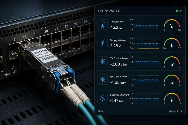
SFP28 uses SFF-8472 digital diagnostics, which give you real-time temperature, voltage, TX power, RX power, and TX bias. Know the thresholds so you can read the module instead of guessing.
| Parameter | Normal Range | Warning Sign | Action |
| Temperature | 0-70°C (commercial), -40 to +85°C (industrial) | >65°C | Check airflow and blanking panels |
| Voltage | 3.13-3.47V | Outside 3.1-3.5V | Check power supply |
| TX Power | Within module spec | >3dB below spec | Clean connectors; consider replacement |
| RX Power | Within link budget | Below receiver sensitivity | Check fiber, clean end faces |
| TX Bias | Stable baseline | >20% increase over baseline | Laser aging; plan replacement |
The TX bias trend is the earliest warning you’ll get. A laser pulling 20% more current to hold the same output power is aging. Replace it during a maintenance window, not during an outage. For a deeper treatment of DDM readings, the Wolontek DDM/DOM guide is a solid reference.
The Thermal Cascade
High temperature on an SFP28 follows a predictable chain:
1. Ambient temp rises (summer, failed HVAC, blocked airflow).
2. Module case temp crosses its limit.
3. Laser auto-shutdown triggers TX Fault.
4. Remote end sees RX LOS.
5. The switch may flag the module as failing, even though the module is fine.
We saw a 25G top-of-rack switch where the upper ports ran 8-12°C hotter than the lower ones because a missing blanking panel let exhaust air recirculate. Modules in those ports reported high temps and TX faults. Two blanking panels and a rack reflow later, the problem disappeared. What looked like three separate failures, sfp28 temperature high, tx fault, rx loss, was one airflow problem.
Loopback Testing
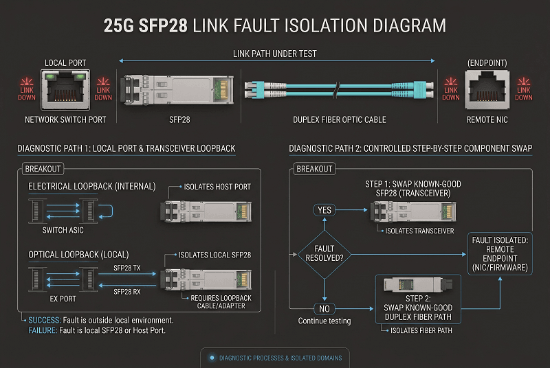
A loopback module shorts TX back to RX inside the module. It’s the fastest way to separate host-side from fiber-side issues.
When to use it:
- Port won’t come up and you need to know if the switch port is healthy
- Remote site is inaccessible and you need local verification
- You suspect a host ASIC lane problem
Expected behavior: insert the loopback, enable the port, and it comes up immediately with no fiber attached. DOM will show high RX power (that’s expected on a loop) and near-zero BER. If the port won’t come up with a loopback, the problem is host-side. If it works with a loopback but not with a real link, it’s optical or remote.
The Swap Test Decision Tree
Step 1: Move the suspect module to a known-good port. Works → original port or cable is the problem. Fails → module is suspect.
Step 2: Put a known-good module in the suspect port. Works → original module was the issue. Fails → port or cable.
Step 3: Swap the cable with a known-good spare. Works → cable. Fails → port or module.
Step 4: Repeat steps 1-2 on the remote end.
Swap one variable at a time. Replacing module and cable simultaneously destroys the diagnostic signal and turns a 10-minute isolation into an afternoon of guesswork.
SFP28 vs QSFP28 Troubleshooting: What’s Different
If you’ve used our QSFP28 troubleshooting guide, most of the workflow carries over. But a few differences matter:
- Diagnostics spec: SFP28 uses SFF-8472; QSFP28 uses SFF-8636. Different EEPROM maps, different DDM registers.
- Lane count: SFP28 is single-lane NRZ. QSFP28 is 4-lane. No lane mapping, no MPO polarity problems at 25G, just a duplex LC pair.
- FEC flavors: 25G uses RS-FEC CL91 and FC-FEC CL74, with the Consortium 1.6 variant. 100G QSFP28 primarily uses RS-FEC with KP4 at 400G. Different FEC families, different mismatch symptoms.
- The auto-negotiation gotcha: 25G ports defaulting AN to “on” is a failure mode you rarely see on QSFP28. Worth checking first.
- Speed cage confusion: SFP28 fits SFP+ cages, which creates the “module detected but can’t run 25G” trap. QSFP28-to-QSFP-DD has an analogous issue but it’s less common.
For 100G troubleshooting, our QSFP28 troubleshooting guide covers the multi-lane workflow.
SFP28 Troubleshooting Toolkit
You don’t need a lab bench to diagnose most 25G issues. Here’s what actually earns its place:
| Tool | Purpose | Approximate Cost | When to Use |
| Fiber inspection microscope (200-400x) | End-face quality check | $150-400 | Phase 1, every suspected link |
| Fiber cleaning kit (pen + wipes + fluid) | Connector cleaning | $20-50 | Phase 1, before every insertion |
| Optical power meter | Measure TX/RX levels | $200-600 | Phase 5, verify optical budget |
| SFP28 loopback module | Host-side port verification | $50-100 | Phase 5, isolate port vs. module |
| Visual fault locator | Fiber continuity check | $30-80 | Phase 1, find breaks and tight bends |
The $20 cleaning kit is the highest-ROI tool in the list. We’ve watched it prevent five-figure RMA cascades. Buy two.
Pre-Deployment Checklist
The best sfp28 troubleshooting happens before the link ever goes down. Run this before every 25G deployment:
1. Verify switch firmware supports the specific module, check release notes, not assumptions.
2. Confirm FEC matches on both ends, same scheme, explicitly configured.
3. Disable auto-negotiation and hard-set speed 25G on both ends.
4. Match fiber type to module, OM3/OM4 for SR, single-mode for LR/ER.
5. Inspect and clean every connector before insertion, including patch panels.
6. Document baseline DDM values, temperature, TX/RX power, bias current.
7. Set automated alerts, temp above 65°C, power deviation beyond 3dB, bias drift.
8. Confirm EEPROM coding for third-party modules before the deployment window.
This checklist prevents a large share of the 2 AM pages that otherwise come in as “sfp28 not recognized” tickets. It’s cheaper than one failed maintenance window.
SFP28 Troubleshooting FAQ
Why is my SFP28 not detected?
Check seating and power first, then EEPROM compatibility. SFP28 not detected is often vendor lock, not a dead module. Verify the module appears in your platform’s transceiver commands.
If it shows “unsupported,” check EEPROM coding or the vendor override command. Update switch firmware before RMAing.
Does SFP28 require FEC?
At 25G, yes in most practical deployments. IEEE 802.3by defines RS-FEC (Clause 91) and FC-FEC (Clause 74), and modern 25G links run cleaner with one enabled on both ends. The critical rule: the same scheme must be configured on both ends. Mismatched FEC is the most common cause of 25G link failure.
Can SFP28 work in an SFP+ port?
Physically, yes, the cage is the same size. But an SFP+ port is typically capped at 10G and can’t run 25G. The module gets detected, then the link fails to come up. Always confirm the port supports 25G before troubleshooting the module.
Why does my 25G link flap?
Check FEC mismatch and auto-negotiation first, then physical layer. A flapping link with clean DDM is almost always a negotiation or FEC problem. Check pre-FEC BER, align FEC on both ends, and hard-set speed to 25G.
How far can 25GBASE-SR reach over OM4?
About 100 meters over OM4 and roughly 70 meters over OM3. Beyond that, use 25GBASE-LR on single-mode fiber, which reaches about 10 km. Over-runs at the edge of the OM4 budget are a common cause of marginal 25G links.
What does “third party and is disabled” mean?
The switch’s EEPROM check rejected a non-OEM module. It’s a coding or policy issue, not necessarily a hardware fault. On Cisco, service unsupported-transceiver plus disabling err-disable detection for the module type usually resolves it. Confirm warranty implications before applying it in production.
Key Takeaways
Priya’s team now checks FEC before they check anything else. That one habit saved them a third return cycle and a lot of late-night escalations.
Here’s what to remember from this sfp28 troubleshooting guide:
- The module is usually the last thing to replace, not the first. Most 25G failures are FEC mismatch, auto-negotiation, or dirty connectors.
- Forty percent of cases resolve in the physical layer. Clean, inspect, reseat before you touch a config.
- FEC must match on both ends. RS-FEC, FC-FEC, and Consortium 1.6 are not interchangeable.
- Disable auto-negotiation and hard-set 25G. It removes a whole class of failure modes, especially against storage controllers and server NICs.
- DDM trends predict failures. Watch TX bias and temperature. Replace during maintenance, not during outages.
SFP28 troubleshooting at 25G is discipline, not magic. The modules are mature, the protocols are defined, and the failure patterns are predictable once you know them. Work the phases in order, use the right command at each step, and you’ll resolve most 25G link issues in under 30 minutes.
If you need properly EEPROM-coded SFP28 transceivers for your environment, browse our 25G SFP28 modules. We test every module against major switch platforms before shipment and can code EEPROMs for your specific vendor. Or contact FiberMall and talk to an engineer about your deployment.
For the broader SFP28 picture, speeds, form factors, and pricing, our SFP28 transceiver guide and SFP28 price guide cover the fundamentals.
Related Products:
-
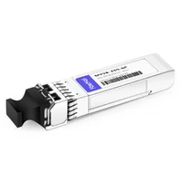
 SFP28-25G-SR 25G SFP28 SR 850nm 100m LC MMF DDM Transceiver Module
$25.00
SFP28-25G-SR 25G SFP28 SR 850nm 100m LC MMF DDM Transceiver Module
$25.00
-
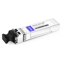
SFP28-25G-ESR 25G SFP28 ESR 850nm OM3 200m/OM4 300m LC MMF DDM Transceiver Module
$35.00
-
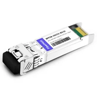
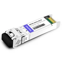
SFP28-25G32-BX10 25G BX BIDI SFP28 TX1330nm/RX1270nm 10km LC SMF DDM Transceiver Module
$42.00
-
SFP28-25G23-BX10 25G BX BIDI SFP28 TX1270nm/RX1330nm 10km LC SMF DDM Transceiver Module
$42.00
-
SFP28-25G-LR 25G SFP28 LR 1310nm 10km LC SMF DDM Transceiver Module
$45.00
-
SFP28-25G32-BX10I 25G BX BIDI SFP28 TX1330nm/RX1270nm 10km LC SMF DDM Industrial Transceiver Module
$50.00
-
SFP28-25G23-BX10I 25G BX BIDI SFP28 TX1270nm/RX1330nm 10km LC SMF DDM Industrial Transceiver Module
$50.00
-
SFP28-25G32-BX03C 25G BX BIDI SFP28 TX1330nm/RX1270nm 300m LC SMF DDM Transceiver Module
$58.00
-
SFP28-25G23-BX03C 25G BX BIDI SFP28 TX1270nm/RX1330nm 300m LC SMF DDM Transceiver Module
$58.00
-
SFP28-25G-ER 25G SFP28 ER 1310nm 40km LC SMF DDM Transceiver Module
$125.00
-
SFP28-25G32-BX40 25GBASE SFP28 BIDI ER TX1310nm/RX1270nm 40km LC SMF DDM Optical Transceiver Module
$180.00
-
SFP28-25G23-BX40 25GBASE SFP28 BIDI ER TX1270nm/RX1310nm 40km LC SMF DDM Optical Transceiver Module
$180.00