When assessing the performance of a network, we can evaluate it from four aspects: bandwidth, latency, jitter, and packet loss.
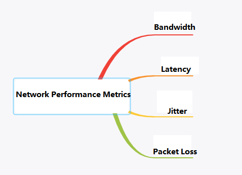
Network Performance Metrics
Bandwidth
Concept: Bandwidth is defined in Baidu Baike as the “highest data rate” that can pass from one point to another in a network within a unit of time.
In computer networks, bandwidth refers to the highest data rate that the network can pass, which is how many bits per second (commonly measured in bps).
To put it simply, bandwidth can be likened to a highway, indicating the number of vehicles that can pass through in a unit of time.
Representation: Bandwidth is typically expressed in bps, indicating how many bits per second;
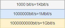
When describing bandwidth, “bits per second” is often omitted. For example, a bandwidth of 100M is 100Mbps, where Mbps stands for megabits per second.
However, the speed at which we download software is measured in Byte/s (bytes per second). This involves the conversion between Bytes and bits. In the binary number system, each 0 or 1 is a bit, which is the smallest unit of data storage, and 8 bits make up one byte.
When subscribing to broadband services, a bandwidth of 100M refers to 100Mbps. The theoretical network download speed is only 12.5MBps, but in reality, it may be less than 10MBps. This discrepancy is due to various factors such as the performance of the user’s computer, the quality of network equipment, resource usage, peak network times, the capability of website services, line degradation, signal attenuation, etc. As a result, the actual network speed cannot reach the theoretical speed.
Latency
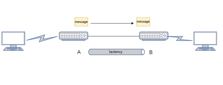
Latency, simply put, is the time it takes for a message to travel from one end of the network to the other.
For example, when I ping Google’s address on my computer;
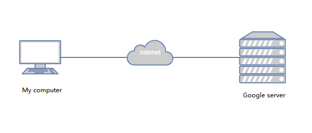
The result shows a latency of 12ms. This latency refers to the round-trip time the ICMP message needs to travel from my computer to Google’s server and back.
(Ping refers to the round-trip time it takes for a data packet to be sent from the user’s device to a test point and then immediately back to the user’s device. It is commonly known as network delay and is measured in milliseconds, ms.)
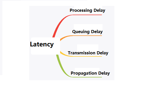
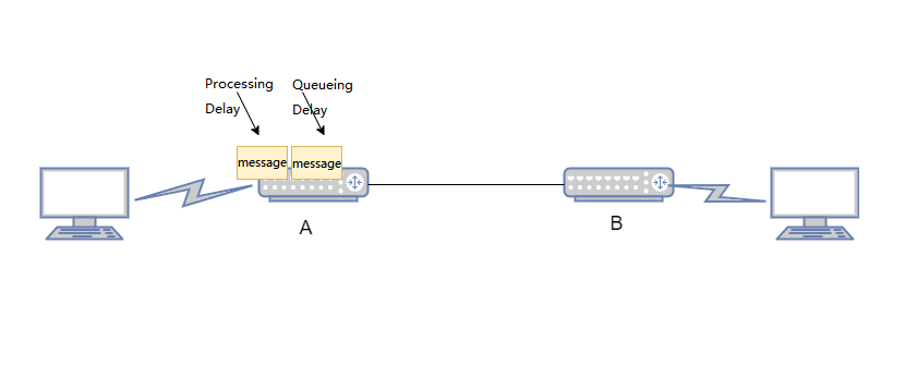
Network latency includes four main components: processing delay, queuing delay, transmission delay, and propagation delay. In practice, we mainly consider transmission delay and propagation delay.
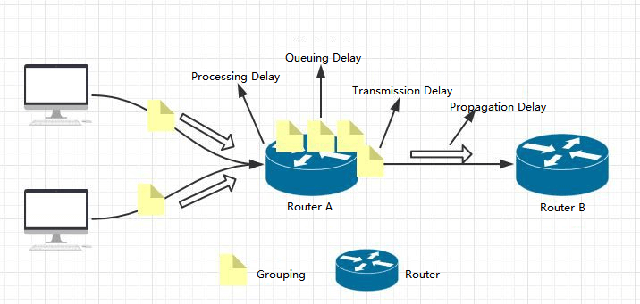
Processing Delay: Network devices such as switches and routers require a certain amount of time to process packets upon receipt. This includes tasks such as decapsulation, header analysis, data extraction, error checking, and route selection.
Typically, the processing delay for high-speed routers is on the order of microseconds or even less.

Queueing Delay: Queueing delay refers to the time spent by packets in a queue while being processed by network devices like routers or switches.
The queueing delay for a packet depends on whether there are other packets currently being transmitted in the queue.
If the queue is empty and no other packets are being transmitted, the queueing delay for the packet is zero. Conversely, if there is heavy traffic and many other packets are also waiting for transmission, the queueing delay can be significant.
Actual queueing delays are usually in the range of milliseconds to microseconds.
Transmission Delay: Transmission delay is the time it takes for routers and switches to send data, which is the time needed for the router’s queue to deliver the packet to the network link.
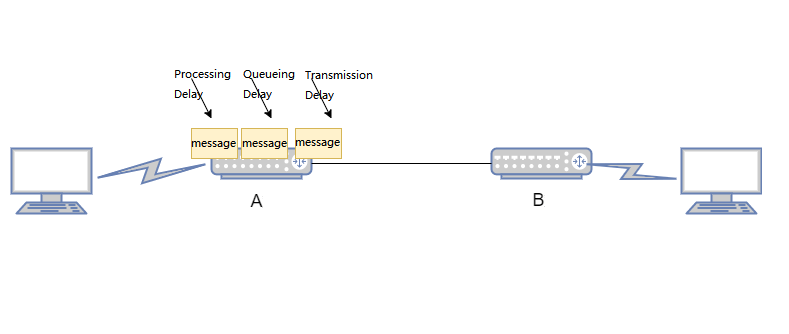
If (L) represents the length of the packet in bits, and (R) represents the link transmission rate from router A to router B in bits per second (bps), then the transmission delay is L/R.
Actual transmission delays are typically in the range of milliseconds to microseconds.
Propagation Delay: Propagation delay is the time it takes for a message to travel through the physical link between two routers.
The propagation delay is equal to the distance between the two routers divided by the propagation speed of the link, denoted as (D/S), where (D) is the distance between the two routers, and (S) is the propagation speed of the link.
Actual propagation delays are on the order of milliseconds.
Understanding these delays is crucial for optimizing network performance and ensuring efficient data transmission.
Jitter
Jitter in networking refers to the variation in time delay between packets arriving, caused by network congestion, timing drift, or route changes. For example, if the maximum delay experienced when accessing a website is 10ms and the minimum delay is 5ms, then the network jitter is 5ms.
A jitter is used to evaluate the stability of a network; the smaller the jitter, the more stable the network is.
This is particularly important in online gaming, where high network stability is required to ensure a good gaming experience.
Causes of Network Jitter: Network jitter can occur when there is congestion in the network, leading to variable queueing delays that affect the end-to-end latency. This can cause the delay between Router A and Router B to fluctuate, resulting in network jitter.
Packet Loss
Packet loss occurs when one or more data packets fail to reach their destination across a network. If the receiving end detects missing data, it will request a retransmission of the lost packets based on their sequence numbers.
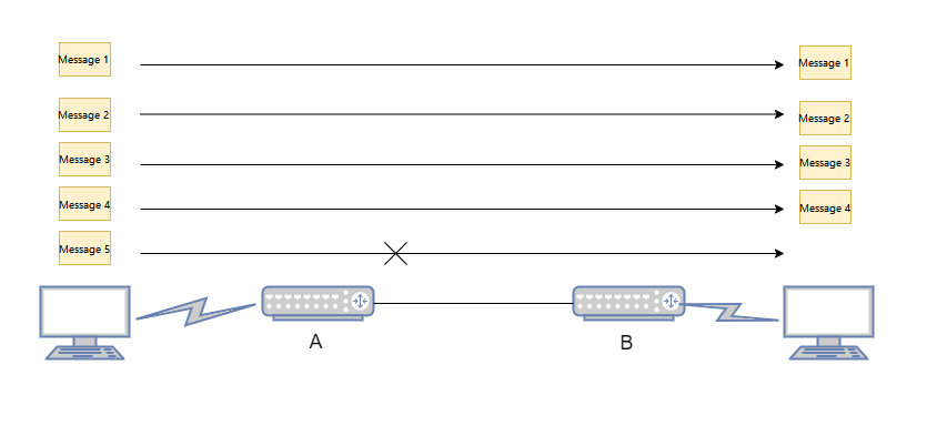
Packet loss can be caused by several factors, with network congestion being one of the most common. When the data traffic is too heavy for the network equipment to handle, some packets may inevitably be lost.
Packet Loss Rate: The packet loss rate is the ratio of the number of data packets lost during a test to the total number of packets sent. For instance, if 100 packets are sent and one packet is lost, the packet loss rate is 1%.
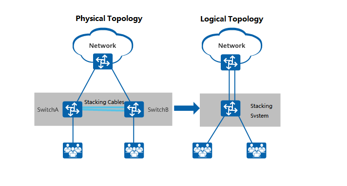
Stacking: Stacking refers to the practice of connecting multiple switches that support stacking features using stacking cables, logically virtualizing them into a single switch device that participates in data forwarding as a whole. Stacking is a widely used horizontal virtualization technology that offers benefits such as improved reliability, expanded port numbers, increased bandwidth, and simplified network configuration.
Why is stacking needed?
Traditional campus networks use device and link redundancy to ensure high reliability, but their link utilization is low and network maintenance costs are high. Stacking technology virtualizes multiple switches into a single switch to simplify network deployment and reduce network maintenance workload. Stacking has many advantages:
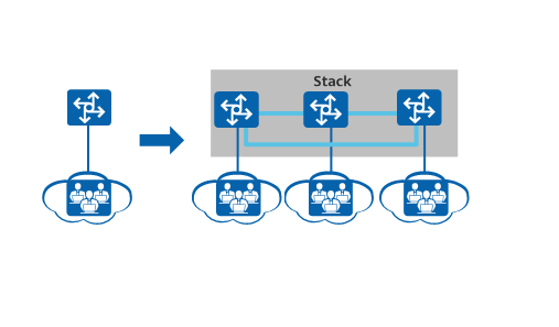
Enhanced Reliability: Stacking allows multiple switches to form a redundant backup system. For instance, if Switch A and Switch B are stacked together, they back each other up. If Switch A fails, Switch B can take over to ensure the system continues to operate normally. Additionally, stacked systems support cross-device link aggregation, which also provides redundancy for the links.
Stacking Schematic
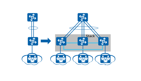
Expanded Port Numbers: When the number of users exceeds the port density that a single switch can handle, new switches can be added to the existing one to form a stacked system, thereby expanding the number of available ports.
Expansion Port Number Schematic
Increased Bandwidth: To increase the uplink bandwidth of a switch, new switches can be added to form a stacked system. Multiple physical links of member switches can be configured into an aggregation group to enhance the switch’s uplink bandwidth.
Increased Bandwidth
Simplified Network Configuration: In a stacked network, multiple devices are virtually configured as a single logical device. This simplification eliminates the need for protocols like MSTP to break loops, streamlines network configuration, and relies on cross-device link aggregation to achieve quick fail-over in case of a single device failure, thus improving reliability.
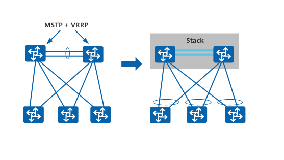
Simplified Network Configuration
Long-Distance Stacking: Users on each floor can access the external network through corridor switches. By connecting corridor switches that are far apart to form a stack, it effectively turns each building into a single access device, simplifying the network structure. Each building has multiple links to the core network, making the network more robust and reliable. Configuring multiple corridor switches is simplified to configuring the stacked system, reducing management and maintenance costs.
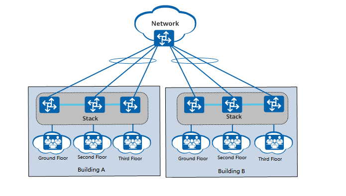
Long-Distance Stacking
Devices that Support Stacking
Most mainstream switches support stacking. For example, Huawei’s S series campus switches and CloudEngine data center switches have models that support stacking. For the S series campus switches, only box-type switches support stacking; two chassis-type switches together form a cluster. For CloudEngine data center switches, both chassis-type and box-type switches have models that support stacking, with the difference being that chassis-type switches only support stacking of two devices.
Stack Establishment Concepts
In a stacking system, all individual switches are referred to as member switches. Based on their functions, they can be categorized into three roles:
Master Switch: The master switch is responsible for managing the entire stack. There is only one master switch in a stacking system.
Standby Switch: The standby switch acts as a backup for the master switch. There is only one standby switch in a stacking system. It takes over all operations of the original master switch in case of a failure.
Slave Switches: Slave switches are used for business traffic forwarding. There can be multiple slave switches in a stacking system. The more slave switches there are, the greater the forwarding bandwidth of the stack.
All member switches, except for the master and standby switches, are slave switches. A slave switch assumes the role of a standby switch when the latter is unavailable.
Stack ID
The stack ID is used to identify member switches within the stack, representing the slot number of the member switch. Each member switch has a unique stack ID in the system.
Stack Priority
Stack priority is an attribute of member switches, mainly used during the role election process to determine the role of member switches. The higher the priority value, the higher the likelihood of being elected as the master switch.
Stack Establishment Process
The process of establishing a stack includes the following four stages:
- Based on network requirements, select the stacking cables and connection methods. Different products support different physical connection methods. For S series campus box switches and CloudEngine data center box switches, chain and ring connection topologies are supported. For CloudEngine data center chassis switches, SIP port connections and service port connections are supported.
- Elect the master switch. After all member switches are powered on, the stacking system begins the election of the master switch. Each member switch in the stacking system has a defined role, with the master switch managing the entire stack.
- Assign stack IDs and elect the standby switch. After the master switch election is complete, it collects topology information from all member switches, calculates the stack forwarding table entries, distributes them to all member switches, and assigns stack IDs. Subsequently, the election for the standby switch takes place to serve as a backup for the master switch. The switch that completes the device startup first, other than the master switch, is prioritized as the standby switch.
- Synchronize software versions and configuration files. After the role election and topology collection are completed, all member switches automatically synchronize the software version and configuration file of the master switch.
- The stacking system can automatically load system software. Member switches forming a stack do not need the same software version; they only need to be compatible. If the software version of the standby or slave switch differs from that of the master switch, the standby or slave switch will automatically download the system software from the master switch, restart with the new system software, and rejoin the stack.
- The stacking system also has a configuration file synchronization mechanism. The master switch saves the configuration file for the entire stack and manages the configuration of the entire system. The standby or slave switches synchronize the configuration file from the master switch to their switch and execute it. This ensures that multiple devices in the stack can work as a single device in the network, and in the event of a master switch failure, the remaining switches can still perform all functions normally.
Introduction to SFP (SFP+) Optical Modules
Optical modules and switches are indispensable in common network projects, such as enterprise network deployment and data center construction. Optical modules primarily convert electrical signals into optical signals, while switches facilitate the forwarding of these optoelectronic signals. Among the various optical modules available, SFP+ modules are one of the most widely used today. Different connection methods with switches can meet various network requirements.
What is the SFP+ Optical Module
SFP+ optical module is a type of 10G fiber module within the SFP family, independent of communication protocols. Typically connected to switches, fiber routers, and fiber network cards, it is used in 10G bps Ethernet and 8.5G bps fiber channel systems to meet the higher rate demands of data centers and facilitate network expansion and conversion.
SFP+ modules offer high-line card density and compact size, allowing for interoperability with other types of 10G modules. This provides data centers with higher installation density and cost savings, making them a mainstream pluggable optical module in the market.
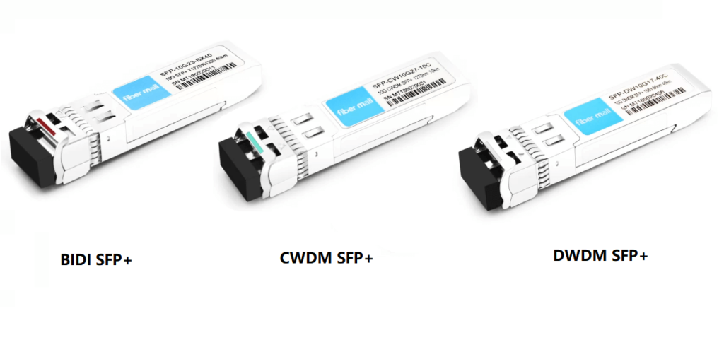
Types of SFP+ Optical Modules
Generally, SFP+ optical modules are categorized based on their actual applications. Common types include 10G SFP+, BIDI SFP+, CWDM SFP+, and DWDM SFP+ modules.
10G SFP+ Modules: These are standard SFP+ modules, considered an upgraded version of 10G SFP modules, and are a mainstream design in the market.
BIDI SFP+ Modules: Utilizing wavelength division multiplexing technology, these modules have a rate of up to 11.1G bps and low power consumption. With two fiber optic ports, they are typically used in pairs, reducing the amount of fiber used and construction costs in data center network construction.
CWDM SFP+ Modules: Employing coarse wavelength division multiplexing technology, these modules are often used with single-mode fibers, saving fiber resources and offering flexibility and reliability in networking, with low power consumption.
DWDM SFP+ Modules: Using dense wavelength division multiplexing technology, these modules are often used for long-distance data transmission, with a maximum distance of up to 80km. They feature high rates, large capacity, and strong scalability.
How to Pair SFP+ Optical Modules with Switches
Different types of optical modules can be connected to switches for various networking solutions. Below are several practical application scenarios for pairing SFP+ optical modules with switches.
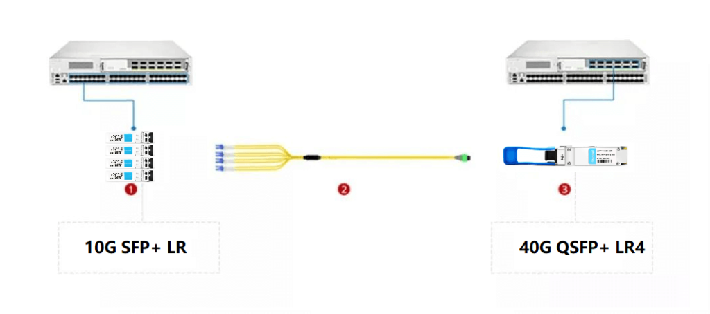
Solution 1: Connection between 10G SFP+ Optical Modules and Switches
Insert four 10G SFP+ optical modules into the 10Gbps SFP+ ports of one switch, and then insert a 40G QSFP+ optical module into the 40Gbps QSFP+ port of another switch. Finally, connect them in the middle with a breakout fiber optic jumper. This connection method mainly achieves network expansion from 10G to 40G, which can quickly and conveniently meet the network upgrade needs of data centers.
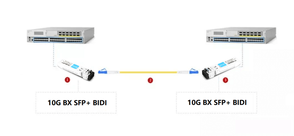
Solution 2: Connection between BIDI SFP+ Optical Modules and Switches
Insert the optical modules into the SFP+ ports of two switches, and then use LC fiber optic jumpers corresponding to the module ports to connect the optical modules on both switches. This connection method effectively achieves the simplest and most economical data connection, applicable to Ethernet connections in data centers, enterprise cabling, and telecom operator transmission.
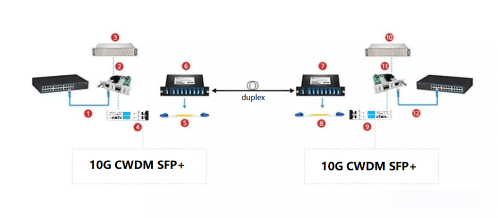
Scenario 3: Connection between CWDM SFP+ Optical Modules and Switches
This connection method uses repeater, fiber optic transceivers, and CWDM to connect the optical modules with the switches, converting the RJ45 electrical ports on the 10G Ethernet switches to the CWDM wavelengths required by the CWDM multiplexers.
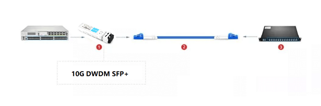
Scenario 4: Connection between DWDM SFP+ Optical Modules and Switches
Insert the optical modules into the SFP+ ports of the switches, and then use armored fiber optic jumpers to connect them with the DWDM. This connection method protects the optical signals during long-distance transmission, significantly reducing optical wave loss, and is suitable for long-distance optical signal transmission.
Precautions for Connecting SFP+ Optical Modules with Switches
- Ensure that the wavelength and transmission distance of the optical modules used by both switches are the same, as well as whether they are single-fiber or dual-fiber, single-mode or multi-mode. If there is a mismatch, use the corresponding converter.
- When using optical modules, try to avoid static electricity and bumps. If a bump occurs, it is not recommended to continue using the module.
- Pay attention to the orientation of the optical module insertion; the pull ring and label should face upwards.
- When inserting the optical module into the switch, push it firmly to the bottom. There will generally be a slight vibration. After insertion, lightly pull on the module to check if it is properly installed.
- When disassembling the optical module, first pull the ring to a position 90 degrees to the port, then remove the module.
Related Products:
-
 SFP-10G31-LRI 10G SFP+ LR 1310nm 10km LC SMF DDM Industrial High Temperature Transceiver Module
$20.00
SFP-10G31-LRI 10G SFP+ LR 1310nm 10km LC SMF DDM Industrial High Temperature Transceiver Module
$20.00
-
SFP-10G85-SRI 10G SFP+ SR 850nm 300m LC MMF DDM Industrial High Temperature Transceiver Module
$13.00
-
SFP-10G55-ZR120 10G SFP+ ZR 1550nm 120km LC SMF DDM Transceiver Module
$400.00
-
SFP-10G45-BX100 10G BX SFP+ BIDI TX1490nm/RX1550nm 100km LC SMF DDM Transceiver Module
$650.00
-
SFP-10G23-BX70 10G BX SFP+ BIDI TX1270nm/RX1330nm 70km LC SMF DDM Transceiver Module
$100.00
-
SFP-10G54-BX80 10G BX SFP+ BIDI TX1550nm/RX1490nm 80km LC SMF DDM Transceiver Module
$300.00
-
SFP-CW10G47-100C 10G CWDM SFP+ 1470nm 100km LC SMF DDM Transceiver Module
$280.00
-
SFP-CW10G47-80C 10G CWDM SFP+ 1470nm 80km LC SMF DDM Transceiver Module
$180.00
-
SFP-CW10G27-60C 10G CWDM SFP+ 1270nm 60km LC SMF DDM Transceiver Module
$105.00
-
SFP-DW10G17-40C 10G DWDM SFP+ C17 100GHz 1563.86nm 40km LC SMF DDM Transceiver Module
$155.00
-
SFP-DW10G17-80C 10G DWDM SFP+ C17 100GHz 1563.86nm 80km LC SMF DDM Transceiver Module
$175.00
-
SFP-DW10G17-100C 10G DWDM SFP+ C17 100GHz 1563.86nm 100km LC SMF DDM Transceiver Module
$235.00