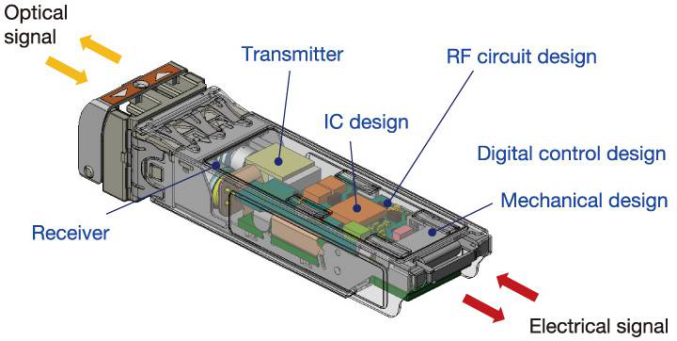
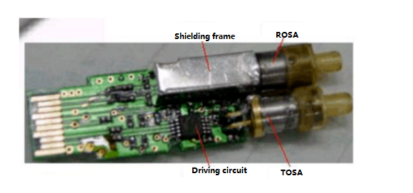
1. Schematic Diagram of the SFP/SFP+ Optical Transceivers
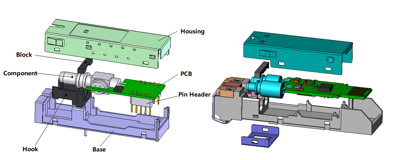
2. Bill of Material
| Material Name | Specification | |
|---|---|---|
| 1 | Housing | |
| 2 | Duplex LC Interface | |
| 3 | Optical Transmitter | Uncooled DFB Lasers |
| 4 | Optical Receiver | APD devices |
| 5 | PCB |
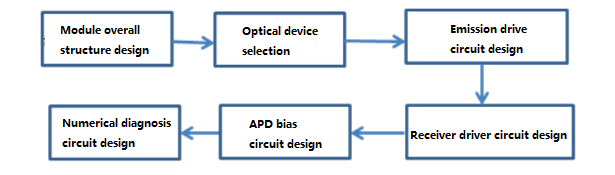
3. Components Design Ideas
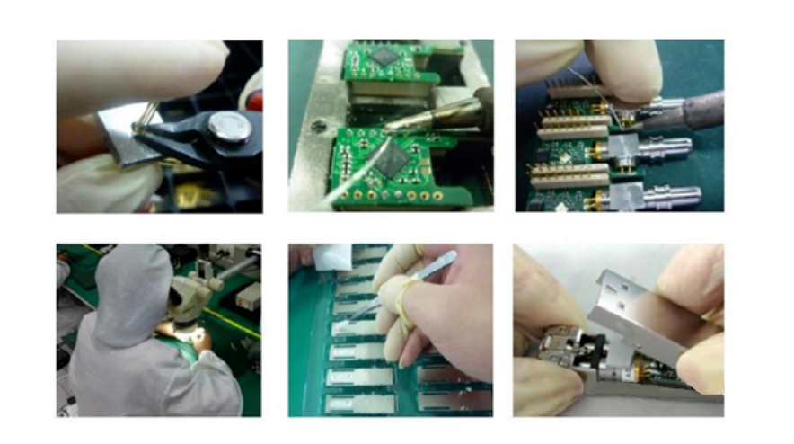
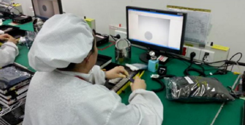
4. Optical Transceivers Assembly
- Assembly: device pin cutting, pin soldering, device pin cutting, pin soldering, flexible tape soldering, device soldering, assembly inspection, etc.
- Debugging: fixed information writing, initialization, transmitting performance adjustment, receiving performance adjustment, etc.
- Aging: power aging or baking
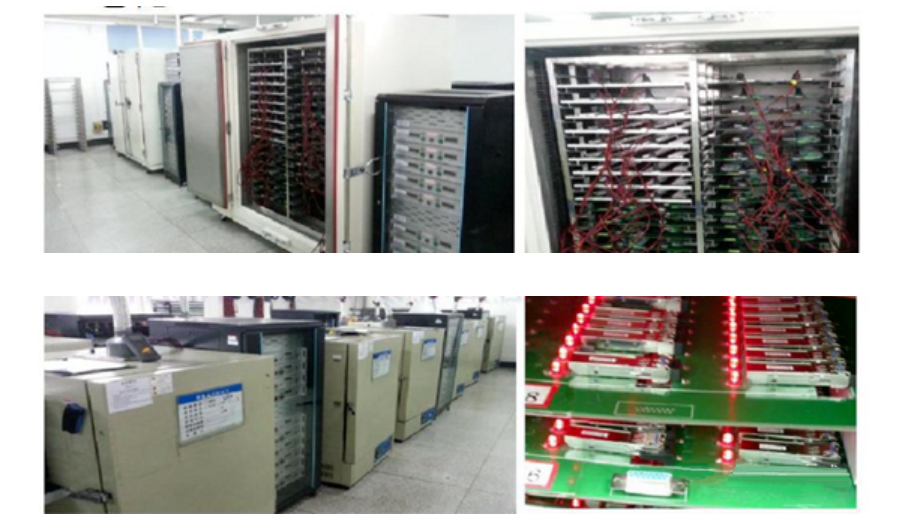
- Final test: room temperature final test, high and low-temperature final test, full temperature burst test, etc.
- Final inspection: end-face inspection, appearance inspection, data inspection
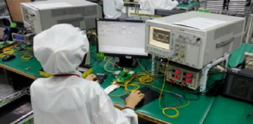
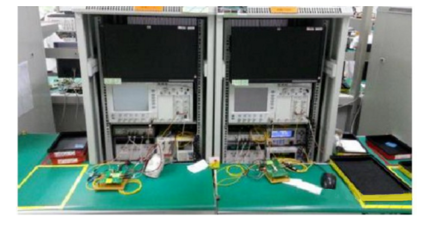
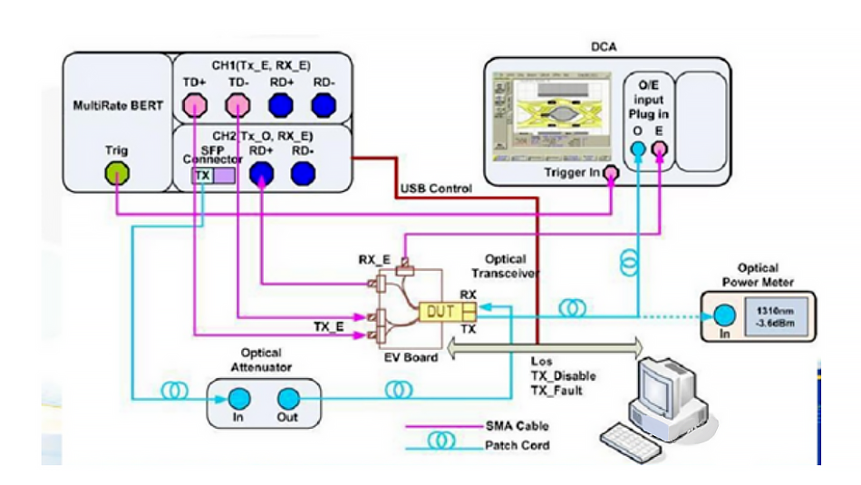
5. Optical Transceivers Testing
Equipment: BER, spectrometer, oscilloscope, DC-regulated power supply, spectrometer, and single-mode adjustable attenuator.
- Emission eye diagram:
Definition: Input the output light to the vertical amplifier of the oscilloscope, synchronize the sawtooth wave period that generates the horizontal scan with the code element timing, then the image similar to the human eye can be observed on the oscilloscope screen, called the eye diagram.
- Extinction ratio: Er
Definition: The logarithm of the ratio of the output optical power when the logic “1” is high to the output optical power when the logic “0” is low under full modulation conditions.
- Side Mode Rejection Ratio: SMSR
Definition: The ratio of the maximum power (or amplitude) of the main longitudinal mode emitted by the SLM laser to the maximum longitudinal mode power (or amplitude) of its neighbors under the worst reflection condition and full modulation.
- Spectral width: △λ
Definition: The root-mean-square (RMS) spectral width is the RMS width of the spectral distribution of the light-emitting device measured under standard operating conditions. -The 20dB spectral width refers to the wavelength interval corresponding to the two sides of the spectral line when the peak wavelength emitted by the laser decreases by 20dB at the maximum under standard operating conditions.
- Reception sensitivity: Pr
Definition: Under a certain BER condition, the minimum input average optical power that can be received by the receiving component.
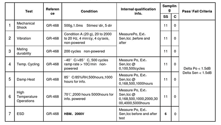
6. Optical Transceivers Reliability Test