The fifth-generation mobile communication (5G) technology has been commercially deployed for three years and has entered a critical period of large-scale application. The carrier optical module has an important impact on the transmission performance of mobile communication networks. As the 5G construction continues to advance and the application scenarios become richer, the industry continues to explore new 5G fronthaul, middlehaul, and backhaul optical module technology research to meet the demand for larger bandwidth, higher performance, lower cost, and smaller size, and to fully prepare for Beyond 5G and even 6G deployment.
FiberMall has conducted detailed research on optical module technologies for 5G bearer, data center, and all-optical access applications, and some of the solutions have been gradually matured and applied to scale. FiberMall combines the core requirements of next-generation 5G bearer optical modules, researches new technology solutions, evaluates the productization capability of 5G bearer optical modules and core optoelectronic chip devices, puts forward subsequent development suggestions, and promotes the coordinated and orderly development of next-generation 5G bearer optical module industry chain.
With the rapid rise in mobile Internet traffic, 5G network construction and optimization will continue to advance. Richer spectrum resources will also be released to drive the iterative evolution of bearer technology to meet the increasingly prominent demand for high-speed data interconnection.

Figure 1. 5G fronthaul bearer demand evolution
At present, the 5G middlehaul and backhaul access and convergence layers mainly use 25G, 50G, and 100G optical modules. The next generation 5G middlehual and backhaul network will continue to evolve towards higher speed, high capacity, low power consumption, low latency, and low cost such as 200G. In application scenarios where fiber resources are relatively tight, single-fiber bidirectional optical modules can save 50% of fiber resources compared to dual-fiber bidirectional optical modules. The 100G BiDi optical module with the advantages of good delay symmetry has become one of the research hotspots in the industry. In addition, FiberMall has researched 100G QSFP28 optical modules with 80km transmission distance. In order to reduce the cost and expand the application scope, the industry has started to layout 100G QSFP28 optical modules with more than 80km transmission distance and O-band WDM optical modules and other technology research.
100G QSFP28 and SFP112 Optical Modules
FiberMall considers 100G and other rates for next-generation 5G forwarding optical modules, but the research progress is relatively limited. The early 100G intensity modulated optical modules are mainly used in data centers and metro areas with 4x25G NRZ scheme in the form of QSFP28 package, which has a number of channels and relatively complex process. With the gradual maturity of PAM4 technology and 50GBaud optoelectronic chip devices, the 100G rate can be achieved through a single channel to simplify the packaging process and reduce costs. For 10km transmission distance, the industry has a single-channel 100Gb QSFP28 LR1 optical module with internal integration of DSP chip. FiberMall has launched 100G QSFP28 LR1 optical module products.
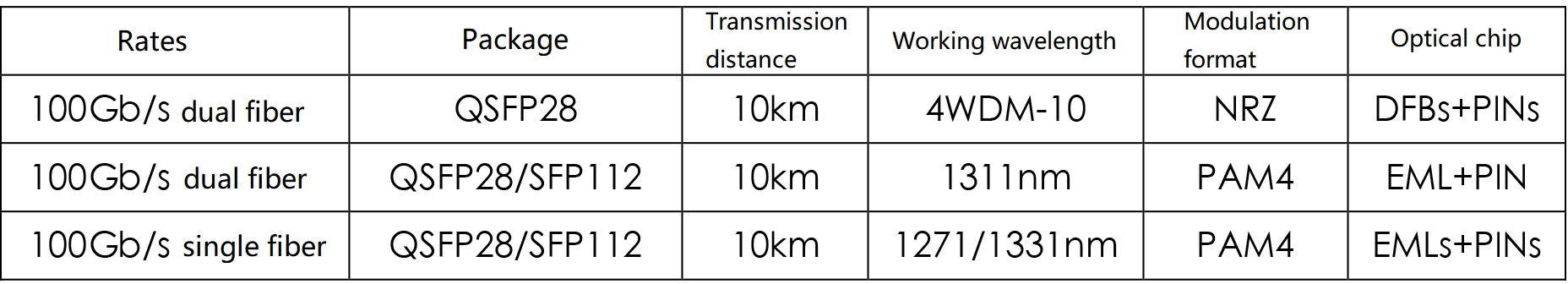
Table 1. Potential technology solutions for next-generation 5G fronthaul 100G transceivers
100G BiDi QSFP28 Optical Module
50G SFP56 BiDi optical module has been applied in the 5G medium backhaul access layer. 100G QSFP28 BiDi optical module has potential application scenarios in next-generation 5G fronthaul, middlehaul, and backhaul access and aggregation layer, data center interconnection, etc. 100G QSFP28 BiDi optical module is based on single-wave 100G PAM4 modulation code type, which has fewer devices and lower power consumption than traditional 4-channel 100G QSFP28 optical module. The 100G QSGP28 BiDi optical module is based on a DSP solution compared to the 50G SFP56 BiDi optical module, but the former has a better bit of cost and power consumption. The technical solutions of 100G QSFP28 BiDi optical module are shown in Table 2.
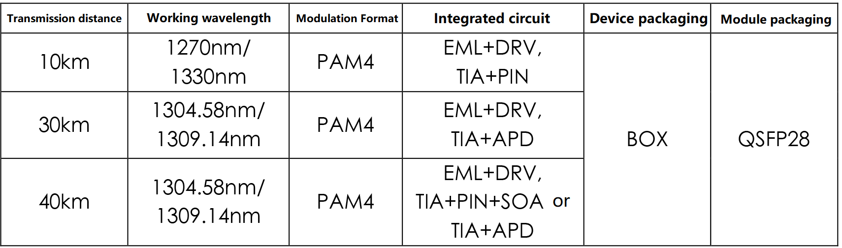
Table 2. 100G QSFP28 BiDi optical module technology solution
The PAM4 electrical signal is input to the BOSA and drives the EML laser to emit a single 100G PAM4 optical signal. In the receiving direction, the single optical signal is converted into 100G PAM4 electrical signal after BOSA, and then converted into four 25G NRZ electrical signals by DSP for signal processing and input to the system equipment.
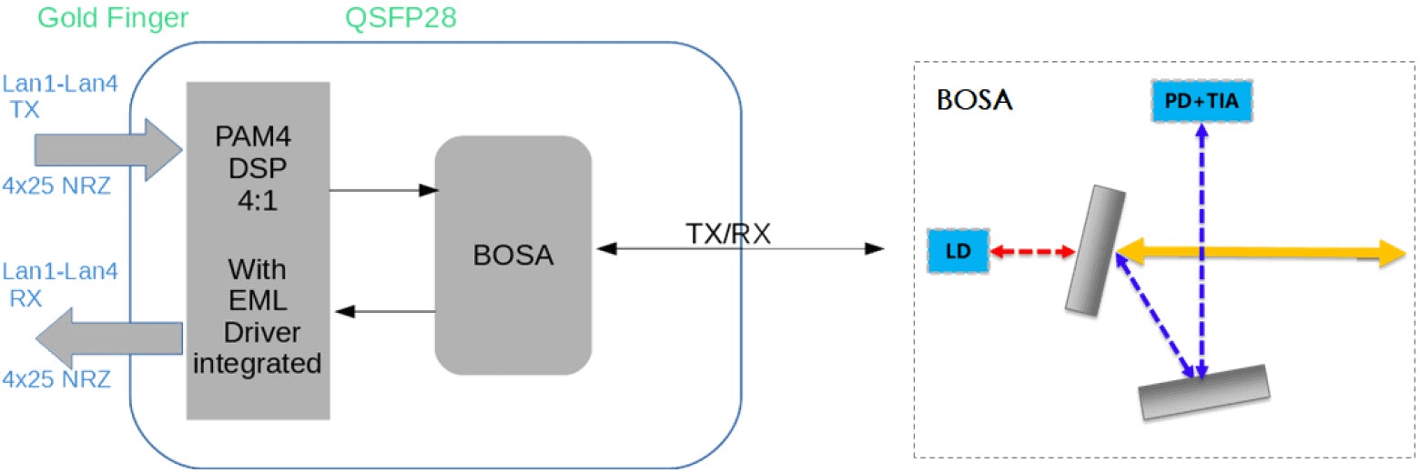
Figure 2. Single Lambda 100G QSFP28 BiDi optical module functional block diagram and BOSA technology solution
From the perspective of transmission distance, the technical specifications of 100G QSFP28 BiDi 10km optical module are less stressful for the optional solution, and the link budget is easy to achieve. However, the device packaging is mainly BOX, and the TO packaging process is not yet mature and cannot be realized in mass production. The 100G QSFP28 BiDi 30km and 40km optical modules have high requirements for OMA at the transmitter and sensitivity at the receiver, which are difficult to achieve based on the current device level and require further key technologies, such as optimizing the process at the transmitter to improve the power coupling efficiency and increasing the sensitivity margin at the receiver to reduce the yield rate in mass production. The wavelength selection of 100G QSFP28 BiDi module has not yet reached a consensus in the industry due to technical specifications and dispersion limitations, and there is uncertainty in the evaluation and screening of laser chips, and the industry chain is not yet mature.
In the international standardization, IEEE802.3 and OIF have been 100G QSFP28 optical module of the high-speed electrical interface to do the relevant specifications.
In terms of optical interface, IEEE802.3, and 100G Lambda MSA have successively released 100G QSFP28 Single Lambda 10km,20km,30km, and 40km dual-fiber bidirectional optical module standards, which regulate key indicators such as link budget, optical power, extinction ratio, sensitivity, etc. 100G QSFP28 BiDi optical IPEC has established the 100G QSFP28 BiDi 30km,40km standard project in April 2022, and IEEE802.3 has established the super 50G BiDi standard project in 2022.
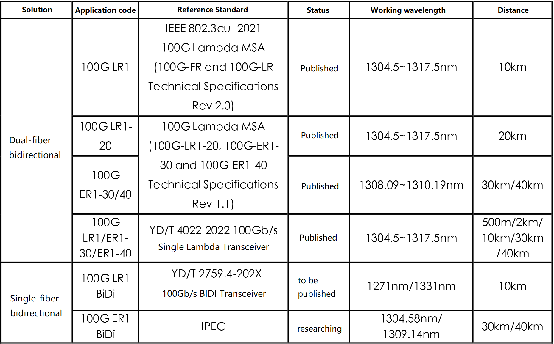
Table 3. Standardization progress of 100G QSFP28 Single Lambda 10km and above distance
The following difficulties exist in testing and verification of 100G QSFP28 BiDi optical modules: Since the transmit wavelengths of BiDi optical modules are different, the transmitter side of each wavelength needs to be tested separately, including parameters such as center wavelength, average output optical power, extinction ratio, TDECQ, OMAouter, overshoot/undershoot, and maximum conversion time. Meanwhile, the reception characteristics such as BER and sensitivity of the bidirectional transmission link may also differ and need to be tested separately.
There are different test methods for sensitivity. There are different test methods for sensitivity. First, by referring to the 100G Lambda MSA 100G-LR1/ER1 specification, the optical sensitivity power of the link is measured with the reference transmitter TECQ and compared according to the TECQ value selection formula. The second is to perform a pressure reception sensitivity test by calibrating the optical pressure signal after the SECQ parameters. The former is relatively simple, but the test results may be influenced by different reference transmitters and produce systematic bias. The latter test is more consistent, but requires higher repeatability for pressure eye calibration.
In terms of core chip devices, 100G QSFP28 BiDi optical modules can share the 100G QSFP28 Single Lambda optical module industry chain. Several manufacturers have released relevant optoelectronic chips, but there are still some key technologies to break through. Specifically, 53GBaud EML lasers need to have high bandwidth, high extinction ratio and large output power characteristics. If the 25GBaud EML laser is screened, the yield is low. New optimization in chip structure design, material doping, etc. is needed to solve the problem of securing reliability while increasing bandwidth. Chip manufacturers have already initiated design and investment. The 53GBaud PIN and APD detectors have been mass-produced. 50G rate samples are available for DSP, with good test performance, and 100/400G rates are in the R&D stage.
The main bottleneck in the future is not the product design, but the high-precision manufacturing process. The adoption of solutions that integrate multiple discrete chip devices (such as DSP integrated drivers, etc.) will help manufacturers to achieve faster replacement by using the same manufacturing process and focusing resources on breakthroughs.
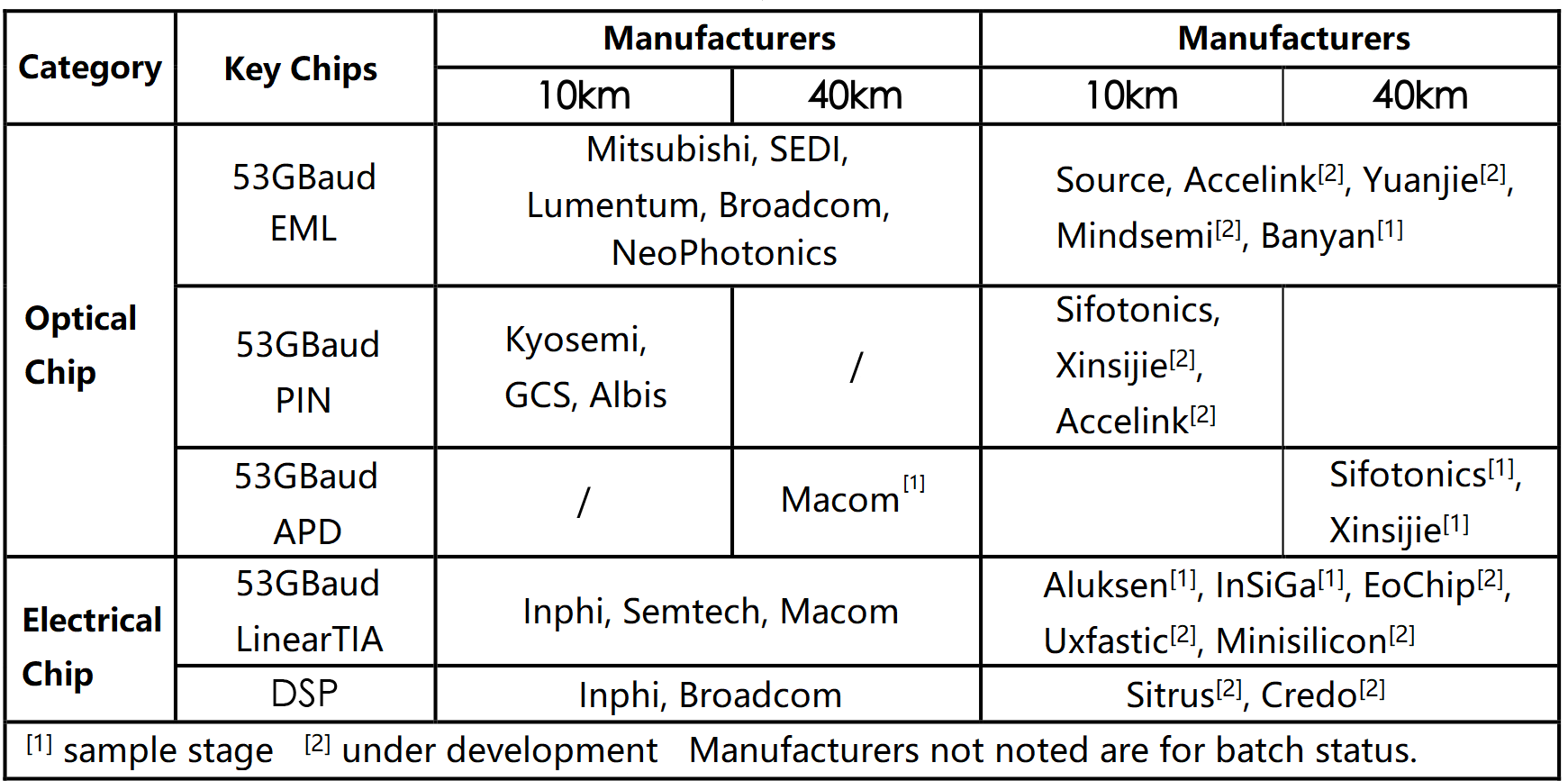
Table 4. The industry chain of 100G QSP28 BiDi optical module chip devices
At present, FiberMall has the ability to supply single-wave 100G BiDi 10km optical modules in bulk. With the increasing maturity of 53GBaud device packaging technology, the product yield of optical modules is gradually improving. The cost of 100G QSFP28 BiDi optical module is expected to be better than 100G QSFP28 LR4 solution, considering the cost of combined splitter and filter, cost of CDR and DSP, number of lasers and wavelength range requirements, packaging cost and production yield. 100G QSFP28 BiDi 10km and 20km optical modules are in the commercial stage. FiberMall’s 100G QSFP28 BiDi 30km optical module has been launched as a sample, and the 100G QSFP28 BiDi 40km optical module is under development and has been verified to achieve 40km transmission in a lab environment.
In the coming years, the demand for 100G QSFP28 BiDi optical modules will be increasingly prominent as the requirements for high precision synchronization, fiber resource-saving and operating cost reduction are further enhanced. FiberMall’s 100G QSFP28 LWMD4 BiDi 20km optical module has been commercially available in small quantities, but the cost is very high because it uses 4 pairs of optical devices; the application of 100G Single Lambda BiDi QSFP28 optical module is also starting to occupy an important position in the blueprint of carrier deployment and equipment vendor integration and is expected to be commercialized in the first half of 2023. The 100G Single Lambda BiDi QSFP28 optical module will potentially have more application space if it can support both Ethernet and OTN signals, but there is no single-wave 100G DSP chip that supports OTN services in the industry, and the related applications and indicators need to be further studied.
100G QSFP28 Optical Module for Distances Above 80km
Application scenarios of 100G optical module with transmission distance above 80km
Point-to-point application scenario:
Point-to-point application scenarios mainly apply to data center access and bearer services are pulled up to the aggregation layer through optical fibers. For example, IP RAN, PTN, and OLT interfaces are connected to bearer networks. As shown in Figure 3 (a), the transmission distance of point-to-point gray light application scenario is usually 40km, 80km or 120km, of which 40km takes the highest proportion and 80km takes the second. Although the demand for 120km is not obvious at present, it has potential possibilities in the future. The traditional 4x25G 100G optical module starts to move from 10km/40km to 80km/120km. As shown in Figure 3 (b), the application scenario of point-to-point colored light is applicable to the situation of fiber resource shortage, and wavelength division multiplexing technology is used to improve fiber utilization.
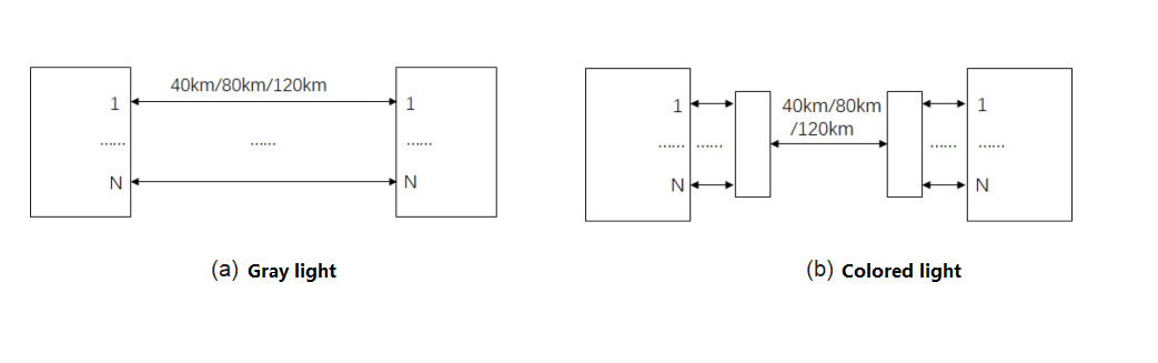
Figure 3. Point-to-point application scenario
Integrated access layer bearer ring application scenarios
The comprehensive access bearer ring mainly has two application requirements. First, the development of comprehensive access services and the new bearer requirements. The transmission bearer services cover 10G, 25G to 100G service access, that is, the bearer rate is increased to 100G. Second, the online transformation of the existing business and the optical fiber restriction of the urbanization pipeline, so as to facilitate the reconstruction of the old foundation and the upgrading of docking requirements, the WDM technology is introduced immediately. To sum up, the transmission distance of 100G QSFP28 optical module is extended to 100km~150km by the low-cost integrated access bearing ring, which means that the traditional metropolitan bearing ring with a transmission distance of 320km is applied to the access bearing ring with a transmission distance of less than 200km.
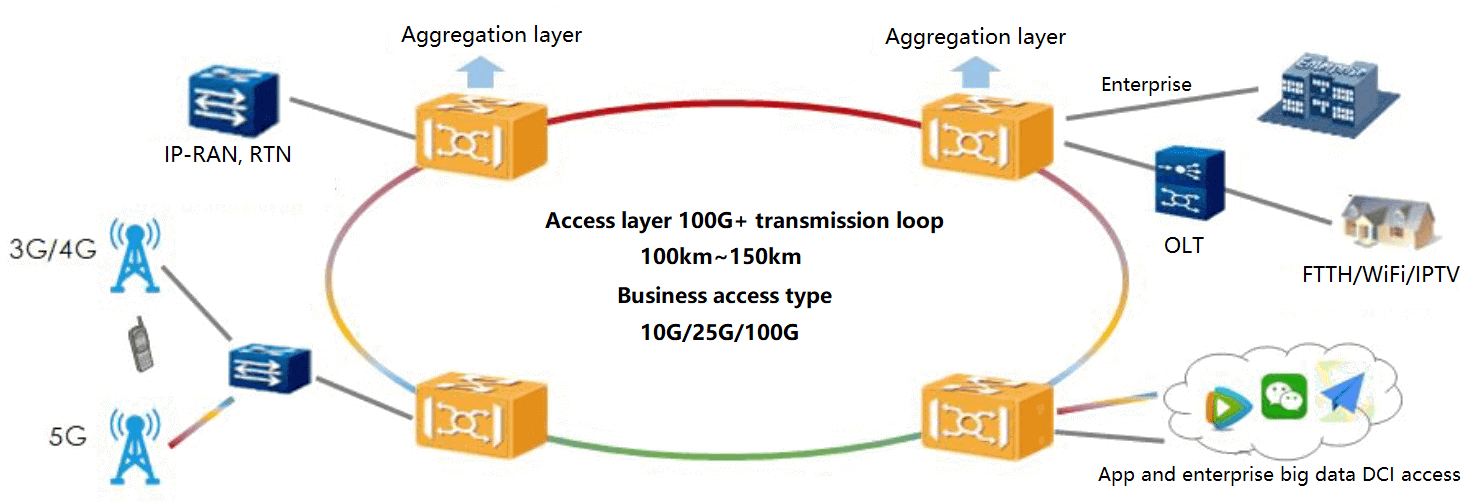
Figure 4. Application scenario of integrated access layer bearer ring
Two types of 100G QSFP28 optical module technology solutions for transmission distances above 80km
100G LWDM4 solution
The gray light solution for transmission distance above 80km can be extended with 100G QSFP28 ZR4 scheme, using 4x25G NRZ modulation code type based on LWDM wavelength. The electrical interface follows the CAUI-4 standard, and the optical interface uses EML laser at the transmitter side and semiconductor optical amplifier (SOA) + PIN detector at the receiver side. The transceiver devices are all hermetically sealed with BOX to effectively guarantee the reliability of the optical module. In order to meet the link budget of more than 80km transmission distance, the technical specifications of the transmitter and receiver are more stringent. Among them, the transmitter side needs to significantly increase the output optical power. Due to the use of EML lasers and the need for all 4 channels to meet the requirements, the yield will be affected to a certain extent. In order to enhance the luminous power, the laser current needs to be increased, which may lead to the working current into the saturation zone, the laser chip luminous efficiency, device coupling process and module hair-end parameters debugging and other new challenges. At the same time, the receiver sensitivity requirements are tightened and the process needs to be further optimized. In addition, the increased current will lead to increased heat generation. The TEC power consumption increases at high temperatures, and the TEC cooling efficiency needs to be optimized to take into account the power consumption requirements of the optical module.
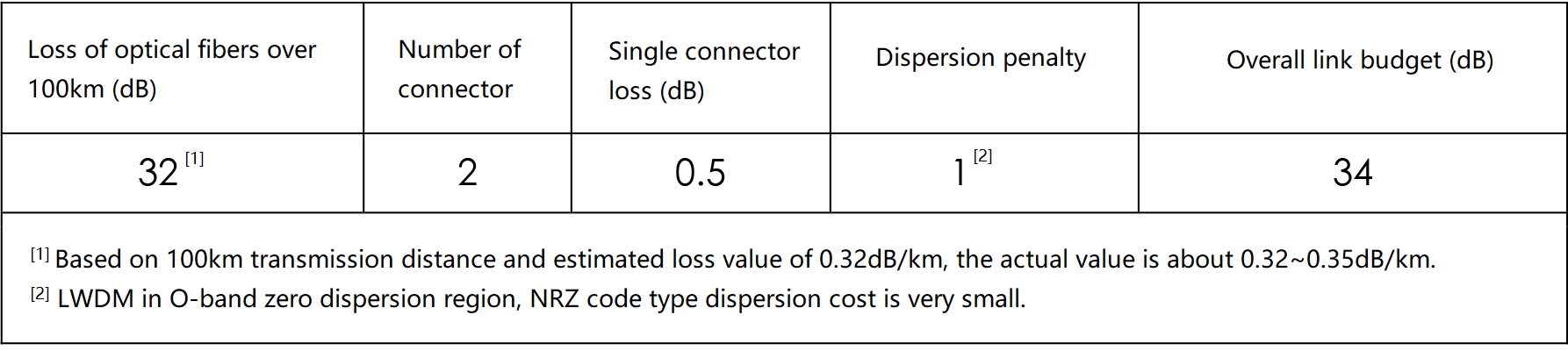
Table 5. Link budget evaluation
100G DWDM solution
DWDM scheme can be subdivided into two kinds of 2x50G dual-carrier DWDM PAM4 technology scheme, Colour A and Colour Z. Colour A scheme: the optical module adopts silicon optical device and PAM4 code type, with external EDFA. It can realize the transmission distance of more than 80km for a single module with dual-carrier 100G rate, and the transmission distance can reach about 150km with two-stage EDFA. The optical module uses QSFP28 package and duplex CS interface with integrated high coding gain SFEC (4E-3 Pre-BER), TOSA with cooled EML at 2×27.5GBaud, and ROSA with 2×27.5GBaud PIN.
The difference between Color Z and Color A is that the laser is DFB and the optical interface is WDM and demultiplexed. The filter bandwidth and dispersion compensation need to be optimized, and the output power, sensitivity and signal-to-noise ratio are significantly reduced compared with Color A. The transmission distance can be up to 120km with two EDFA stages.
(a) Color A solution
(b) Color Z solution
Figure 5. 100G DWDM QSFP28 optical module functional block diagram
In terms of standardization, IEEE802.3ct has specified 100GBASE-ZR based on DP-DQPSK code type and coherent detection. CCSA has discussed the “100G QSFP28 Optical Transceiver Module Part 6: 4×25G ZR4” industry standard project plan, when using 100G QSFP28 ZR4 to support OTN signal transmission, ITU-T technical standard for OTU4 can be used as a reference. At present, there is no industry standard for 100G intensity modulated optical modules with a distance of 80km or more.
FiberMall’s SOA+PIN-based LWDM4 wavelength optical modules for distances over 80km have been in mass production since Q4 2022. The 100G DWDM QSFP28 optical module with a distance of more than 80km based on the dual-carrier 50G solution has been shipped in small quantities. The core optoelectronic chip, SOA + PIN program can share the 100G ZR4 industry chain, optoelectronic chip optional resources are rich, flexible, and diverse combinations of programs, with scale effect and cost advantages.
100G O-band WDM QSFP28 Optical Module
100G O-band WDM system with O-band IM/DD colored optical module as the core, with external WDM/demultiplexer and optical amplifier. With the advantages of low dispersion, low power consumption, and low cost, it supports G.652D and G.652B fiber and can meet the demand of large bandwidth transmission for backhaul access and convergence in 5G applications. It is conducive to promoting further sinking of the WDM system, reducing equipment investment and power consumption, and saving fiber optic cable resources.
In order to be compatible with existing network equipment, the optical module can be packaged with QSFP28, the electrical interface is 4x25G NRZ, and the optical interface has four carriers
(4x25G), dual carrier (2x50G) and single carrier (1x100G) three solutions:
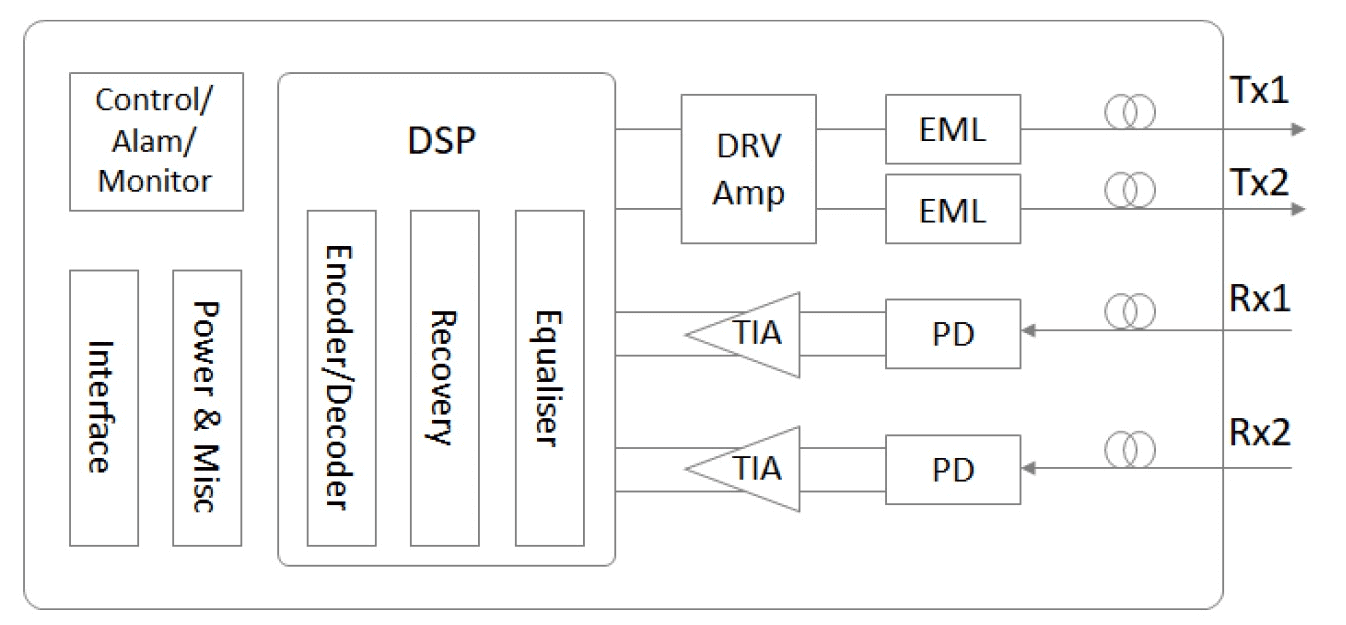
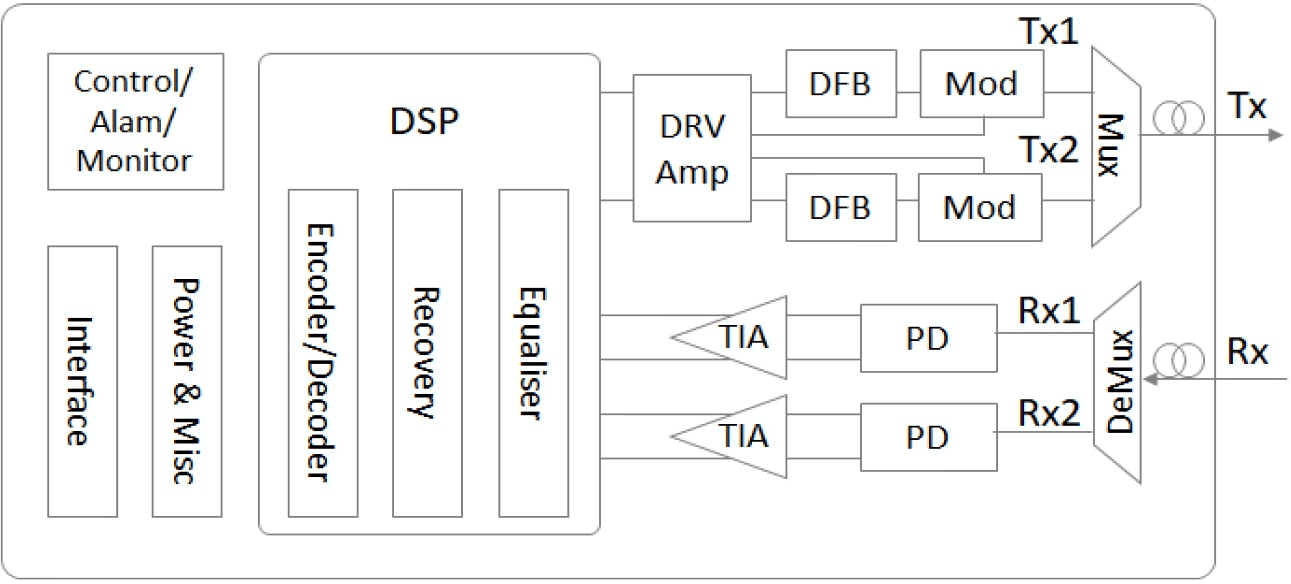
- Four-carrier (4x25G) solution: connected with external WDM/demultiplexer and optical amplifier through MPO interface, using NRZ code type, which can be multiplexed with 25G optical module chain, and the localization rate of the whole system is high. Experimental results of equivalent 4-channel x100G As shown in Figure 6 and Figure 7, the optimization is expected to achieve equivalent 30-channel x100G transmission bandwidth and 80km transmission distance.
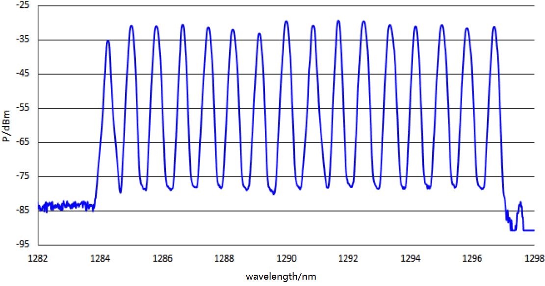
Figure 6. Spectrum diagram of the receiver side of the 4-channel amplifier
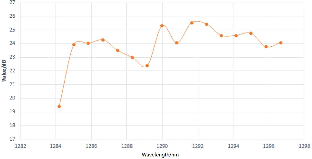
Figure 7. OSNR at the receiver end of the 4-channel wave decomposition multiplexer
Dual-carrier (2x50G) solution: The dual-channel CS interface is connected to an external WDM/demultiplexer and optical amplifier, which can achieve a larger transmission bandwidth relative to the four-carrier solution. The modulation code type has two options, PAM4 and NRZ, and the PAM4 solution can be multiplexed with the 50G optical module chain. Due to the limitation of the signal-to-noise ratio, it can only meet the 40km transmission demand at present, and the 80km transmission technology solution needs to be further verified. NRZ solution has the advantage of signal-to-noise ratio and can more easily meet the 80km transmission demand, but how the existing 56GBaud electric chip can realize 2x25G NRZ to 1x50G NRZ codec processing needs to be researched and needs to be further promoted by electric chip manufacturers in collaboration. Some of the experimental data are shown in Figure 8.
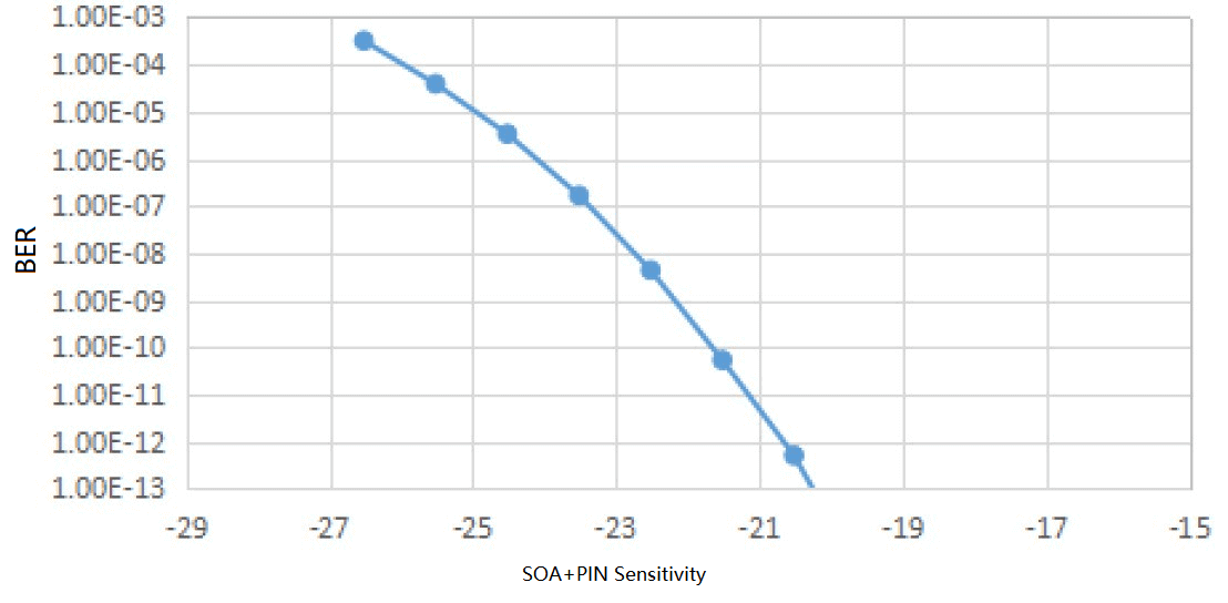
Figure 8. 50G NRZ solution experimental data
(3) single carrier (1x100G) solution: higher transmission bandwidth can be achieved, modulation code type also has PAM4 and NRZ two options. pam4 program can only meet the 40km transmission needs and can be multiplexed 56GBaud electric chip industry chain. 80km technology program needs further research. NRZ solution is more expected to meet the 80km transmission demand, but 112GBaud electric chip to achieve 4x25G NRZ to 1x100G NRZ codec processing solution needs to be promoted in collaboration with the industry chain.
In terms of optical chips, the four-carrier solution is the most mature technology. Dual-carrier and single-carrier solutions require the use of indium phosphide material-based wavelength division multiplexing high-power DC light source and lithium niobate film modulator. Dense WDM DC high-power light source has both high stability, high output, and high wavelength accuracy characteristics. The thin film lithium niobate modulator has high bandwidth, low loss, high extinction ratio, and low chirp characteristics. Therefore, the InP WDM CW LD + TFLN MZ scheme combines high incoming power, high bandwidth, low dispersion cost, and high extinction ratio at the same time. The TOSA structure with TFLN MZ and the principle of the dual-carrier scheme is shown in Figure 9 and Figure 10.
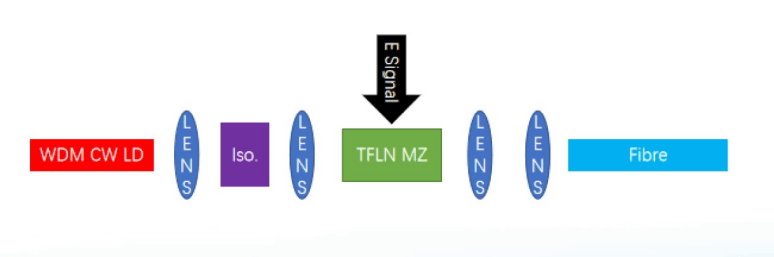
Figure 9. Schematic diagram of TOSA structure using TFLN MZ
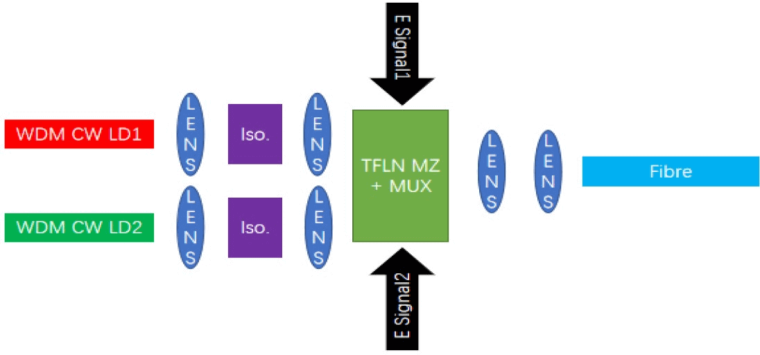
Figure 10. Schematic diagram of the dual-carrier solution
All the above three solutions can achieve wavelength tunable, reducing the variety of optical modules, which is conducive to the simplification of engineering applications.
In terms of product development, FiberMall has launched samples of the quad-carrier solution in Q4 2022. The dual-carrier solution is under development and samples are expected to be available by Q3 2023. The single-carrier solution is in the pre-research stage. In terms of standardization, there are no international or industry standards. However, in the China Communications Standards Association (CCSA TC6WG4) and NGOF (CCSA TC618) related working groups, research projects related to O-band optical modules are underway, and the progress of standardization and industry chain maturity need to be promoted by all parties in the industry.
100G QSFP28 PAM4 Anti-Reflection Technology Research
Anti-reflection technology is one of the important factors to be considered for high-performance and high-reliability links. The PAM4 modulated code has 4 levels and its minimum signal 1 level is about 1/3 of the NRZ code 1 level when its optical modulation amplitude is consistent with that of the NRZ code. When the noise of PAM4 is the same as that of NRZ, the signal-to-noise ratio of PAM4 is about 5dB worse than that of NRZ. Therefore, PAM4 has a lower MPI tolerance than NRZ, and reducing MPI is essential to ensure the transmission performance of PAM4 signals.
The test block diagram of MPI is shown in Figure 11. The transmitted optical signal is divided into two ways, one way contains the optical attenuator for adjusting the optical power to a suitable strength for reception, and the other way uses a polarizer and optical attenuator (or long-distance fiber) to simulate the generation of Rayleigh backward scattering, and the transmitted optical power needs to be high enough to compensate for the insertion loss of the device. The optical power of both signals is adjustable and can be measured by an optical power meter. The sensitivity curves of the two signals can be scanned separately to obtain the corresponding sensitivity curves (the horizontal axis is the incoming power, the vertical axis is the BER), and the difference in sensitivity under the same incoming power conditions is the impact of the MPI cost.
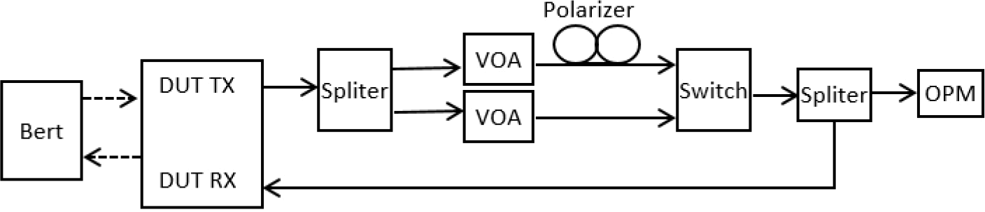
Figure 11. Block diagram of MPI test
The following MPI optimization solutions are currently being investigated in the industry.
(1) Optimization of laser linewidth
The effect of laser linewidth on the MPI of PAM8 optical signal has been simulated earlier in IEEE 802.3. As shown in Figure 12, the link cost for different laser linewidths and connector reflections is verified for a 500m transmission distance containing six connectors, each with the same reflection coefficient. The data show that the narrower the laser line width, the lower the requirement for the connector reflection coefficient at the same link cost. Therefore, the MPI cost can be reduced by optimizing the laser line width.
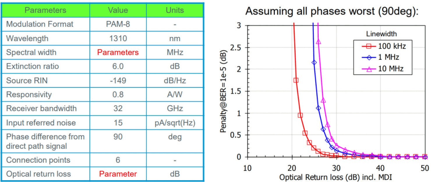
Figure 12. Analysis of the effect of laser linewidth on MPI cost
(2) Compensation by DSP
MPI belongs to linear damage, and the phase of the reflected signal changes compared with the original signal. The total received signal amplitude depends on the phase difference between the original signal and the reflected signal. The smaller the phase difference, the larger the amplitude of the received total signal, as shown in Figure 18. Based on this principle, the MPI can be compensated by DSP algorithms. At present, leading DSP vendor Marvell has launched DSP with MPI compensation function, and a few optical module vendors have developed optical modules with MPI compensation function. However, the overall research is still in the early stage, and the actual application of engineering effect needs to be further verified. The maturity of the industry chain needs to be further promoted by relevant parties in the industry.
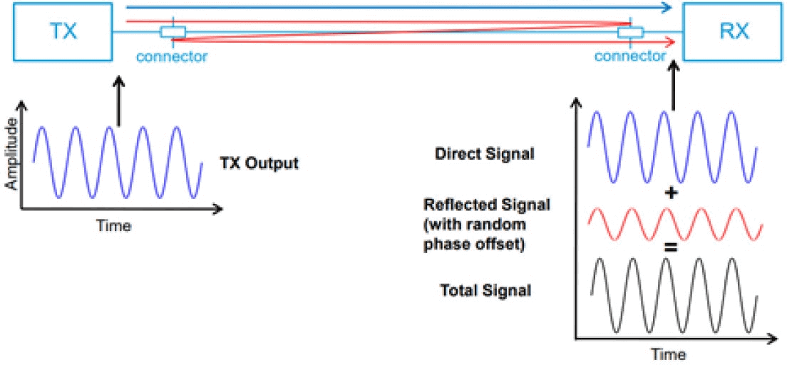
Figure 13. MPI principle diagram
(3) Optimization of fiber optic links
In addition, MPI can also be reduced by selecting better quality fiber, effectively cleaning the connector end face, reducing the reflection caused by an air gap or small particles in the connector, and attention to alignment errors in the connector. Such as the use of fiber end face 8 ° beveled APC connector, so that the reflected light is reflected at an angle into the cladding, rather than directly reflected into the light source to increase return loss, can reduce the impact of MPI.
FiberMall Optical Module Productization Level
FiberMall is actively developing optical modules to meet the needs of 5G bearer applications. Based on the previous white paper research, Table 6 summarizes the productization capacity of 5G bearer optical modules of FiberMall at present.
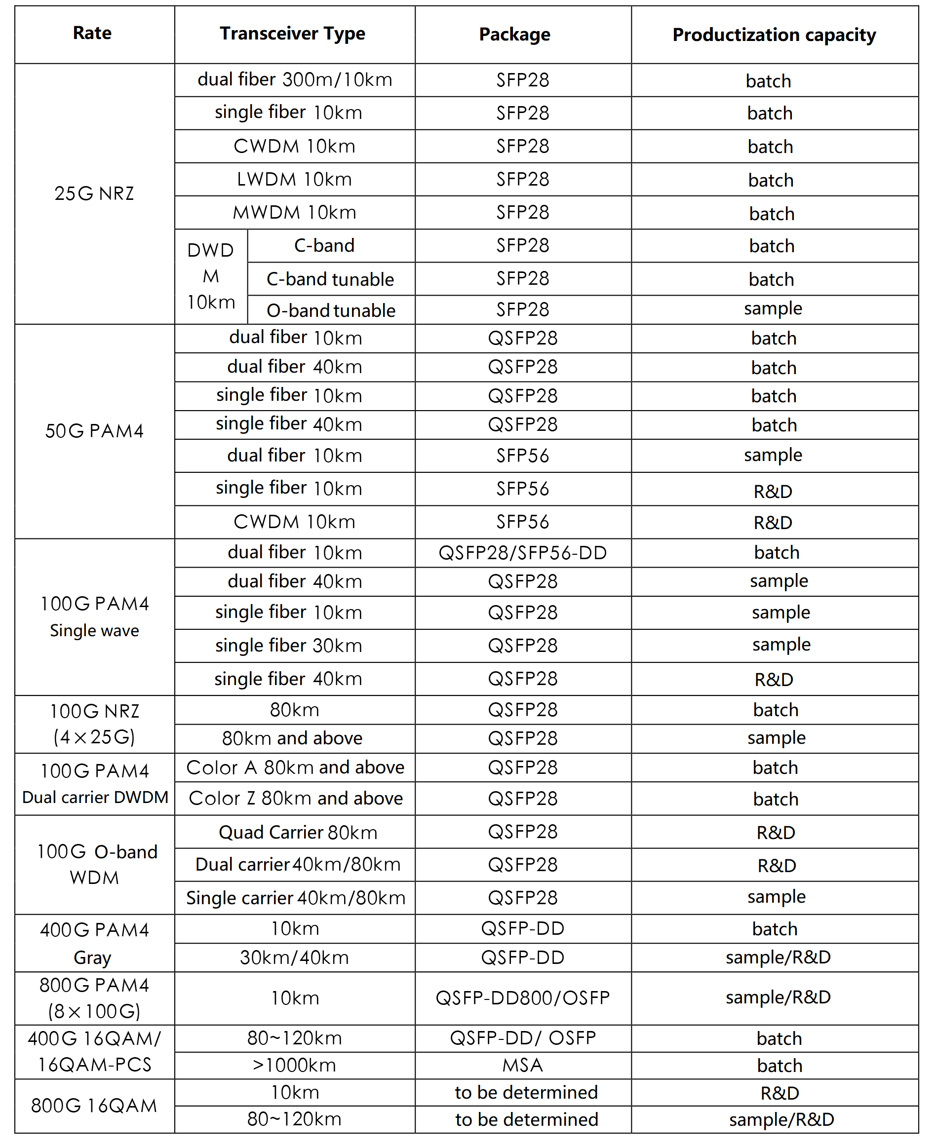
Table 6. FiberMall’s 5G bearer optical module productization capability
FiberMall’s Productization Level of Optoelectronic Chip Devices
The overall productization capability of FiberMall for the core optoelectronic chip devices used in optical modules is shown in Table 7.
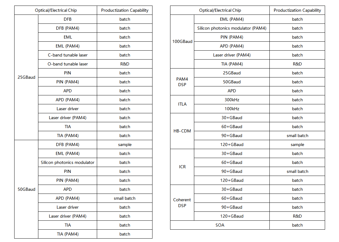
Table 7. Productization capability of the core optoelectronic chip
Optical modules play an important role in ensuring the transmission performance of mobile communication networks. With the continuous advancement of 5G construction and the continuous enrichment of application scenarios, in order to meet the carrying requirements of larger bandwidth, higher performance, lower cost, and smaller size, FiberMall is constantly exploring the research on new 5G forward and middle return optical module technology, so as to fully prepare for the deployment of next-generation 5G. In order to effectively solve the current problems and challenges of the new technology solutions, FiberMall needs to bring together the upstream and downstream forces of the industry chain, open discussions, and collaborate on key issues from strengthening technological innovation, guiding market gathering, and strengthening the industrial base.
In terms of technological innovation, FiberMall meets the new demand for optical modules in different application scenarios through technical R&D and innovation of new materials, new designs, new processes, new interfaces, etc. FiberMall promotes the research of next-generation 5G bearer optical module technology from various aspects such as deployment demand, transmission performance, low-cost construction and convenient operation and maintenance management, benign development of the industry chain, orderly allocate resources and achieve cost reduction through scale effect.
FiberMall needs to further strengthen the supporting capabilities of industrial bases such as high-precision manufacturing process platforms, process materials, equipment, and meters, so as to reduce the R&D cost and shorten the R&D cycle, so as to break through the core and key technologies. FiberMall needs to further improve its evaluation mechanism and effectively evaluate the feasibility, reliability, interoperability, and compatibility of various optical modules and optoelectronic chip devices through an open test and verification platform, so as to guide the industry to develop key technologies and improve product performance.
FiberMall is willing to strengthen cooperation and gather consensus with the industry to promote the research, testing, and evaluation of key technologies of next-generation 5G bearer optical modules, as well as the formulation of standards and specifications, so as to promote the healthy and orderly development of 5G bearer optical module technology industry.
Related Products:
-
 QSFP28-100G-PSM4 100G QSFP28 PSM4 1310nm 500m MTP/MPO SMF DDM Transceiver Module
$180.00
QSFP28-100G-PSM4 100G QSFP28 PSM4 1310nm 500m MTP/MPO SMF DDM Transceiver Module
$180.00
-
QSFP28-100G-LR4 100G QSFP28 LR4 1310nm (LAN WDM) 10km LC SMF DDM Transceiver Module
$285.00
-
QSFP28-100G-IR4 100G QSFP28 IR4 1310nm (CWDM4) 2km LC SMF DDM Transceiver Module
$110.00
-
QSFP28-100G-ZR4+ 100G QSFP28 ZR4+ LWDM4 100km LC SMF DDM Optical Transceiver Module
$2000.00
-
QSFP28-100G-LR4-20 100G QSFP28 LR4 1310nm LWDM4 20km LC SMF DDM Transceiver Module
$300.00
-
Q28-2DW1314-80C 100G DWDM QSFP28 PAM4 80km C13 C14 100GHz CS DDM Optical Transceiver
$1600.00
-
Q28-DW100G15-80C Compatible 100G DWDM QSFP28 PAM4 Single Wave C15 1565.50nm 100GHz LC 80km DDM Optical Transceiver Module
$1900.00
-
QSFP28-100G-FR1-C27 100G CWDM QSFP28 Single Lambda FR 1271nm 2km LC SMF with FEC DDM Optical Transceiver
$500.00
-
QSFP28-100G-LR1-C27 100G CWDM QSFP28 Single Lambda LR 1271nm 10km LC SMF with FEC DDM Optical Transceiver
$600.00
-
Q28-100G32-BX20 100G QSFP28 BIDI TX1311nm/RX1291nm Single Lambda LC SMF 20km PAM4 DDM Optical Transceiver Module
$600.00
-
Q28-100G94-BX30 100G QSFP28 BIDI TX1309nm/RX1304nm Single Lambda LC SMF 30km PAM4 DDM Optical Transceiver Module
$1100.00
-
Q28-100G49-BX40 100G QSFP28 BIDI TX1304nm/RX1309nm Single Lambda LC SMF 40km PAM4 DDM Optical Transceiver Module
$1200.00
-
Q28-100G32-BX10 100G QSFP28 BIDI TX1331nm/RX1271nm PAM4 Single Lambda LC SMF 10km DDM Optical Transceiver Module
$500.00
-
Q28-100G23-BX20 100G QSFP28 BIDI TX1291nm/RX1311nm Single Lambda LC SMF 20km PAM4 DDM Optical Transceiver Module
$600.00