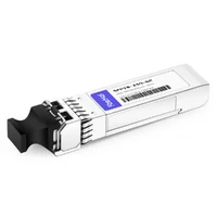
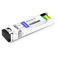
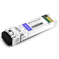
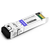
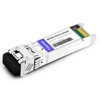
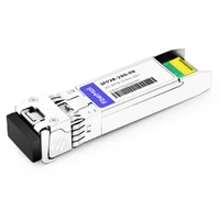
At 9:40 a.m., Elena plugged a new 25G SFP28 optical transceiver into a row switch and waited for the link light. Nothing happened. The module fit perfectly, the fiber jumpers were clean, and the product label looked right. But the port was configured for 10G, while the switch model did not support 25G on that cage.
That is the real SFP28 compatibility problem. Mechanical fit is only the first check. A working 25G link depends on the host port, configured speed, firmware and coding policy, media type, FEC settings, power budget, and the device at the far end. This guide gives you a practical way to verify each item before ordering optics or cables for a deployment.
Start with the complete 10G and 25G comparison in our SFP28 vs. SFP+ transceiver guide. Then use the process below to qualify a specific switch, router, or NIC link.
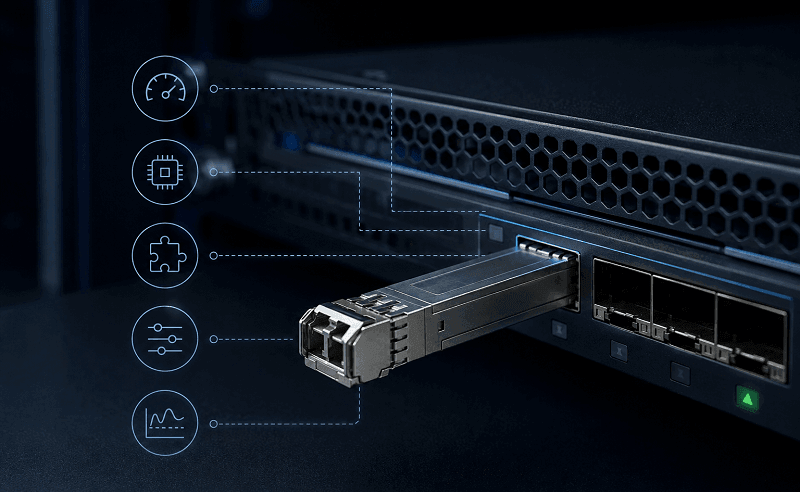
What Determines SFP28 Compatibility?
SFP28 compatibility means that both endpoint ports, the installed optics or cable, and the physical link support the same 25G operating mode. The modules may share a cage with SFP+ products, but speed capability, vendor qualification, firmware, FEC, connector type, fiber, and optical budget still have to match.
SFP28 is a single-lane form factor used commonly for 25 Gigabit Ethernet. Its host signaling operates at 25.78125 GBd with 64b/66b coding under the relevant Ethernet specifications. That is far beyond a 10G-only port’s signaling capability, even if the cage looks identical. See IEEE 802.3 for the standards context.
Think of the cage as a parking space, not a guarantee that every vehicle can operate there. The cage establishes physical dimensions. The host hardware and its software decide which line rates, module identifiers, power classes, and link modes it will accept.
A clean SFP28 compatibility review checks these seven areas before purchase:
- Host capability: Exact switch, router, or NIC model; port type; ASIC or PHY capability; and installed network operating system or driver.
- Port mode: Intended speed, channelization, breakout state, autonegotiation behavior, and any port-group limits.
- Vendor qualification: The platform vendor’s current supported-optics documentation and the module supplier’s coding statement.
- Media design: PMD, wavelength, connector, fiber grade, number of fibers, cable length, and link loss.
- Endpoint alignment: Compatible optics or cable assemblies at both ends, rather than just matching form factors.
- Link settings: FEC, speed configuration, and other PHY settings that must agree across the connection.
- Thermal and operational fit: Module power class, airflow, ambient temperature, DOM/DDM telemetry, and error-counter stability.
That list may seem detailed. It is still much shorter than troubleshooting a link after 48 racks are already cabled.
Planning a 25G refresh? Review the optical transceiver basics first, then record the exact host and port data for each link class in your design.
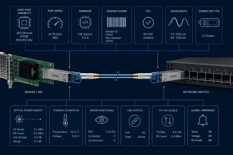
SFP28 Port Compatibility Starts With the Host
Identify the exact port capability
Do not begin with the module SKU. Begin with the port. A switch can contain SFP-shaped cages that run only 1G or 10G, while another platform may support 10G and 25G on the same physical cage. Port support may also differ between line cards, switch families, and even port groups on the same chassis.
Record the full device model, hardware revision if relevant, port number, and operating system release. Then find the vendor’s current hardware compatibility list or transceiver matrix for that exact platform. A generic product-family statement is not enough for a production order.
Consider a typical data-center refresh. Omar’s team had 24 dual-port server NICs that supported 10G and 25G, plus a leaf switch with mixed-capability SFP cages. The team assumed all 48 uplinks could move to 25G. A port map showed that only 32 cages supported the desired 25G mode, so they changed the bill of materials before the optics order went out.
That small check avoided a rack-by-rack replacement later. This is an illustrative deployment scenario, but the decision process applies to any mixed-speed switch.
Confirm the port mode and software state
A 25G-capable port may still need a supported speed setting or a current software release before it can establish the intended link. The same is true for a NIC driver. Document the configured speed, FEC state, and any breakout or channelization choice on both endpoints.
Do not assume that a port will negotiate from 10G to 25G on its own. Ethernet behavior varies by platform and interface. Use the vendor’s documentation for the selected hardware, then test the exact configuration in a representative environment.
Build a pre-purchase compatibility record
Create one record for each unique link design. It can be a simple spreadsheet or change-control entry, but it should contain enough data for another engineer to reproduce the result.
| Field | What to record | Why it matters |
| Host endpoint | Exact device and port | Determines physical and electrical support |
| Software | NOS, firmware, or driver release | Can change supported module behavior |
| Port configuration | 10G or 25G mode, FEC, breakout state | Must align with the endpoint and media |
| Optic or cable | Supplier SKU and coding target | Identifies the component under test |
| Media | PMD, fiber grade, connector, length | Determines reach and signal path |
| Far endpoint | Device, port, module, and settings | A link is only as compatible as both ends |
| Test result | Link status, DOM/DDM, and error counters | Turns a purchase assumption into a validated design |
This record is especially useful when a data center runs more than one switch vendor. A module that passes in one device family can still need different coding or qualification in another.
Can SFP28 Work in an SFP+ Port?
The short answer is usually no for a 25G link unless the host port explicitly supports 25G operation. An SFP28 optical transceiver can physically fit in many SFP+ cages. Physical fit does not give a 10G-only host the electrical capability to run a 25G signal.
The reverse direction is also conditional. Some SFP28-capable ports can run a 10G SFP+ module after the correct speed and platform configuration are applied. Others cannot, or support it only on specific ports and software versions. Confirm the exact port’s supported speed modes instead of relying on the form factor name.
| Installation direction | Physical fit | Likely result | What to verify |
| 25G SFP28 module in a 10G-only SFP+ port | Often fits | 25G link will not establish | Host port line-rate support and supported optics list |
| 25G SFP28 module in a 10/25G SFP28 port | Fits | May work after full validation | Port mode, coding, FEC, media, and firmware |
| 10G SFP+ module in a 10/25G SFP28 port | Often fits | Platform-dependent | Supported 10G mode, software release, and module qualification |
| 25G DAC or AOC in a 10G-only port | Connector may fit | 25G link will not establish | Host support, cable coding, and validated cable length |
The label “SFP28” describes a form-factor and electrical family. It does not mean every SFP-shaped port accepts every module in that family. The same caution applies to cables. A passive or active 25G cable assembly still needs compatible host ports and a validated length.
The underlying port architecture also matters when comparing SFP and quad-lane interfaces. Our guide to SFP and QSFP switch ports explains why single-lane 25G server links and 100G uplinks require different interface planning.
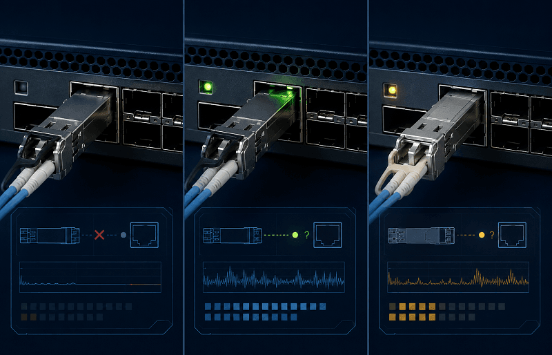
Verify Vendor Coding, Firmware, and Approved Optics
MSA compliance is a starting point
Multi-Source Agreement specifications define key mechanical, electrical, and management conventions for optical modules. That consistency makes third-party interoperability possible. It does not require every network platform to accept every vendor-coded module.
A host device can read module identification information over its management interface and apply its own policy. The device may accept the module, warn about unsupported optics, limit diagnostics, or reject the component. Firmware and operating-system updates can change that behavior, so a test result from an older release is not a permanent compatibility certificate.
The SNIA SFF specification library documents the SFF specifications used for module form factors and management interfaces. Those specifications help define the common interface. Your switch, router, or NIC vendor still controls the support policy for its own platform.
Validate each vendor platform responsibly
Cisco, Arista, Juniper, Dell, HPE, NVIDIA, and other vendors publish hardware and optics guidance for their platforms. Treat that guidance as a per-model, per-release check. Do not turn it into a blanket statement such as “all Cisco switches support this optic.”
A useful vendor validation matrix looks like this:
| Platform field | Validation question |
| Device family and model | Does this exact platform expose 25G on the selected port? |
| Software or driver release | Does the current release list the intended optic or cable behavior? |
| Supported-optics source | What is the current official matrix or hardware guide? |
| Coding requirement | Does the supplier specify a coding target for this platform? |
| Port configuration | Are 25G speed and FEC settings supported and enabled? |
| Test status | Has this module, cable, and software combination passed an end-to-end test? |
Here is a second illustrative scenario. Lina manages a small colocation footprint with leaf switches from two vendors.
Her team used the same 25GBASE-SR optical specification on both fabrics, but they did not reuse the same validation record. They checked coding and software independently, tested one link per platform, and stored the approved module SKU with the switch model. That left them with a clean ordering rule instead of a vague claim that the optics were “multi-vendor compatible.”
Protect the production change window
Compatibility is not just a procurement task. It is part of change control. Before a large deployment, retain the module data sheet, host documentation, coding request, and test results. If a later software upgrade changes module behavior, those records help the network team compare the old and new states quickly.
Avoid unapproved commands intended to bypass a platform’s optics policy. They can change support status, complicate troubleshooting, and create inconsistent behavior between sites. Use the equipment vendor’s supported process and FiberMall’s compatibility guidance for the specific switch or NIC you plan to deploy.
Match Optics, Cables, and Fiber at Both Ends
A host can accept a module and still fail to build a clean link. The two ends also need compatible media, reach, and configuration. For removable optics, match the Ethernet PMD, wavelength family, connector, fiber type, and supported distance. For DAC and AOC assemblies, match the exact cable type, rate, length, and host support.
Select the right 25G optical medium
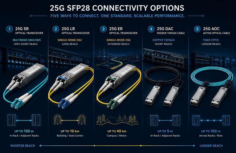
For standards-based 25G links, the physical media choice is usually driven by the installed fiber plant and required reach. The Cisco 25GBASE SFP28 Modules Data Sheet lists the commonly referenced values below.
| Link type | Typical media | Reference reach | Compatibility check |
| 25GBASE-SR | OM3 or OM4 multimode fiber | Up to 70 m on OM3; up to 100 m on OM4 | Verify fiber grade, duplex polarity, LC connectors, and total channel length |
| 25GBASE-LR | Single-mode fiber | Up to 10 km | Check 1310 nm optics, duplex SMF, and optical loss budget |
| 25GBASE-ER | Single-mode fiber | Up to 40 km | Check platform support, optical budget, and the exact module specification |
| Passive or active DAC | Twinax cable assembly | Product- and host-dependent | Check rate, coding, approved length, bend path, and power draw |
| AOC | Integrated active optical assembly | Product- and host-dependent | Check rate, coding, validated length, and cable routing requirements |
The reach figures above are reference limits, not a promise that every installed channel will work at that distance. Patch panels, connectors, splices, contamination, bend loss, and the actual transmitter and receiver specifications all affect margin.
For example, a 25GBASE-SR link that crosses 82 m of OM4 fiber may look safe against the 100 m reference. But three patch fields and poorly cleaned connectors can still reduce the available margin. Inspect the end faces, confirm polarity, and review receive optical power after link-up. Small physical issues become expensive at 25G.
Pair wavelengths and connector topology correctly
Two duplex SR or LR modules of the same supported PMD can form a normal point-to-point link when the fiber plant and port settings match. BiDi modules work differently. They use complementary transmit and receive wavelengths over one single-mode strand, so the two ends must use the intended pair, not two identical units.
WDM optics require a second layer of validation. The module wavelength or channel plan must match the mux or demux passband, and the link budget must include insertion loss from the transport components. These are engineering checks, not catalog filters.
Treat DAC and AOC as part of the host design
DAC and AOC products simplify short-distance 25G links because the cable and optics are built as one assembly. They do not remove compatibility work. Check the exact product data sheet, host support, coding, length, and the path through the rack.
For same-rack server-to-switch connections, a validated DAC can be a cost-effective choice. For rack-to-rack paths with tight weight or cable-management constraints, an AOC may suit the physical route better. FiberMall’s 25G SFP28 optical transceivers and compatible cable assemblies cover the media options, but the final choice still starts with the host and cable path.
Validate SFP28 Compatibility Before Deployment
The best time to find a mismatch is before a purchase order turns into a row of inactive ports. Use a representative test link that matches the production host models, software versions, optics or cable SKUs, fiber path, and intended configuration.
Align FEC and endpoint settings
Forward error correction, or FEC, is a link-level setting that can improve tolerance to signal errors on supported interfaces. It is not a universal feature contained inside every SFP28 optic. The required or supported FEC mode depends on the host PHY, the selected media, and the platform configuration.
Both ends must agree where FEC is used. A mismatch can prevent link establishment or produce errors. Check the switch and NIC documentation for the selected port, then record the tested configuration with the module or cable SKU.
Priya’s team saw this during a 25G server rollout. The optics and fiber matched, but one endpoint retained its previous FEC setting after a maintenance window. The link came up intermittently and accumulated errors under load.
Once the team compared the endpoint settings and retested the pair, the error counters remained stable. That is an illustrative example, yet FEC alignment is a common item to include in a validation plan.
Use a five-step acceptance test
- Confirm the host: Verify the exact device model, port capability, software release, and approved-optics documentation.
- Confirm the link design: Match PMD or cable type, speed, wavelength, connector, fiber grade, topology, and calculated channel loss.
- Align configuration: Set the intended rate, FEC, and any supported port-mode options at both endpoints.
- Inspect the physical path: Clean and inspect fiber connectors, verify polarity, avoid excessive bend stress, and confirm the correct cable length.
- Observe the live link: Check link state, DOM/DDM telemetry where available, receive power, alarms, and error counters over a meaningful test period.
DOM or digital optical monitoring exposes useful operating data such as temperature, voltage, transmit power, receive power, and laser bias on supported optical modules. Use it as evidence, not as a substitute for the host’s support matrix. A link can show valid optical levels while the platform still flags a qualification or configuration issue.

Answer common SFP28 compatibility questions
Do all 25G SFP28 links need FEC?
No. FEC behavior depends on the host platform, PHY, selected PMD or cable assembly, and configuration. Check the official documentation for both endpoints and test the exact setting you plan to use. Never enable or disable FEC across a production link without understanding the far endpoint.
Why does the same optic work in one device but not another?
The devices may have different port line-rate capabilities, supported-optics policies, firmware releases, coding requirements, power limits, or FEC defaults. Compare the two validation records field by field instead of assuming the optic itself has changed.
Can I mix brands at each end of a 25G link?
Often, yes, if both hosts support the chosen PMD or cable assembly and the optics, media, configuration, and vendor policies align. “Often” is not a substitute for a test. Validate the exact two-end combination before deployment.
Build a Reliable 25G Link
SFP28 compatibility is a full-link engineering decision. Start with the host port, confirm its 25G capability and current software, then match optics or cables to the fiber plant and far endpoint. Check vendor qualification and coding policies early.
Align FEC and link settings. Finally, test one complete connection before scaling it.
The practical takeaway is simple:
- Physical fit does not prove 25G support.
- MSA alignment does not override a platform’s optics policy.
- Both ends must match the intended media and link mode.
- SR, LR, ER, DAC, and AOC choices depend on the installed path, not only price.
- A documented pilot link creates a repeatable bill of materials for production.
If you are planning a 10G-to-25G upgrade, use this SFP28 compatibility guide as the pre-purchase checklist. Then explore FiberMall 25G SFP28 options or contact our networking experts with your switch model, software release, port mode, distance, fiber type, and required link count. That information lets the compatibility review focus on a stable, scalable 25G design.
Related Products:
-
 SFP28-25G-SR 25G SFP28 SR 850nm 100m LC MMF DDM Transceiver Module
$25.00
SFP28-25G-SR 25G SFP28 SR 850nm 100m LC MMF DDM Transceiver Module
$25.00
-
SFP28-25G-ESR 25G SFP28 ESR 850nm OM3 200m/OM4 300m LC MMF DDM Transceiver Module
$35.00
-
SFP28-25G32-BX10 25G BX BIDI SFP28 TX1330nm/RX1270nm 10km LC SMF DDM Transceiver Module
$42.00
-
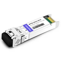
SFP28-25G23-BX10 25G BX BIDI SFP28 TX1270nm/RX1330nm 10km LC SMF DDM Transceiver Module
$42.00
-
SFP28-25G-LR 25G SFP28 LR 1310nm 10km LC SMF DDM Transceiver Module
$45.00
-
SFP28-25G32-BX10I 25G BX BIDI SFP28 TX1330nm/RX1270nm 10km LC SMF DDM Industrial Transceiver Module
$50.00
-
SFP28-25G23-BX10I 25G BX BIDI SFP28 TX1270nm/RX1330nm 10km LC SMF DDM Industrial Transceiver Module
$50.00
-
SFP28-25G32-BX03C 25G BX BIDI SFP28 TX1330nm/RX1270nm 300m LC SMF DDM Transceiver Module
$58.00
-
SFP28-25G23-BX03C 25G BX BIDI SFP28 TX1270nm/RX1330nm 300m LC SMF DDM Transceiver Module
$58.00
-
SFP28-25G-ER 25G SFP28 ER 1310nm 40km LC SMF DDM Transceiver Module
$125.00
-
SFP28-25G32-BX40 25GBASE SFP28 BIDI ER TX1310nm/RX1270nm 40km LC SMF DDM Optical Transceiver Module
$180.00
-
SFP28-25G23-BX40 25GBASE SFP28 BIDI ER TX1270nm/RX1310nm 40km LC SMF DDM Optical Transceiver Module
$180.00