With the rapid development of cloud computing, big data, ultra-high-definition video, artificial intelligence, and 5G industry applications, the frequency of network access and access methods continue to increase, and network data traffic grows rapidly, posing higher challenges to data center interconnection (DCI). Taking a data center with a spine-leaf CLOS architecture as an example, the typical optical interconnection scenarios are shown in Table 1. The first three scenarios are interconnection within the data center, and the fourth scenario is the interconnection among data centers.
| Interconnection Scenarios | Typical Distance | Typical Requirements for Optical Modules | ||||
|---|---|---|---|---|---|---|
| Last Generation | At Present | Next Generation | ||||
| Scenario 1 | Server to TOR (within Data Center ) | 2m(within the rack) 30/50m(across racks) | within Machine Room | 25G AOC/DOC | 100G AOC/DAC | 200G AOC/DAC |
| Scenario 2 | TOR to Leaf (within Data Center) | ≥70m/100m | within Building | 100G SR4 | 400G SR8/SR4.2 | 800G PSM8/PSM4 |
| Scenario 3 | Leaf to Spine (within Data Center) | 500m/2km | among Buildings | 100G CWDM4 | 400G FR4/DR4 | 800G FR4/PSM4 |
| Scenario 4 | Among Data Centers | 80-120m | among Campuses | 100G DWDM | 400G ZR/ZR+ | 800G ZR |
Table1: Typical Optical Interconnection Scenarios of Data Centers
1. Optical Module Requirements for Internal Interconnection of Data Centers
The internal interconnection of the data center accounts for a large proportion of the overall traffic distribution of the data center. The typical requirements for optical modules are shown in Table 1, and there are development trends toward high speed, low power consumption, low cost, intelligence, etc.
(1)The Trend Toward High Speed
The internal interconnection within Amazon, Google, Microsoft, Facebook, and other North American ultra-large data centers has begun commercial deployment of 400Gb/s optical modules between 2019 and 2020. Domestic data centers are gradually transitioning from 100Gb/s to 400Gb/s transceivers, and the scale deployment is expected to be realized in 2022. As shown in Diagram 1, the throughput of data center switching chips are expected to reach 51.2Tb/s in 2023 and 102.4Tb/s after 2025. Higher rates of 800Gb/s and 1.6Tb/s will become important choices to realize high-bandwidth data exchange.
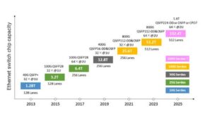
Diagram1: the developing trend of data center switch chip throughput
(2) The Trend Toward Low-consumption
As the capacity of switching chips continues to increase, the power consumption of optical modules has begun to exceed that of switching chips, becoming a key factor in network solutions. The early power consumption of 400Gb/s optical modules is 10~12W, and the long-term power consumption is expected to be 8~10W; the power consumption of 800Gb/s optical modules is about 16W. In addition, the industry expects to reduce the power consumption and cost of interconnecting SerDes by encapsulating the optical engine and the switching chip, and CPO (co-packaged optics) technology encapsulates electronic chips and optical engines together, which has become a research hotspot in the industry.
(3) The Trend Toward Low Cost
There are massive interconnection requirements in data centers, and low cost is one of the main driving forces for the continuous development of optical module technology solutions. First, the access cables in scenario one show a trend of diversification. Some solutions reduce the interconnection distance by adjusting the cabinet layout, and using lower-cost direct-attached copper cables (DAC) instead of optical cables; second, with the stable operating environment and fast replacement of data center optical modules, the industry is actively exploring solutions to lower costs by reducing requirements for temperature and long-term reliability and so on; thirdly, as the speed continues to increase, the sinking trend of coherent solutions is obvious, and non-coherent solutions are also striving to expand to long distances. The two schemes “meet” in some application scenarios, and the proportion of demand for different schemes in the “meeting” scenes will be closely related to factors including cost.
(4)The Trend Toward Intelligence
OTT has begun to pay attention to the enhancement of the operation and maintenance capabilities and quality improvement of optical modules. The health monitoring of optical modules and early warning of faults are realized through artificial intelligence, machine learning, and big data, which puts forward new requirements for the functional characteristics and specifications of optical transceivers.
| Types of Optical Modules | Form Factor | Optical Interface Rate Gb/s | Electrical interface rate Gb/s | Transmission Distance | Number of Fibers | Typical Power Consumption | |
|---|---|---|---|---|---|---|---|
| 100Gb/s | VR | QSFP28 | 100 | 100 | 30/50m | 1 | <3.5W |
| SR4 | 4×25 | 4×25 | 70/100m | 4 | |||
| PSM4 | 4×25 | 4×25 | 500m | 4 | |||
| CWDM4 | 4×25 | 4×25 | 2km | 1 | |||
| LR4 | 4×25 | 4×25 | 10km | 1 | |||
| 200Gb/s | VR2 | QSFP56 | 2×100 | 2×100 | 30/50m | 2 | <6.5W |
| SR4 | 4×50 | 4×50 | 70/100m | 4 | |||
| FR4 | 4×50 | 4×50 | 2km | 1 | |||
| LR4 | 4×50 | 4×50 | 10km | 1 | |||
| 400Gb/s | VR4 | QSFP-DD/OSFP | 4×100 | 4×100 | 30/50m | 4 | <12.0W |
| SR8 | 8×50 | 8×50 | 100m | 8 | |||
| SR4.2 | 8×50 | 8×50 | 100m | 4 | |||
| DR4 | 4×100 | 4×100 | 500m | 4 | |||
| FR4 | 4×100 | 4×100 | 2km | 1 | |||
| LR4 | 4×100 | 4×100 | 10km | 1 | |||
| 800Gb/s | VR8 | QSFP-DD800 /OSFP /QSFP224 /CPO | 8×100 | 8×100 | 30/50m | 8 | 16W |
| PSM8 | 8×100 | 8×100 | 70/100m | 8 | |||
| DR8 | 8×100 | 8×100 | 500m | 8 | |||
| DR4 | 4×200 | 8×100 | 500m | 4 | |||
| 2×FR4 | 8×100 | 8×100 | 2km | 2 | |||
| FR4 | 4×200 | 8×100 | 2km | 1 | |||
Table2: Optical Module Requirements of Internal Data Center Interconnection
2. Optical Modules Used in the Interconnection Among Data Centers
In the early stage, it was mainly accessed through the Internet. With the increase in business traffic, the data traffic reached more than Tb/s, and problems such as network delay, congestion, and security required special interfaces to support. Data centers are energy-intensive industries. Due to the constraints of power supply and the surrounding environment, the scale of a single data center cannot be expanded infinitely. The extensive application of modern virtualization technology enables multiple physically separated data centers to work like a virtual data center, and large Internet companies can share the load among multiple data centers and services, effectively reducing the data center’s demand for power supply, and facilitating rapid deployment. In addition, in consideration of disaster recovery and backup, many large data centers are composed of multiple sites, between which a large number of low-latency data exchange channels are required. The above application scenarios all place strong demands on DCI. The DCI distance is generally several kilometers to tens of kilometers, or even more than 100 kilometers. Typical interconnection scenarios are as follows:
(a) DCI-Campus: Connect to a data center at a short distance. The transmission distance is usually about 2km, and further expands to a longer distance of 10km;
(b) DCI-Edge: Distributed data center in the connection area. The transmission distance is usually 80km~120km;
(c) Metro/Long Haul: It is further extended to the metropolitan area and long-distance transmission, and the distance can reach hundreds or thousands of kilometers. In order to make full use of optical fiber resources, dense wavelength division multiplexing (DWDM) technology is widely used, and different modulation codes can be used for different transmission distances. In addition, although not part of the DCI infrastructure, wireless networking is also being integrated into the data center network.
For DCI within 20km, depending on the connection bandwidth and fiber resources, CWDM or DWDM direct modulation and detection technology can be selected. For the transmission distance of 20km to 80km, DWDM coherent technology, and direct modulation and detection technology compete in terms of construction and operation cost, reliability, etc. For the transmission distance of 80km~120km, DWDM coherent technology is the mainstream solution. In order to further reduce technical complexity and cost, colored light and gray light modules based on direct modulation and detection technology are also being developed simultaneously. As for transmission distances of hundreds of kilometers and more, it is necessary to transmit higher-speed signals on each wavelength to increase the total interface bandwidth, and coherent technology is the mainstream solution.
| Rate | Form Factor | Transmission Distance | Detection Technology | Modulation Mode | Reference Standard/Specification |
|---|---|---|---|---|---|
| 100Gb/s | CFP2 | 80-120km | Coherence | QPSK | Open ZR+ |
| QSFP28 | 80-120km | Direct Modulation and Detection | PAM4 | ColorZ | |
| QSFP28 | 80km | Direct Modulation and Detection | NRZ | _ | |
| 400Gb/s | QSFP-DD | 80-120km | Coherence | 16QAM | OIF 400ZR |
| 800Gb/s | QSFP-DD800 | 10km | Coherence | 16QAM | OIF 800LR |
| QSFP-DD800 | 80-120km | Coherence | 16QAM | OIF 800ZR |
Table3: Requirements for optical modules for interconnection among data centers
3. Optical module technology used in data center interconnection
100G QSFP28 and 400G QSFP-DD, OSFP optical transceivers based on single-wavelength 100Gb/s
Datacenter construction puts forward strong demands for high speed, small size, low cost, and low power consumption of optical modules. Single wave 100Gb/s technology can effectively take advantage of the bandwidth improvement and iterative evolution of photoelectric chips, as well as highly integrated processes and packaging, to achieve higher interface density and low cost while meeting the same bandwidth requirements and reducing optical complexity.
In terms of international standardization, IEEE802.3 and 100G Lambda MSA have released or established a series of 100/400Gb/s related standards based on single-wavelength 100Gb/s, as shown in Table 4. In terms of industry standards, CCSA is formulating “100Gb/s Single-Wavelength Optical Transceiver” industry standards, including distance specification of DR (500m), FR1 (2km), LR1 (10km), LR1-20 (20km), and ER1-30/40 (30/40km); YD/T 3538.3-2020: “400Gb/s Intensity Modulation Pluggable Optical Transceiver Part 3: 4×100Gb/s” has been released in 2020, containing distance specification of DR4 (500m) and FR4 (2km); at the same time, FiberMall is actively carrying out research topics such as 4×100Gb/s intensity modulation long-distance optical modules and high-speed optical devices of 100GBaud and above.
| Guideline | State | Operating Wavelength | Distance | |
|---|---|---|---|---|
| 100G VR | IEEE 802.3db | under research | 842-948nm | 30m(OM3) 50m (OM4/5) |
| 100G SR | IEEE 802.3db | under research | 844-863nm | 60m(OM3) 100m (OM4/5) |
| 100G DR | IEEE 802.3cd-2018 | published | 1304.5-1317.5nm | 500m |
| 100G FR1 | IEEE 802.3cu-2021 100G Lambda MSA (100G-FR and 100G-LR Technical Specifications Rev 2.0) | published | 1304.5-1317.5nm | 2km |
| 100G LR1 | published | 1304.5-1317.5nm | 10km | |
| 100G LR1-20 | 100G Lambda MSA (100G-LR1-20,100G-ER1-30 and 100G-ER1-40 Technical Specifications Rev 1.1) | published | 1304.5-1317.5nm | 20km |
| 100G ER1-30/40 | published | 1308.09-1310.19nm | 30/40km | |
| 400G VR4 | IEEE 802.3db | under research | 824-948nm | 30m(OM3) 50m (OM4/5) |
| 400G SR4 | IEEE 802.3db | under research | 844-863nm | 60m(OM3) 100m (OM4/5) |
| 400G DR4 | IEEE 802.3bs-2017 | under research | 1304.5-1317.5nm | 500m |
| 400G FR4 | IEEE 802.3cu-2021 100G Lambda MSA (400G-FR4 Technical Specifications Rev 2.0) | published | 1264.5-1277.5nm 1284.5-1297.5nm 1304.5-1317.5nm 1324.5-1337.5nm | 2km |
| 400G LR4-6 | IEEE 802.3cu-2021 | published | 1264.5-1277.5nm 1284.5-1297.5nm 1304.5-1317.5nm 1324.5-1337.5nm | 6km |
| 400G LR4-10 | 100G Lambda MSA (400G-LR4-10 Technical Specification Rev1.0) | published | 1264.5-1277.5nm 1284.5-1297.5nm 1304.5-1317.5nm 1324.5-1337.5nm | 10km |
| 400G ER4 | 100G Lambda MSA | under research | nLWDM | 30/40km |
Table4:Progress of 100/400Gb/s-related international standards based on single-wavelength 100Gb/s
In terms of form factor, QSFP-DD MSA and OSFP MSA have released specifications of 400Gb/s QSFP-DD and 400Gb/s OSFP respectively, using an 8×56Gb/s electrical interface. The QSFP-DD MSA updated and released the 6.01 version of the specification including 400Gb/s QSFP112 in 2021. The QSFP112 MSA, led by Alibaba and Baidu, will soon release relevant specifications to promote data center interconnection applications.
(1)500m/2km 100/400Gb/s optical transceivers
As shown in the diagram below, the first-generation single-wavelength 100Gb/s based 400Gb/s optical module is mainly based on an 8×56Gb/s electrical interface, which requires DSP to realize 8:4 Gearbox rate conversion. The second-generation 400Gb/s optical module adopts a 4×112Gb/s electrical interface, which can simplify the connection between the switch chip and the optical module, thereby reducing power consumption and cost.
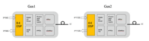
Diagram2: the first and second generation of 400Gb/s optical modules based on single-wavelength 100Gb/s
In terms of optical interface technology, the 400Gb/s 500m DR4 optical module based on single-mode fiber has come into commercial use, and there are three types of solutions: EML, DML, and silicon photonics. Among them, the EML solution is the traditional solution with the highest maturity. At the end of 2020, Lumentum released a 100Gb/s PAM4 DML chip to provide strong support for the DML solution, which requires temperature control to ensure bandwidth performance at standard temperature (0~70°C). In terms of electronic chips, the industry lacked single-wave 100Gbs/s PAM4 DML supporting electronic chips in the early days. At present, optical communication companies like Insica, and Aluksen have launched Driver and TIA-related products, but the maturity of the industry chain still needs to be further improved.
The investment and R&D enthusiasm for silicon photonics solutions is high. Intel, Lumentum, II-VI, Acacia, FiberMall, and other companies have launched 400Gb/s DR4 silicon photonics module products, and Alibaba has also released self-developed silicon photonics modules. The silicon photonics solutions of various manufacturers in the industry are not uniform, which brings certain challenges to the formation of scale advantages. Due to factors such as high coupling loss, high-power CW DFB lasers, and large-swing drivers, the silicon photonics solution is still far from industry expectations in terms of power consumption. In addition, there is also controversy in the industry on the choice of CWDM4 and PSM4 technical solutions in 500m application scenarios. Both have their own pros and cons, so various factors such as performance and cost need to be comprehensively considered.
| EML Solution | DML Solution | Silicon Photonics Solutions | |
|---|---|---|---|
| Power Consumtion | Moderate | Low | Moderate |
| Cost | Moderate | Low | Depends on pass rate at scale |
| Maturity | High | Low | Moderate |
| Key technology | _ | High bandwidth linear DML、DML Driver | Low power modulator |
| Solution | CWDM4 | PSM4 or CWDM4 | PSM4 |
| Number of pigtails | 2 | 8 or 2 | 8 |
| Fiber splice | LC/UCD/SN/MDC | MPO/LC/UCD/SN/MDC | MPO/UCD/SN/MDC |
Table5: Comparison of 400Gb/s 500m DR4 technical solutions
The 400Gb/s DR4+ optical module further expands the transmission distance to 2km, currently with the EML solution as the main solution. 100Gb/s DR and 100Gb/s FR1 optical modules mainly adopted the QSFP28 form factor, and are used in 500m and 2km breakout cable scenarios with 400Gb/s DR4 and 400Gb/s DR4+ optical modules respectively. The breakout scenario is currently used in large OTTs in North America. The advantage is that it can realize the practicability and flexibility of service signal interconnection and effectively improve port density; the disadvantage is that the maintenance is complicated and the types of modules are increased. The failure or replacement of any link will affect the other links. The 400Gb/s 2km FR4 application scenario mainly adopts the CWDM4 technical solution, which can greatly reduce the demand for optical fibers and achieve end-to-end cost advantages. At the same time, due to a large number of optical modules with different transmission distances, some domestic OTTs expect to use the 400Gb/s 2km FR4 solution to realize the unified bearer of 500m and 2km to reduce the complexity of operation and maintenance. At present, 100/400Gb/s optical module products based on single-wavelength 100Gb/s have been mass-produced by many manufacturers around the world.
| Type | Form factor | Representative domestic and foreign manufacturers | |
|---|---|---|---|
| EML | Silicon photonics/DML | ||
| 100G DR | QSFP28/ SFP56-DD | Cisco,Juniper,FiberMall,II-VI | Intel |
| 100G FRI | QSFP28/ SFP56-DD | Cisco,Juniper,FiberMall | Intel |
| 400G DR4 | QSFP-DD | Cisco,Arista,Juniper,II-VI,FiberMall | Intel,II-VI, AOI(DML) |
| 400G DR4+ | QSFP-DD | Broadcom | Intel |
| 400G FR4 | QSFP-DD | Juniper,FiberMall,II-VI,Cisco,Arista | _ |
Table 6: Representative optical module manufacturers of 100Gb/s DR/FR1 and 400Gb/s DR4/DR4+/FR4
| Device classification | Key chip | Representative manufaturer | |
|---|---|---|---|
| 500m | 2km | ||
| Optical chip | 53GBaud detector | Broadcom、GCS | Broadcom、GCS |
| 53GBaud laser | Lumentum、II-VI、AOI(DML) | Mitsubishi、Lumentum、Broadcom(EML) | |
| Electric chip | 53GBaud linear TIA | Inphi、Broadcom、 Semtech、Macom | Inphi、Broadcom、 Semtech、Macom |
| 53GBaud linear Driver | Inphi、Broadcom、 Semtech、Macom | Inphi、Broadcom、 Semtech、Macom | |
| DSP | Inphi、Broadcom | Inphi、Broadcom | |
| Silicon photonics integrated chip | Intel、Acaica、 Rockley | Intel、Acaica、 Rockley | |
Table7: Representative manufacturers of 100/400Gb/s 500m/2km optical module core photoelectric chip device
(2)10km/40km 100/400Gb/s optical transceivers
The mainstream technical solutions of 10km/40km 100/400Gb/s optical modules are shown in Table 8. The transmitting side of the 100Gb/s LR1 optical module uses a 53GBaud EML chip and has two form factor solutions: BOX and TO. The latter has the advantage of low cost, but the bandwidth margin is small and the pass rate is slightly lower. 53GBaud un-cooled EML has the advantages of low cost and low power consumption. It is currently used in scenarios of 2km and below, and the application of 10km needs to be further verified. The receiving side uses a 53GBaud PIN chip, with the coexistence of BOX and TO, airtight, and non-hermetic form factor, which may evolve to TO hermetic form factor and COB non-hermetic form factor in the future.
| Module type | Form factor | Electrical interface | Optical interface | Optical chip | OSA Form factor |
|---|---|---|---|---|---|
| 100Gb/s LR1 | QSFP28 | 4x25G NRZ | 1x 100G PAM4 | EML+ PIN | TO/BOX |
| 100Gb/s ER1 | QSFP28 | 4x25G NRZ | 1x 100G PAM4 | EML+ APD | TO/BOX |
| 400Gb/s LR4 | QSFP-DD | 8x50G PAM4 | 4x 100G PAM4 | EML+ PIN | COB/BOX |
| 400Gb/s ER4 | QSFP-DD | 8x50G PAM4 | 4x 100G PAM4 | EML+ APD EML+(SOA+PIN) | BOX |
Table8: 100/400Gb/s 10/40km mainstream technical solutions
The block diagram of the 100Gb/s LR1/ER1 optical module is shown in Figures (a) and (b) below. The transmitter uses a 53GBaud EML chip; the receiver uses a 53GBaud PIN/APD chip, and the 4:1 PAM4 DSP chip supports KP4 FEC. The block diagrams of 400Gb/s LR4 and ER4 optical modules are shown in Diagram (c) and (d) respectively. The 400Gb/s LR4 transmitter uses 4×53GBaud EML array chips (BOX/COB form factor), and the receiver uses a 4×53GBaud PIN Array chip (BOX/COB form factor; airtight and non-airtight coexistence); 400Gb/s ER4 transmitter adopts 4×53GBd EML array chip (BOX package), with wavelength selection to be determined; receiver solution is to be determined, with high-performance APD and SOA+PIN solutions being possible (BOX/COB package, coexistence of airtight and non-airtight form factor). The 400Gb/s LR4/ER4 optical module adopts an 8:4 PAM4 DSP chip and supports KP4 FEC. Compared with traditional solutions, 100/400Gb/s optical modules based on single-wavelength 100Gb/s technology can save multiple optical chips, thereby reducing cost, power consumption, and manufacturing complexity, and improving pass rate. The electronic chip adopts DSP with integrated Driver, CDR, and Gearbox functions, which reduces the design complexity and facilitates the product focus for chip designers.
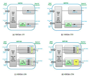
Diagram3: 100/400Gb/s optical modules based on single wave 100Gb/s technology
At present, a number of domestic and foreign manufacturers have released mass-produced products and road signs based on single-wavelength 100Gb/s technology:
-
100Gb/s LR1 has been supplied by several module manufacturers in batches. With the gradual maturity of 53GBaud optical device packaging technology, the qualification rate of optical module products has gradually improved, and the current cost is expected to be better than that of the 100Gb/s LR4 solution;
-
As for 400Gb/s LR4, a number of module manufacturers can provide Beta samples, and the cost is expected to be better than that of the 400Gb/s LR8 solution. With the gradual increase in the demand for 53GBaud optical chips in the future, there is a large room for cost reduction;
-
100Gb/s ER1 and 400Gb/s ER4 are currently under research by several module manufacturers. The 100Gb/s ER1 has made a preliminary breakthrough and can achieve 40km transmission in the laboratory environment. 400Gb/s ER4 is under research, and a prototype is expected to be launched by the end of 2022 based on the good foundation of the 100G ER1. Both 100Gb/s ER1 and 400Gb/s ER4 currently face challenges such as high optical coupling efficiency requirements at the transmitting end, high chip sensitivity requirements at the receiving end, and the need for screening.
| Type | Form factor | Representative optical module manufacturers | |
|---|---|---|---|
| Airtightness | Non-airtightness | ||
| 100G LR1 | QSFP28 | CIG、FiberMall、Juniper、 AOI、Cisco | II-VI |
| 100G ER1 | QSFP28 | Sifotonics、AOI、FiberMall | _ |
| 400G LR4 | QSFP-DD | SEDI、Juniper、FiberMall、AOI | Molex、CIG、II-VI |
| 400G ER4 | QSFP-DD | FiberMall、Cisco | _ |
Table9:Representative optical module manufacturers of 100Gb/s LR1/ER1 and 400Gb/s LR4/ER4
The core photoelectric chip devices of the single-wave 100Gb/s PAM4 technology are mainly produced by foreign manufacturers, and some domestic manufacturers have made progress at the current stage. The qualification rate of screening 53GBaud EML lasers from 25GBaud EML lasers is low, and chip structure design, material doping, etc. are needed to be optimized, so as to solve the challenges and problems of increasing bandwidth while ensuring reliability. The 53GBaud APD detector chip is relatively mature at home and abroad, and the domestic products have excellent performance. The PAM4 DSP chip has developed rapidly in China in the past two years with the 50Gb/s rate having samples in small batches and good test performance. The 100Gb/s and 400Gb/s products are in the research and development stage.
| Device classification | Key chip | Representative manufaturer | |
|---|---|---|---|
| 10km | 40km | ||
| Optical chip | 53GBaud EML | Mitsubishi、SEDI、Lumentum、Broadcom、NeoPhotonics | Mitsubishi、SEDI、Lumentum、Broadcom、NeoPhotonics |
| 53GBaud PIN | Kyosemi、GCS、Albis | _ | |
| 53GBaud APD | _ | Macom | |
| Electric chip | 53GBaud linear TIA | Inphi、Semtech、Macom | Inphi、Semtech、Macom |
| DSP | Inphi、Broadcom | Inphi、Broadcom | |
Table10: 100Gb/s 10/40km core optoelectronic chip device of the optical module
| Device classification | Key chip | Representative manufaturer | |
|---|---|---|---|
| 10km | 40km | ||
| Optical device | 53 GBaud CWDM EML | Mitsubishi,SEDI,lumentum,Broadcom,NeoPhotonics | _ |
| 53 GBaud nLWDM EML | _ | Mitsubishi,SEDI,lumentum,Broadcom,NeoPhotonics | |
| 53 GBaud PIN | Kyosemi,GCS,Albis | _ | |
| 53 GBaud APD | _ | Macom | |
| Electric chip | 53 GBaud linear TIA | Inphi,Semtech,Macom | Inphi,Semtech,Macom |
| DSP | Inphi,Broadcom | Inphi,Broadcom | |
Table11:400Gb/s 10/40km core optoelectronic chip device of the optical module
In terms of application and deployment, 100Gb/s LR1 and 400Gb/s LR4 optical module products have basically grown into maturity, and shipments have gradually increased based on market demand; 100Gb/s ER1 and 400Gb/s ER4 are expected to become commercially available in mid-2022. 100/400Gb/s optical modules based on single-wavelength 100Gb/s technology have also begun to occupy an important position in the blueprint of operator deployment and equipment vendor integration, and there will be a large demand for them in the next few years. According to the mode of carriers’ bearer network, 30/40km optical modules are mainly used in wireless middle-haul and back-haul scenarios. When 100Gb/s ER1 has a cost advantage, it will become a strong contender with the existing 100Gb/s ER4. In the future, the market may support OTN 400Gb/s signal requirements on the basis of supporting Ethernet applications and further discussion is needed for enhancing the application space of 100Gb/s ER1 and 400Gb/s ER4.
(3) 50/100/400Gb/s 80~120km optical module
For the transmission distance of 80~120km, the coherent DWDM technology can solve the link dispersion problem through DSP, reduce the optical signal-to-noise ratio requirement, and have good performance. In order to further reduce power consumption, cost, and occupied space, the industry is also actively exploring DWDM color and gray light technology solutions with direct modulation and detection technology for 80~120km transmission distance.
| Solution | Modulation code | Wave band | Channel Spacing | Channel number | FEC Type | Dispersion compensation | Power efficiency | Fiber capacity | Form factor | Relative cost | |
|---|---|---|---|---|---|---|---|---|---|---|---|
| Colored light | Coherence | 100G DQPSK | C | 100 GHz | 48/96 | CFEC | FEC | 18W/100G | 4.8/9.6 Tb/s | QSFP-DD/ CFP2-DCO/ CFP | 3 |
| 400G 16QAM | C | 100 GHz | 48 | CFEC | FEC | 5W/100G | 19.2 Tb/s | QSFP-DD/ CFP2-DCO/ OSFP/ CFP-16L | 8 | ||
| Direct mudulation and detection | 50G PAM4 | C | 50 GHz | 80 | KR4/KP4 /IFEC/SFEC | External dispersion compensation is required beyond ±100ps | 4.5W/100G | 4 Tb/s | QSFP28 | 1 | |
| 100G PAM4 | C | 100 GHz | 80 | KR4/KP4 /IFEC/SFEC | External dispersion compensation is required beyond ±40ps | 4.5W/100G | 8 Tb/s | QSFP28 | 1.5 | ||
| Gray light | Direct mudulation and detection | 4X25G NRZ | O | _ | _ | KR4 | No dispersion compensation required | 6.5W/100G | 100 Gb/s | QSFP28 | 0.5 |
Table12:Comparison of 100G/400G 80~120km technical solutions
Conclusion:
The rapid development and construction of data centers have brought opportunities and vitality to the optical module market. At the same time, they have also raised new demands and higher challenges for optical modules such as high speed, high performance, low power consumption, low cost, and intelligence. Strengthening technological innovation, guiding market agglomeration, and strengthening industrial base support are effective means of coping with those challenges. All parties in the industry and the upstream and downstream industrial chain need to form a joint force and promote coordinated progress. In terms of technological innovation, R&D and innovation of technologies such as new materials, new designs, new processes, new packaging, and new frequency bands are used to meet the new demands for optical modules in various application scenarios.
Related Products:
-
 NVIDIA(Mellanox) MMA1T00-VS Compatible 200G Ethernet QSFP56 SR4 PAM4 850nm 100m MTP/MPO APC OM3 FEC Optical Transceiver Module
$139.00
NVIDIA(Mellanox) MMA1T00-VS Compatible 200G Ethernet QSFP56 SR4 PAM4 850nm 100m MTP/MPO APC OM3 FEC Optical Transceiver Module
$139.00
-
NVIDIA(Mellanox) MMS1W50-HM Compatible 200G InfiniBand HDR QSFP56 FR4 PAM4 CWDM4 2km LC SMF FEC Optical Transceiver Module
$650.00
-
NVIDIA(Mellanox) QMMA1U00-WS Compatible 400G QSFP-DD SR8 PAM4 850nm 100m MTP/MPO OM3 FEC Optical Transceiver Module
$149.00
-
Cisco QDD-400G-DR4-S Compatible 400G QSFP-DD DR4 PAM4 1310nm 500m MTP/MPO SMF FEC Optical Transceiver Module
$400.00
-
Cisco QDD-400G-FR4-S Compatible 400G QSFP-DD FR4 PAM4 CWDM4 2km LC SMF FEC Optical Transceiver Module
$500.00
-
Cisco QDD-4X100G-LR-S Compatible 400G QSFP-DD PLR4 PAM4 1310nm 10km MTP/MPO-12 SMF FEC Optical Transceiver Module
$1000.00
-
Q28-2DW2324-80C 100G DWDM QSFP28 PAM4 80km C23 C24 100GHz CS DDM Optical Transceiver
$1600.00
-
Cisco CFP2-WDM-DETS-1HL= Compatible 200G Coherent CFP2-DCO C-band Tunable Optical Transceiver Module
$6500.00
-
NVIDIA(Mellanox) MCP1650-H01AE30 Compatible 1.5m (5ft) Infiniband HDR 200G QSFP56 to QSFP56 PAM4 Passive Direct Attach Copper Twinax Cable
$60.00
-
QSFP-DD-200G-AOC-10M 10m (33ft) 200G QSFP-DD to QSFP-DD Active Optical Cable
$595.00