
The 18-channel CWDM mux demux can look like the safest purchase: room to grow, one part number, and no second trip to procurement.
Then the link budget arrives. An 18-channel unit may add around 5.0 to 5.4 dB of insertion loss, while an 8-channel unit may add around 2.4 dB. That 2.6 to 3.0 dB difference can consume much of the margin on an 80 km span before a single transceiver is powered up.
Most buyers compare channel counts and prices. The datasheet points to a more important question: how many decibels does this module add to the link, and can the span afford them?
This guide explains the typical loss figures by channel count, the specifications that matter, the port options worth considering, and a worked 80 km link-budget example. If you already know your channel count, compare the 4-channel and 8-channel LGX modules as you read. The rest of the guide explains which configuration your span can support.
What Is a CWDM Mux Demux?
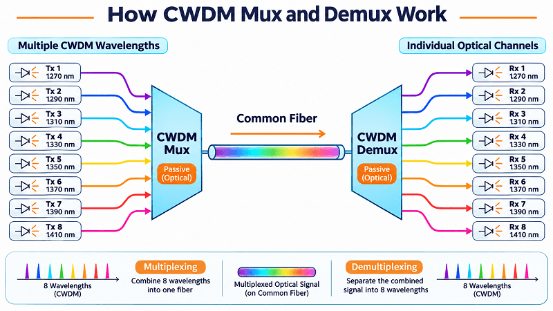
A CWDM mux demux is a passive optical module that combines multiple coarse wavelength division multiplexing channels onto a common fiber and separates them at the far end. The standard ITU-T G.694.2 CWDM grid supports up to 18 channels at 20 nm spacing. The module draws no power and is transparent to data rate and protocol, provided the optical specifications of the complete link are met.
A multiplexer (mux) combines wavelengths, while a demultiplexer (demux) separates them. Many passive CWDM assemblies package both functions in one unit. The terms “mux,” “demux,” and “mux/demux” describe the function or configuration, rather than necessarily indicating three different technologies.
The filters used in passive CWDM modules are generally bidirectional, so a filter path can operate in either direction. In a typical dual-fiber link, each end uses a matching dual-fiber mux/demux unit: one path multiplexes outbound wavelengths onto the transmit fiber, while the other demultiplexes incoming wavelengths from the receive fiber. The two ends normally use the same wavelength plan.
If you want the wider picture first, the CWDM complete guide covers the grid, transceivers, and reach limits. This page focuses on the module itself.
The Ports You Will See
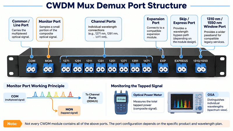
A CWDM mux demux has channel ports and one or more common or line ports. The exact layout depends on whether the module is a standalone mux, a standalone demux, or a combined dual-fiber mux/demux unit. Optional ports add flexibility, but their insertion loss and wavelength compatibility must be checked.
- Common or line port. Carries the combined wavelengths on the line fiber. A dual-fiber mux/demux unit typically has separate transmit and receive common ports.
- Channel ports. One port for each wavelength, mapped to a specific channel on the selected CWDM grid.
- Monitor port. Taps a small portion of the composite optical signal for monitoring. The tap ratio and monitor-port loss are model-specific. A standard optical power meter measures the total tapped power; an optical spectrum analyzer (OSA) or optical channel monitor (OCM) is needed to measure individual channel power.
- Expansion or upgrade port. Allows additional wavelength channels to be added through a compatible expansion module. Confirm the supported wavelength plan and the extra insertion loss before using it.
- Skip or express port. Provides a path for a designated wavelength or band to bypass part of the filter path, depending on the module design.
- 1310 nm or 1550 nm window. Provides a wider passband for a legacy service at the specified wavelength. Check the passband and possible overlap with the CWDM channels in the selected configuration.
The “+1” in a part name such as “8+1” usually means eight CWDM channels plus one additional window or service port. Confirm the function of that extra port in the product specification; it is not a separate CWDM channel by default.
Channel Counts on a CWDM Mux Demux
Common CWDM module configurations include 4, 8, 16, and 18 channels. Other channel counts, such as 12, and custom wavelength combinations are also available from some suppliers. The standard ITU-T G.694.2 grid supports a maximum of 18 channels, with nominal center wavelengths from 1271 nm to 1611 nm at 20 nm intervals. A product listing that claims more than 18 channels should be checked to determine whether it uses a custom wavelength plan or counts additional service ports as channels.
Insertion Loss by Channel Count
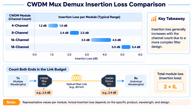
This is one of the most important specifications to compare. Higher channel-count designs often require more complex filter arrangements, but the exact loss depends on the filter architecture, wavelength, Mux or Demux direction, connectors, and optional ports.
| Module | Typical insertion loss | Grades available |
| 4-channel | ≤1.2 to 1.5 dB | Varies by supplier and configuration |
| 8-channel | ≤2.4 to 2.5 dB | Varies by supplier and configuration |
| 16-channel | About 3.5 to 3.6 dB low loss; up to about 4.5 dB standard | Some suppliers offer two grades |
| 18-channel | About 5.0 to 5.4 dB | Design-dependent; confirm the datasheet |
Treat these figures as representative values, not guaranteed limits for every product. Vendors may specify insertion loss at different wavelengths, ports, or measurement reference points. Check whether connector loss is included and whether the value applies to the Mux path, Demux path, or both. The 18-channel range reflects published product data from different designs; the exact value must be confirmed against the selected manufacturer’s datasheet.
Why More Channels Costs Decibels
A CWDM mux demux uses an optical filter arrangement to route each wavelength. Many thin-film filter designs use cascaded stages, and higher channel counts can require a more complex filter path. The additional components and stages can increase insertion loss, although the relationship is design-dependent rather than a fixed loss penalty for every added channel.
There is a second consideration that may not appear in the channel-count table. Some suppliers offer low-loss grades for higher channel counts, while others do not. More capacity can mean fewer low-loss options, so compare the actual specifications rather than assuming that every 16- or 18-channel module has the same performance.
Marco, a systems integrator in northern Italy, ordered 16-channel modules for a municipal network in early 2025. His reasoning was sound: the city had plans for six more sites. What he did not account for was the standard-grade 4.5 dB insertion loss per module on a 40 km span that already had 19 dB of fiber and splice loss.
Two of the four links came in with less than 1 dB of margin. The third failed acceptance outright. Replacing the standard-grade modules with low-loss versions recovered 1.0 dB at each end and saved the project, but it cost six weeks and required a second shipping cycle. The six spare channels remained unused for the next eighteen months.
Reading a CWDM Mux Demux Datasheet
Product pages may list eight or ten specifications. Four groups of parameters have the greatest impact on whether your link will work.
Insertion Loss
Insertion loss is the optical power loss introduced by the CWDM mux demux. It consumes part of the link budget and must be counted for every module in the signal path. In a link with a mux at one end and a demux at the other, include the loss of both devices.
That doubling is where budgets can become tight. A 2.4 dB module may sound harmless until you count both ends and see that the two modules add 4.8 dB before fiber, splice, and connector losses are included.
Isolation: Adjacent vs Non-Adjacent
Isolation measures how effectively the module prevents optical power from one channel from leaking into another. Adjacent CWDM channels are spaced 20 nm apart and are generally harder to separate, so their specified isolation is often lower: for example, ≥30 dB. Non-adjacent channels may be specified at ≥40 dB.
Thirty decibels of isolation is sufficient for many applications, but the requirement depends on the optical power levels and receiver characteristics of the channels. It deserves particular attention when a strong signal is placed next to a much weaker signal, such as when short-reach and long-reach optics share adjacent channels.
Return Loss, PDL, and PMD
Return loss (≥45 dB is a common specification) measures the amount of optical power reflected back toward the source relative to the incident power. Higher return loss is better because it means less reflected power. Poor return loss can affect reflection-sensitive transmitters and reduce system performance, so check the specifications of both the module and its connectors.
Polarization-dependent loss (PDL, often ≤0.2 dB) describes how insertion loss varies with the polarization state of the incoming light. Its impact depends on the transceiver, modulation format, receiver tolerance, and available link margin; there is no universal bit-rate threshold at which PDL suddenly becomes important.
Polarization-mode dispersion (PMD) describes the differential delay between polarization modes. Some CWDM module datasheets specify PMD, for example at ≤0.1 ps. Check the value when designing higher-speed or longer-reach links rather than assuming it is irrelevant.
Passband and the ITU ±6.5 nm Window
The passband defines the wavelength range over which a CWDM filter meets its specified optical performance. Many CWDM modules specify a passband of approximately ±6.5 nm around the nominal center wavelength, or 13 nm in total. This is a common manufacturer specification, not a universal passband requirement set by ITU-T G.694.2.
The passband matters because the wavelength of an uncooled laser can drift with temperature. Many CWDM transceivers use uncooled lasers, and a sufficiently wide passband helps accommodate this wavelength variation across the specified operating temperature range. Always check the transceiver’s wavelength tolerance against the mux/demux passband.
DWDM uses much narrower channel spacing. Common examples include 100 GHz and 50 GHz, which correspond to approximately 0.8 nm and 0.4 nm near 1550 nm. The ITU-T G.694.1 DWDM grid is defined in frequency, so the wavelength spacing is not exactly constant across the full band. Do not expect a CWDM filter to separate closely spaced DWDM channels, and do not pay for DWDM-grade channel spacing when a 20 nm CWDM grid meets the application.
Have a link-budget spreadsheet open? Send it over and our engineers can review which module and grade fit before you order. Request a link-budget review.
Single Fiber vs Dual Fiber
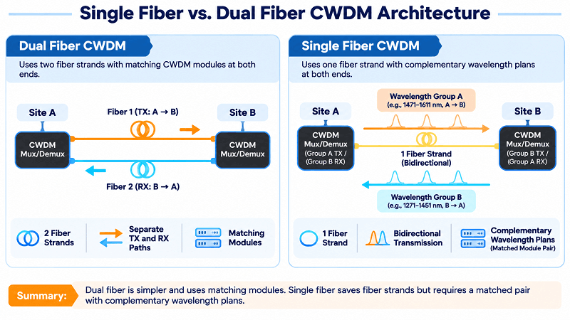
Dual fiber uses one strand to transmit and another to receive. Single fiber carries both directions over one strand by assigning different wavelength groups to the two directions.
| Dual fiber | Single fiber | |
| Strands per link | 2 | 1 |
| Modules at each end | Matching modules | Complementary modules, ordered as a pair |
| Spares to stock | Usually one part number | Usually two part numbers |
| Best fit | Owned fiber infrastructure | Leased fiber or strand shortages |
Dual fiber is the default for a reason. Both ends can use matching modules, spare management is simpler, and troubleshooting follows the usual transmit/receive logic.
Single fiber reduces the strand count and can suit leased fiber, where every fiber pair has a cost. The trade-off is greater complexity. A single-fiber CWDM pair assigns different wavelength groups to the two directions, so each end transmits on one group and receives on the other. The two modules must be designed as a matched pair and ordered with complementary wavelength plans.
For a campus with its own cable, a dual-fiber CWDM mux demux pair usually wins on simplicity. For a metro operator leasing strands between buildings, single fiber can reduce recurring fiber costs.
Packaging: LGX, 1U, and ABS
| Format | Channels per unit | Rack fit | Where it belongs |
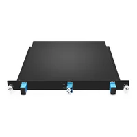
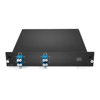
| LGX cassette | 4 to 18 | Slides into a 1U shelf; typically 4 to 8 per shelf, depending on shelf design | Metro and enterprise networks; easy to expand |
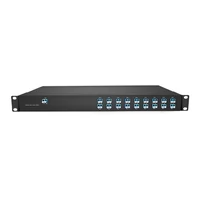
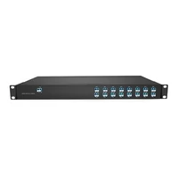
| 1U rack mount | 8 to 18 | Fixed 19-inch, 1U enclosure | Head ends and hub sites |
| ABS box | 2 to 8 | Wall or tray mount | Small sites and outside plant |
For many builds, an LGX CWDM mux demux is a practical default. It is familiar to installers, fits a standard LGX shelf, and allows another cassette to be added later without replacing the rack.
A passive CWDM mux needs no power, so the site requirements are mainly rack space, fiber routing, and clean connections. This is worth remembering when an active chassis is proposed to solve a problem that is really about port count or wavelength capacity.
The 1U format makes sense when you need multiple ports in one location and want an integrated rack-mounted assembly. ABS boxes are compact and can cost less, but may be harder to manage in larger installations. Clear port labeling is especially important when equipment is installed in a wall-mounted enclosure.
The 1310 Window and Skip Ports
Many common 8-channel CWDM configurations use nominal center wavelengths from 1471 nm to 1611 nm, often labeled as 1470 nm to 1610 nm in product specifications. The standard grid also includes a nominal 1311 nm channel. However, a “1310 nm window” is a broad passband port for a legacy 1310 nm service; it is not the same as a narrow 1311 nm CWDM channel. Because the window may overlap the lower part of the CWDM grid, the exact channel plan must be checked before ordering.
Why would you want a 1310 nm window? Many installed systems still use 1310 nm optics, including router uplinks, older OTN cards, and legacy SDH services. A compatible window port can allow that service to share the fiber with CWDM channels, provided the module’s wavelength plan keeps the signals separated.
Yusuf, a network engineer with a regional rail operator, encountered this issue during a signaling upgrade outside Ankara. The new CWDM transport carried eight channels for the control network. A legacy 1310 nm circuit for the interlocking system had to remain active during the migration.
Leasing another fiber pair for eighteen months would have cost more than the entire mux order. He specified a module with a 1310 nm window, kept the legacy circuit on the same fiber route, and retired it on schedule when the new system was cut over.
The window port on a CWDM mux demux is not loss-free. It can add insertion loss to the relevant optical path, and its passband and isolation characteristics may not be listed alongside the standard CWDM channel specifications. Ask for the measured values for the exact configuration before you commit.
FiberMall offers an 8-channel module covering 1470–1610 nm with an additional 1310 nm window. A 4-channel unit with a 1550 nm window is also available for custom wavelength plans. Because a 1550 nm window may overlap the nominal 1551 nm CWDM channel, confirm which channels are included or omitted in the selected configuration.
Water Peak and Channel Planning
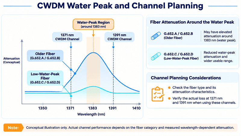
Two CWDM channels sit on either side of the 1383 nm water-peak region: nominally 1371 nm and 1391 nm. Older G.652.A and G.652.B fibers may have elevated attenuation around this region because of hydroxyl-ion (OH) absorption. G.652.C and G.652.D fibers are designed to reduce water-peak attenuation and support operation over a wider wavelength range.
Check the fiber type and its attenuation characteristics before using the 1371 nm or 1391 nm channels. On older fiber, measure or verify the actual loss at the wavelengths in use rather than automatically assuming that both channels are unusable. A quick review of the cable records and, where necessary, an optical measurement can prevent unexpected reach problems during acceptance testing.
Worked Example: 8-Channel Mux on an 80 km Link
Here is the arithmetic for a representative span: 80 km of G.652 single-mode fiber, sixteen splices, two connector pairs, and an optical link with an assumed available budget of 26 dB. The example uses a fiber attenuation coefficient of 0.22 dB/km at the selected wavelength. Actual attenuation varies with wavelength and cable specifications.
| Item | 8-channel | 18-channel |
| Mux, head end | 2.4 dB | 5.0 dB |
| Demux, tail end | 2.4 dB | 5.0 dB |
| Fiber, 80 km at 0.22 dB/km | 17.6 dB | 17.6 dB |
| Splices, 16 at 0.1 dB | 1.6 dB | 1.6 dB |
| Connectors, 2 pairs at 0.3 dB | 0.6 dB | 0.6 dB |
| Total | 24.6 dB | 29.8 dB |
| Available budget | 26.0 dB | 26.0 dB |
| Margin | +1.4 dB | -3.8 dB |
The 8-channel design uses 24.6 dB and leaves 1.4 dB of the assumed budget. That is a narrow margin and may be insufficient once the required engineering reserve and any uncounted losses are included. Confirm the transceiver budget and the actual fiber attenuation before treating the link as acceptable. The 18-channel version exceeds the assumed budget by 3.8 dB; cleaning and re-patching alone are unlikely to recover that much loss.
The 4-channel option totals 22.2 dB and leaves 3.8 dB of margin if each module contributes 1.2 dB. If each module contributes 1.5 dB, the total becomes 22.8 dB and the remaining margin is 3.2 dB. The 16-channel low-loss option, at 3.5 dB per module, totals 26.8 dB and exceeds the assumed budget by 0.8 dB. The 16-channel standard grade, at 4.5 dB per module, totals 28.8 dB and exceeds it by 2.8 dB.
Notice what the CWDM mux demux choice changes. The fiber, optics, and distance stay the same. The variable is the insertion loss of the module selected to provide the required channel capacity.
How to Choose a CWDM Mux Demux
Seven steps, in order. Doing them out of order is how modules get returned.
- Count the channels you need this year, then consider adding two for near-term growth.
- Calculate the link budget with both ends included. Count the insertion loss of the mux and demux paths.
- Choose the lowest channel count that covers your current requirement and planned growth. Check the insertion loss before comparing prices.
- Decide between single-fiber and dual-fiber operation based on the available fiber infrastructure and the cost of leasing additional strands.
- Choose packaging that your rack, shelf, or cabinet can actually accept.
- Confirm the connector polish. LC/UPC is common, but each connection must use compatible end-face types. Never mate an APC connector directly with a UPC connector. If the equipment has different interface types, use a properly specified hybrid patch cord with the correct connector polish at each end.
- Decide which optional ports are needed. A monitor port supports signal monitoring, an expansion port supports phased builds, and a window port can carry a compatible legacy service.
If step 3 leaves too little margin, you have three main options: choose a lower channel count, select a low-loss grade where available, or shorten the span. A higher-capacity module is not a solution to an insufficient optical budget.
Installation and Testing
A passive CWDM mux demux has no firmware or configuration settings. Many field issues can be traced to a connector, an incorrect port map, or a connector-polish mismatch.
Clean and inspect connectors before patching. A dirty LC ferrule can introduce more loss than the module itself and may make a healthy mux appear faulty when measured with a power meter.
Karla, a field technician in Monterrey, spent most of a shift investigating a 4 dB deficit on a new 8-channel link. The module tested clean on the bench, and the fiber tested clean. The problem was a UPC patch cord connected directly to an APC bulkhead at the demarcation point. The incompatible end-face geometries prevented proper contact, causing excessive insertion loss and poor return loss.
The fix was to replace the mismatched patch cord with a correctly specified hybrid patch cord, with a UPC connector at one end and an APC connector at the other. The replacement was inexpensive; finding the mismatch took six hours because nobody checked the connector polish at the boundary.
Test every channel path on the CWDM mux demux, not just the common port. To test a mux path, inject a calibrated signal into each channel port and measure the output at the common port. To test a demux path, inject the signal at the common port and measure the output at each channel port. Record the insertion loss for every channel. A single outlier may indicate a damaged port, a poor connector, or a fiber issue rather than a design problem.
Label every port with its wavelength, not just its channel number. The next technician will thank you, especially when replacing a failed 1551 nm optic at 2 a.m.
FAQ
What is the difference between a mux and a demux?
A multiplexer combines multiple wavelengths onto one fiber. A demultiplexer separates them. Many passive CWDM assemblies use bidirectional filter paths and package both functions in one unit, but the exact port layout depends on the module design.
How many channels does a CWDM mux support?
The standard ITU-T G.694.2 grid supports 18 channels, from 1271 nm to 1611 nm at 20 nm spacing. Common module configurations include 4, 8, 16, and 18 channels; some suppliers also offer 12-channel and custom configurations. The standard grid sets the 18-channel limit.
What insertion loss should I expect?
As a general guide, expect approximately 1.2 to 1.5 dB for a 4-channel module, 2.4 to 2.5 dB for an 8-channel module, 3.5 to 4.5 dB for a 16-channel module depending on grade, and around 5.0 to 5.4 dB for an 18-channel module. Always confirm the specification for the exact product, wavelength, and Mux or Demux path.
Do I need a monitor port?
A monitor port lets you sample the composite optical signal without disconnecting the live link. A standard optical power meter measures the total tapped power; an OSA or OCM is needed to distinguish individual channel power. A monitor port can be useful at unstaffed remote sites, but confirm its tap ratio and the additional loss it introduces.
What is the 1310 window for?
It provides a broad passband for a legacy optical service around 1310 nm. Although the standard CWDM grid includes a nominal 1311 nm channel, a 1310 nm window is a wider pass-through path and may overlap lower CWDM channels. Use it only with a wavelength plan designed to prevent channel conflicts.
Single fiber or dual fiber?
Dual fiber is simpler and generally uses matching modules at both ends. Single fiber reduces the strand count and can suit leased fiber, but requires a matched pair of modules with complementary wavelength plans and usually complicates spare management.
Can I use a CWDM mux with DWDM?
A standard CWDM channel port cannot directly separate closely spaced DWDM channels because CWDM filters use much wider passbands. However, CWDM and DWDM systems may be combined through a specifically designed expansion or upgrade-port arrangement, provided the wavelength plan and link budget are compatible. Otherwise, use separate modules or separate fibers. The CWDM vs. DWDM comparison explains where each technology fits.
The Short Version
Channel count is a capacity decision. Insertion loss is a reach decision. Buyers who treat them as the same decision can end up paying for it in the field.
Choose the smallest module that covers this year’s channels and reasonable near-term growth. Calculate the link budget with both ends included. Check the grade and the exact product datasheet, especially when using more than eight channels. Then compare prices.
FiberMall offers CWDM mux demux modules from 4 to 18 channels in LGX, 1U, and ABS formats, with 1310 nm and 1550 nm window options and custom wavelength configurations. If you would rather not do the calculations alone, send us your span details and our team can recommend a module, a grade, and the margin it leaves in your link budget.
The standard CWDM wavelength grid is defined by ITU-T G.694.2, so the nominal channel wavelengths are predictable. The insertion loss is what can surprise you if nobody checks the exact datasheet first.
Related Products:
-
 Passive CWDM Double Fiber Mux & Demux Module 18 CH (1270-1610nm) LC/UPC 1U Rack
$630.00
-
Passive CWDM Double Fiber Mux & Demux Module 16 CH (1310-1610nm) 1U Rack
$570.00
-
CWDM MUX 8CH 16 Wavelengths (TX: 1310/1330/1390/1410/1470/1490/1550/1570nm RX: 1350/1370/1430/1450/1510/1530/1590/1610nm) LC/UPC Single Fiber 1U Rack
$320.00
-
Passive CWDM Double Fiber Mux & Demux Module 8CH (1470-1610nm) LC/UPC LGX BOX
$280.00
-
CWDM MUX 4CH 8 Wavelengths (TX: 1470/1490/1510/1530nm RX: 1550/1570/1590/1610nm) with Express Port LC/UPC Single Fiber LGX BOX
$150.00
-
Passive CWDM Double Fiber Mux & Demux Module 4 CH (1470-1530nm) LC/UPC LGX BOX
$150.00
-
Passive CWDM Single Fiber 1 Channel OADM LGX BOX
$70.00
-
Passive CWDM Double Fiber 2 Channels OADM LGX BOX
$130.00
-
Passive CWDM Double Fiber 4 Channels OADM LGX BOX
$250.00
-
SFP-CW10G27-40C 10G CWDM SFP+ 1270nm 40km LC SMF DDM Transceiver Module
$95.00
-
SFP-CW10G27-10C 10G CWDM SFP+ 1270nm 10km LC SMF DDM Transceiver Module
$60.00
-
SFP-CW10G59-05C 10G CWDM SFP+ 1590nm 5km LC SMF DDM Transceiver Module
$60.00
-
SFP-CW10G27-20C 10G CWDM SFP+ 1270nm 20km LC SMF DDM Transceiver Module
$75.00
-
SFP-CW10G47-100C 10G CWDM SFP+ 1470nm 100km LC SMF DDM Transceiver Module
$280.00