
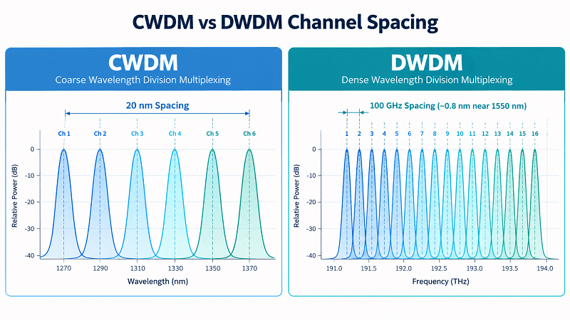
One of the fundamental differences between DWDM and CWDM is how far apart their optical wavelengths are spaced.
CWDM uses a channel spacing of 20 nanometers. DWDM packs channels much more closely, commonly using 100 GHz or 50 GHz spacing—approximately 0.8 nm or 0.4 nm near 1550 nm. This difference influences how many channels a system can support, the type of lasers and filters it requires, its amplification options, and its overall cost. Transmission reach also depends on the optical power budget, fiber characteristics, modulation format, and system design.
So if you’re weighing DWDM vs CWDM for a real project, the useful question isn’t “which one is better?” It’s “which one fits this link?” A four-channel metro access link and a 120 km regional span may require different optical architectures. The same engineer may use both technologies across different parts of a network.
This guide compares the two across channel spacing, capacity, wavelength range, reach, amplification, and cost. You’ll also get practical selection criteria, cost comparison examples, and a method for combining CWDM and DWDM on the same fiber infrastructure as traffic grows. Not sure which technology fits your project? Talk to FiberMall’s optical engineers with your span length, channel count, and capacity requirements.
DWDM vs CWDM: The Core Difference
Both technologies perform the same fundamental function. They’re forms of wavelength division multiplexing (WDM), which allows multiple independent optical signals to travel through the same fiber by assigning each signal a different wavelength of light.
The primary difference is channel spacing. CWDM stands for coarse wavelength division multiplexing and uses widely spaced wavelengths. DWDM stands for dense wavelength division multiplexing and uses much narrower frequency spacing.
That difference affects system design in three important ways.
- Laser tolerance. Wider spacing allows greater wavelength drift, so conventional CWDM transceivers can often use uncooled lasers. DWDM requires tighter wavelength accuracy and stability, commonly achieved through temperature control, wavelength monitoring, or other stabilization techniques.
- Channel count. Wider spacing limits the number of wavelength channels within a given optical spectrum. Narrower spacing allows DWDM systems to support substantially more channels within the same spectral range.
- Amplification. DWDM channels are commonly concentrated within optical bands supported by mature amplifier technologies, particularly C-band and L-band EDFAs. CWDM wavelengths extend across a much wider spectrum, making simultaneous amplification of all channels more challenging.
Channel spacing is a major factor behind these trade-offs, but it is not the only one. Actual network performance also depends on the optical components, transmission format, fiber type, and link design.
For the full technical background on dense wavelength multiplexing, see our DWDM complete guide.
DWDM vs CWDM Comparison Table
| Parameter | CWDM | DWDM |
| Channel spacing | 20 nm | 0.4 to 0.8 nm (50 or 100 GHz) |
| Channel count per fiber | Up to 18 (8 to 16 typical) | 40 to 160+ |
| Wavelength range | 1270 to 1610 nm (O through L band) | C-band 1530 to 1565 nm; L-band to about 1625 nm |
| Light source | Uncooled laser | Temperature-stabilized, frequency-locked laser |
| Amplification | Not practical | EDFA across the C-band |
| Typical reach | Up to 80 km (about 70 km at 10G) | 80 to 120 km unamplified, hundreds of km amplified |
| Speed per channel | Up to 10G | 100G and 200G common, 400G emerging |
| Relative cost | Lower | Higher |
| Typical use | Metro, access, campus, 5G fronthaul | Long-haul, backbone, data center interconnect |
Read the table from top to bottom, and a clear pattern emerges. CWDM prioritizes simplicity and cost efficiency for relatively modest channel counts, while DWDM prioritizes spectral efficiency, capacity scalability, and compatibility with advanced optical transport systems.
The best choice depends on how these characteristics align with the requirements of the actual link.
Channel Spacing and Capacity: 18 Channels vs 160+
The difference in channel spacing becomes especially apparent when comparing how many independent optical channels each technology can carry.
CWDM: 20 nm Spacing and the 18-Channel Ceiling
CWDM follows the ITU-T G.694.2 wavelength grid, which defines 18 nominal center wavelengths spaced 20 nm apart, from 1271 nm to 1611 nm. These wavelengths are also commonly identified in commercial products using the legacy 1270–1610 nm labels. Many practical CWDM networks use 8 to 16 channels, although the standardized grid supports 18.
Why not use all 18? Some lower-wavelength channels fall near the water-peak absorption region around 1383 nm, where older conventional single-mode fiber may exhibit higher attenuation. On legacy fiber, operators may avoid certain channels or limit their reach. Modern low-water-peak fiber improves the usability of these wavelengths and can support a wider range of CWDM channels.
The wide spacing also provides an important cost advantage. A conventional CWDM laser can tolerate greater wavelength variation than a DWDM laser, often allowing it to operate without active temperature stabilization. This simplifies transceiver design and can reduce both power consumption and equipment cost.
DWDM: 0.8 nm Spacing and the 160-Channel Grid
DWDM follows the ITU-T G.694.1 frequency grid, which supports common channel spacings of 100 GHz and 50 GHz, corresponding to approximately 0.8 nm and 0.4 nm near 1550 nm. Other fixed-grid spacings, including 200 GHz and 25 GHz, are also available. Flexible-grid DWDM additionally allows frequency slots to be allocated with 12.5 GHz slot-width granularity, supporting more efficient spectrum allocation for different transmission formats.
Tighter spacing allows many more channels to fit within the usable optical spectrum. Common DWDM configurations support 40, 80, or 96 channels, while denser configurations can reach 160 or more channels when suitable optical bandwidth and filtering technologies are available.
For example, 96 independent channels operating at a nominal client data rate of 100 Gb/s provide an aggregate client-side capacity of approximately 9.6 Tb/s. The actual line-side capacity, spectral occupancy, and usable throughput depend on the modulation format, FEC overhead, and transceiver architecture.
That density comes with additional engineering requirements. DWDM transmitters need tighter frequency accuracy and wavelength stability. Many implementations use temperature control, wavelength monitoring, or active stabilization to maintain reliable operation within the selected channel grid.
For the complete frequency plan, see our guide to the DWDM channel plan and ITU grid.
Reach, Amplification, and Why CWDM Is Commonly Limited to Shorter Links
Distance is often a decisive factor when choosing between CWDM and DWDM. The difference is closely related to optical amplification, but actual transmission reach also depends on link loss, chromatic dispersion, receiver performance, and the transmission technology used.
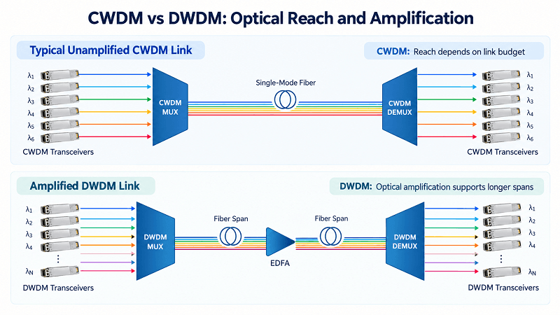
Why Conventional EDFAs Are Less Suitable for CWDM
The erbium-doped fiber amplifier (EDFA) is widely used in DWDM networks. Conventional C-band EDFAs amplify optical signals over a wavelength range of approximately 1530–1565 nm, allowing multiple DWDM channels within the amplifier’s operating band to be amplified simultaneously without optical-to-electrical conversion.
CWDM channels, however, extend across the O, E, S, C, and L bands, from 1271 nm to 1611 nm. Most of these wavelengths fall outside the operating range of a conventional C-band EDFA.
As a result, a standard C-band EDFA cannot simultaneously amplify the entire CWDM wavelength range.
This does not mean CWDM signals can never be optically amplified. Selected CWDM wavelengths within a compatible amplifier’s gain bandwidth can be amplified, and specialized optical amplification technologies may support other wavelength regions. However, these approaches generally introduce additional cost, complexity, or design constraints.
For conventional CWDM systems without optical amplification, each channel must meet the required receiver sensitivity and link margin after accounting for fiber attenuation, multiplexer insertion loss, connector loss, and other impairments. If the link cannot meet these requirements, higher-budget optics, alternative wavelengths, regeneration, or a different transport architecture may be necessary.
The Real CWDM Distance Limits
CWDM is often described as an 80 km technology. That figure is a common deployment reference rather than a fixed technical limit.
Practical reach depends on the operating wavelength, transceiver specifications, data rate, fiber attenuation, chromatic dispersion, and total optical link budget.
At 1G, certain high-power CWDM transceivers can support links well beyond 80 km under suitable conditions. At 10G, conventional CWDM systems are frequently designed for shorter distances, although specialized long-reach transceivers and carefully engineered links can extend their operating range.
Fiber characteristics also matter. On older single-mode fiber, increased attenuation around the water-peak region may restrict the usable wavelength range or shorten the reach of certain CWDM channels. Low-water-peak fiber reduces this limitation.
Consider an illustrative example involving Priya, a network planner at a regional ISP. She needs to connect two towns over a 120 km optical route and initially considers CWDM to minimize transceiver costs.
A preliminary power-budget calculation suggests that certain high-power optics might support the span. However, detailed engineering reveals additional losses from the mux/demux equipment, fiber connections, and aging margin. The selected 10G CWDM transceivers cannot meet the complete link requirements.
The team must evaluate higher-budget optics, regeneration, or an alternative DWDM design with suitable amplification.
The lesson is not that CWDM always fails at 120 km. It is that selecting CWDM solely on the basis of lower module prices can create additional costs if the complete optical link budget and deployment requirements are not considered.
DWDM Reach with EDFA
DWDM provides more practical options for optical amplification, particularly when channels are concentrated within the C-band or L-band.
A suitable EDFA can amplify multiple DWDM channels simultaneously, helping compensate for fiber and component losses. This makes DWDM well suited to longer routes and networks with multiple intermediate optical nodes.
Some unamplified DWDM links can operate over distances of approximately 80–120 km, depending on the transceiver type, optical power budget, modulation format, and fiber characteristics. However, this range should not be treated as a universal design limit.
For amplified systems, EDFAs may be installed at suitable intervals, often around 60–80 km in conventional terrestrial long-haul applications, although actual amplifier spacing is determined by span loss and system design.
With properly engineered optical amplification, coherent transmission, and sufficient optical signal-to-noise ratio (OSNR), DWDM systems can support hundreds or even thousands of kilometers.
Optical amplification alone does not guarantee unlimited reach. Amplified spontaneous emission noise, chromatic dispersion, fiber nonlinearities, modulation format, and FEC performance must all be considered.
These capabilities make DWDM a widely adopted technology for long-haul, submarine, regional, and intercity optical transport networks.
For more information on the amplifier side, see our DWDM amplifier and EDFA guide.
Cost: Module Price vs Cost Per Usable Channel
Cost is one of the most common sources of confusion in the CWDM vs DWDM comparison. CWDM transceivers are often less expensive in conventional deployments, but module price alone does not determine the most cost-effective network architecture.
The more useful question is how much the complete system costs for the capacity, distance, and scalability the project requires.
What Each System Actually Costs
A conventional CWDM system generally has a lower initial equipment cost when only a small number of wavelengths are required.
Uncooled lasers, relatively simple filters, and the absence of optical amplification in many deployments help reduce hardware complexity. For short and medium-distance applications with modest capacity requirements, CWDM can provide an economical solution.
DWDM systems may require more sophisticated transceivers, tighter wavelength control, higher-performance multiplexers, and additional optical amplification equipment for longer routes.
However, the added cost provides greater spectral efficiency and a wider range of capacity expansion options.
The actual price difference depends on channel count, transceiver specifications, wavelength tunability, transmission distance, equipment compatibility, and vendor pricing. There is no universal cost ratio that applies to every CWDM and DWDM deployment.
The Number That Matters: Cost Per Usable Channel
A more meaningful comparison considers the total cost per usable channel over the required transmission distance.
This approach includes not only transceiver and mux/demux costs but also fiber availability, installation, power consumption, maintenance, regeneration requirements, and future upgrades.
Consider Marcus, an IT manager planning connectivity for a manufacturing campus with four sites and a longest optical span of 35 km.
A vendor proposes a DWDM system with tunable optics and expansion-ready equipment. However, Marcus needs only four independent wavelength channels, with limited growth expected over the system’s lifetime.
Assuming the optical power budget and bandwidth requirements are satisfied, a CWDM mux/demux and four appropriately specified CWDM transceiver pairs could meet the same requirement with lower equipment complexity and potentially lower total cost.
Now consider a different scenario.
A regional network requires 20 independent wavelength channels over a 120 km span. A conventional 18-channel CWDM grid cannot accommodate all 20 channels on one fiber transmission direction, and the long span may introduce additional optical power-budget challenges.
The operator could consider additional fibers, separate WDM systems, regeneration, or alternative equipment. A DWDM architecture may offer better scalability and a lower total cost per usable channel, particularly when fiber resources are limited.
The economics are therefore different for each deployment.
There is no fixed break-even point at 80 km or 16 channels. CWDM may be the more economical choice for some links beyond those values, while DWDM may be justified at shorter distances when high channel density or future expansion is important.
Third-Party Optics and Total Cost
DWDM is not necessarily more expensive at the transceiver level in every case.
Third-party compatible optics can significantly reduce equipment procurement costs for both CWDM and DWDM deployments, depending on product specifications, compatibility requirements, and supplier pricing.
In some cases, a third-party 10G DWDM transceiver may be competitively priced against a comparable CWDM model.
This reinforces the importance of comparing complete system costs rather than assuming that one technology will always have a higher module price.
Sourcing optics for a mixed WDM network? Explore FiberMall’s CWDM and DWDM mux/demux portfolio alongside compatible CWDM and DWDM transceivers, all from one supplier.
When to Choose CWDM vs DWDM
With the technical differences established, the choice becomes a matter of matching the optical architecture to the application.
Choose CWDM when:
- The required transmission distance can be supported by available CWDM optics and the calculated optical link budget, commonly for links under approximately 80 km.
- You need a relatively small number of channels, typically 16 or fewer, with limited future expansion.
- You own or have access to sufficient dark fiber and want to minimize equipment complexity and initial cost.
- Low power consumption and simple deployment are priorities, particularly for campus networks, metro access, enterprise connectivity, or 5G fronthaul applications.
Choose DWDM when:
- The link requires longer transmission distances or optical amplification, particularly across regional and long-haul routes.
- You need more channels than a conventional CWDM system can support on the available fiber.
- Fiber resources are scarce, leased, or expensive, making capacity per fiber strand an important consideration.
- You expect substantial capacity growth and want to expand from a small number of wavelength channels to 40, 80, or more, subject to the selected system architecture and spectral bandwidth.
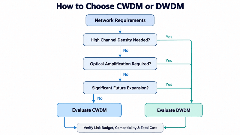
Four key questions can guide most deployment decisions:
- What is the maximum transmission distance today, and how might it change over the next five years?
- How many independent wavelength channels are required now, and what is the expected growth?
- Is the fiber owned, leased, or limited in availability?
- Does the network require optical amplification, intermediate add/drop nodes, or future high-capacity upgrades?
If the required distance and channel count are modest, CWDM is often a practical and cost-effective solution.
If capacity density, amplification, or long-term scalability becomes more important, DWDM may offer greater value.
Deployment teams using both technologies generally evaluate transmission distance, available fiber, scalability, and total system cost rather than relying on module prices alone. Industry comparisons, including those published by WWT, emphasize the importance of matching the technology to actual network requirements.
Hybrid CWDM + DWDM: Running Both on One Fiber
CWDM and DWDM are not mutually exclusive. Their operating wavelength ranges overlap, particularly around the commercially designated 1530 nm and 1550 nm CWDM channels, creating opportunities for hybrid WDM architectures.
However, combining the two technologies requires more than simply connecting any DWDM mux/demux to a CWDM port.
How Hybrid CWDM and DWDM Works
CWDM divides a broad optical spectrum into widely spaced wavelength channels. DWDM concentrates multiple tightly spaced channels within a narrower spectral region.
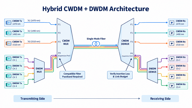
In a compatible hybrid design, selected DWDM wavelengths can be carried through a suitable CWDM channel passband or a dedicated expansion port.
For example, the line port of a DWDM mux/demux may be connected to a compatible CWDM mux/demux channel port, provided that the DWDM channels fall within the CWDM filter’s effective passband.
This allows multiple DWDM channels to occupy a portion of the optical spectrum allocated to a wider CWDM channel.
The actual number of DWDM channels that can pass through the CWDM filter depends on its passband width, insertion-loss characteristics, isolation, and the selected DWDM frequency grid.
Not all CWDM mux/demux products support this configuration, and not every DWDM channel within the C-band can be passed through a single CWDM channel port.
Expanding an Existing CWDM Network
Consider an illustrative metro operator running a CWDM ring across ten sites.
As traffic increases, the operator needs additional wavelength capacity but wants to avoid replacing the existing fiber infrastructure.
Instead of rebuilding the network immediately, the engineering team evaluates whether an unused CWDM channel port or a dedicated expansion port can accommodate a compatible DWDM channel group.
If the installed filters, optical link budget, and node configurations support the design, a DWDM mux/demux can be integrated to provide additional channels over the same fiber route.
This type of upgrade can preserve much of the existing CWDM infrastructure while increasing available capacity.
However, expansion may still require changes to filters, add/drop modules, transceivers, or intermediate nodes. Ring protection and restoration behavior must also be reviewed separately, particularly when new DWDM services share the existing optical path.
Engineering Considerations for Hybrid WDM
Hybrid designs require careful wavelength planning and optical validation.
Engineers should verify wavelength compatibility, the CWDM filter passband, channel isolation, and the insertion loss introduced by cascading mux/demux stages.
The complete optical power budget must account for losses at both ends of the link and at any intermediate add/drop nodes.
For amplified or high-speed coherent systems, OSNR and other transmission impairments must also be evaluated.
When these requirements are satisfied, hybrid CWDM/DWDM can provide a cost-effective way to increase capacity on an existing fiber network without necessarily replacing the entire optical infrastructure.
Our DWDM mux/demux selection guide covers the component choices involved in these architectures.
Optics and Equipment for Each
Although CWDM and DWDM share the same fundamental WDM principle, their equipment requirements can differ significantly.
CWDM Equipment
A conventional CWDM deployment typically requires a CWDM mux/demux with 8, 16, or 18 channels, along with wavelength-matched optical transceivers.
Common transceiver form factors include SFP and SFP+, depending on the required data rate and host interface.
Many CWDM applications operate without optical amplifiers, simplifying installation and maintenance.
The selected transceivers must match the host device’s interface type, supported data rate, and compatibility requirements.
For example, a 10G CWDM SFP+ transceiver must be installed in a compatible 10G-capable port. The presence of an SFP or QSFP port alone does not guarantee support for a particular CWDM transceiver or data rate.
DWDM Equipment
A DWDM deployment may require a more extensive range of optical components.
Common equipment includes 40-channel or 80-channel DWDM mux/demux units, including AWG-based devices, OADMs or ROADMs for intermediate optical nodes, and fixed-wavelength or tunable DWDM transceivers.
Longer routes may also require EDFAs, optical supervisory functions, monitoring systems, and other optical line system components.
Tunable DWDM optics can simplify spare-parts management by supporting multiple selectable wavelengths or frequencies with a single transceiver model, provided the device’s tuning range, channel grid, and host compatibility match the application.
The exact equipment requirements depend on network topology, service rate, transmission distance, and the selected optical transport architecture.
Both CWDM and DWDM transceivers are specialized types of optical transceivers. They must meet the relevant optical and electrical interface specifications and be compatible with the connected equipment.
This shared foundation allows suppliers such as FiberMall to support a broad range of WDM connectivity requirements with transceivers, passive multiplexers, and related optical components.
FAQ
What is the main difference between CWDM and DWDM?
The main difference is channel spacing. CWDM uses 20 nm spacing, while DWDM commonly uses 100 GHz or 50 GHz spacing, approximately equivalent to 0.8 nm or 0.4 nm near 1550 nm.
Narrower spacing allows DWDM to support more wavelength channels within a given optical spectrum. The two technologies also differ in laser requirements, amplification options, equipment complexity, and typical deployment applications.
Can CWDM be amplified?
Yes, selected CWDM wavelengths can be amplified using compatible optical amplification technologies.
However, conventional C-band EDFAs cannot simultaneously amplify the entire CWDM wavelength range because most CWDM channels fall outside their operating bandwidth.
This makes full-spectrum CWDM amplification more complex than amplification in conventional C-band DWDM networks. For many CWDM deployments, designers use suitable transceiver power budgets or regeneration instead of optical amplification.
Is DWDM better than CWDM?
Neither technology is universally better.
CWDM is generally simpler and more economical for applications requiring relatively few wavelength channels over distances supported by conventional optics.
DWDM offers much higher channel density and more mature amplification options, making it particularly attractive for capacity-intensive metro, regional, and long-haul networks.
The better choice depends on distance, capacity, fiber availability, equipment cost, and expected growth.
How far can CWDM and DWDM transmit?
Transmission distance depends on the optical power budget, wavelength, fiber attenuation, data rate, modulation format, and other system characteristics.
CWDM is commonly used for unamplified links up to approximately 80 km, although specialized transceivers and carefully engineered systems can support longer distances.
DWDM can support short and medium-distance links without amplification, while properly designed amplified DWDM systems can carry traffic over hundreds or thousands of kilometers.
Neither technology has a universal distance limit determined solely by its channel spacing.
Which is cheaper, CWDM or DWDM?
CWDM typically has a lower initial equipment cost for short links with relatively few channels.
DWDM may require more sophisticated transceivers and optical equipment, but it can deliver a lower cost per unit of capacity when many channels or longer transmission distances are required.
The most economical choice should be determined by comparing total system costs, including optics, multiplexers, fiber resources, installation, power, and maintenance.
Can I use CWDM and DWDM together?
Yes. CWDM and DWDM can operate together on the same fiber when compatible wavelength plans and optical filters are used.
Selected DWDM channels can be routed through a suitable CWDM channel passband or a dedicated expansion port, allowing additional capacity to be introduced into an existing CWDM infrastructure.
However, the supported DWDM channels depend on the actual filter passband and system specifications. Engineers must also account for insertion loss, channel isolation, optical power budget, and any applicable OSNR requirements.
The Choice Comes Down to Your Link
DWDM vs CWDM comes down to one idea at two densities. Both are WDM. CWDM trades capacity and reach for cost and simplicity, while DWDM trades cost and complexity for density and distance. The spacing decides the rest.
A few takeaways to carry into your design review:
- Spacing drives everything: laser type, channel count, reach, and cost.
- CWDM fits short spans and 16 or fewer channels; DWDM fits long spans and high channel counts.
- Amplification is the hard line. CWDM can’t use EDFAs, which caps its reach near 80 km.
- Compare cost per usable channel, not module price. The winner flips around 80 km and 16 channels.
- Hybrid designs let you grow a CWDM ring into DWDM without a rebuild.
On DWDM vs CWDM, FiberMall supplies both sides of the comparison, so we have no reason to steer you one way. Tell us your span length, channel count, and growth plan, and our engineers will recommend the mux/demux, optics, and channel plan that fit. Request a WDM design review and skip the guesswork before you buy a single module.
Related Products:
-
 DWDM MUX DEMUX 50GHZ 96CH (C15-C62) LC/UPC Dual Fiber 2U Rack
$6000.00
-
DWDM MUX DEMUX 40CH (C21-C60) LC/UPC Dual Fiber 1U Rack
$1100.00
-
DWDM MUX DEMUX 16CH (C21-C36) with Monitor Port LC/UPC Dual Fiber 1U Rack
$800.00
-
DWDM MUX DEMUX 8CH (C21-C28) with Express Port LC/UPC Dual Fiber LGX BOX
$500.00
-
DWDM MUX 8CH 16 Wavlengths (TX: C43/C45/C47/C49/C51/C53/C55/C57 RX: C44/C46/C48/C50/C52/C54/C56/C58) with MON Port LC/UPC Single Fiber LGX BOX
$450.00
-
SFP-DW10G17-40C 10G DWDM SFP+ C17 100GHz 1563.86nm 40km LC SMF DDM Transceiver Module
$155.00
-
SFP-DW10G17-80C 10G DWDM SFP+ C17 100GHz 1563.86nm 80km LC SMF DDM Transceiver Module
$175.00
-
SFP-DW10G17-100C 10G DWDM SFP+ C17 100GHz 1563.86nm 100km LC SMF DDM Transceiver Module
$235.00
-
SFP-DW10GTU-40C 10G DWDM Tunable SFP+ 50GHz 1529.55nm~1561.83nm 40km LC SMF DDM Transceiver Module
$550.00
-
SFP-DW10GTU-80C 10G DWDM Tunable SFP+ 50GHz 1529.55nm~1561.83nm 80km LC SMF DDM Transceiver Module
$750.00