Optical fiber communication is a transmission method that uses light as the carrier of information and optical fiber as the transmission medium. It first converts the electrical signals of telegrams, images, and data into optical signals at the transmitting end, and then transmits them to the receiving end through an optical fiber. The receiving end converts the received optical signal into an electrical signal, and it is finally restored to the original signal.
Nowadays, it has become an essential information transmission method to use optical fibers to transmit information. Optical amplification is a significant link in the optical fiber communication system. Optical amplifiers can directly amplify weak optical signals, which has made a qualitative leap in optical fiber communication technology and made the optical wavelength division multiplexing (DWDM) technology mature and commercialized. Optical fiber has also laid a solid foundation for the future all-optical communication network, becoming an indispensable device in the communication system.
In recent years, in order to meet the needs of the expansion of communication capacity and the high functionality of long-distance transmission optical fiber networks, DWDM technology has been developing with the popularization of optical fiber trunk lines. The most powerful technology in the DWDM system is the practical application of the fiber amplifier. In the communication system, restricted by the conditions of fiber laying in the early days, it is complicated to transmit high-speed signals by one fiber. But it is easier to realize if the four-wave DWDM transmission of 2.5Gbps×4 is used. Therefore, the development of DWDM since the late 1990s has also promoted the progress of EDFA.
The Optical Fiber Communication System
The optical fiber communication system can be divided into three basic units: optical transmitter, optical fiber, and optical receiver.
The schematic diagram is shown in Figure 1-1.
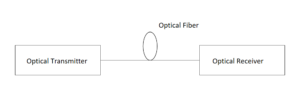
Schematic diagram of optical fiber communication system
The optical transmitter consists of a conversion device that converts an electrical signal with information into an optical signal and a transmission device that sends the optical signal into an optical fiber. The light source is its core device, which is composed of a laser diode LD. Optical fibers generally exist in the form of optical cables in practical systems. The optical receiver consists of a photodetector, an amplifier circuit, and a signal recovery circuit. A large number of active and passive devices are also included in the optical fiber communication system. Connectors are used to connect various devices and optical fibers, and optical couplers are used for occasions where optical splitting or combining needs to be transmitted. The optical amplifier plays the role of amplifying the light wave and is used to compensate for the weakening optical power caused by the attenuation of the optical fiber after the optical signal is transmitted for a certain distance.
Doped Fiber Amplifier
Amplifier
Optical amplifiers are devices that can directly amplify optical signals. After the optical signal transmits a certain distance along the optical fiber, it will be weakened due to the attenuation of the optical fiber, so the transmission distance is limited. In the early days of optical fiber communication, optical-electrical-optical regenerative repeaters were used to perform the photoelectric conversion, electric amplification, re-timed pulse shaping, and electro-optical conversion. In fiber-optic networks, when there are many optical transmitters sending light to multiple receivers at different bit rates and in different formats, traditional repeaters cannot be used, thus creating the need for optical amplifiers.
Compared with traditional repeaters, it has two distinct advantages:
- It can amplify the signal of any bit rate and format;
- It is not only for a single signal wavelength but can amplify several signals within a certain wavelength range.
How the amplifier works
The optical amplifier amplifies the incident light power based on the stimulated emission mechanism. The working principle is shown in Figure 2-1.
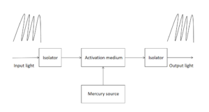
Figure 2-1 Working principle diagram of the optical amplifier
The active medium in the figure is a rare-earth-doped fiber, which absorbs the energy provided by the mercury source, makes the electrons jump to a high energy level, and produces a particle number inversion. The input signal photons pass through these activated electrons in the stimulated emission process, causing them to transition to lower energy levels, thereby producing an amplified signal.
Doped Fiber Amplifier
Doped fiber amplifiers take advantage of the gain mechanism caused by doping rare earth in optical fibers to achieve optical amplification. The most suitable doped fiber amplifiers for optical fiber communication systems are doped fiber amplifiers with an operating wavelength of 1550nm or 1300nm.
EDFA Structure
Erbium-doped fiber amplifier (EDFA) is a device that uses erbium-doped fiber as a gain medium and uses pump light from a laser diode to amplify signal light. The structure of the EDFA is shown in Figure 2-2.
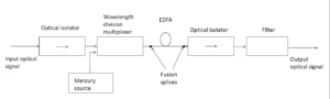
Structure of Erbium-Doped Fiber Amplifier
Erbium-doped fiber is the core component of EDFA. It uses silica fiber as the matrix, whose core is doped with the solid laser working substance – erbium. In the erbium-doped fiber of several meters to tens of meters, the interaction of light and matter is amplified and enhanced.
The mode field diameter of the erbium-doped fiber is 3-6μm, which is much shorter than the 9-16μm of the conventional fiber. This is to increase the energy density of the signal light and the pump light, thereby increasing the efficiency of their interaction. However, the reduction of the core diameter of the erbium-doped fiber also makes it mismatch the mode field of the conventional fiber, resulting in greater reflection and loss. The solution is to add a little fluorine to the fiber to reduce the refractive index and increase the mode field radius, to the extent that it can be matched with conventional fibers.
In order to achieve more efficient amplification, most of the erbium ions are concentrated in the central region of the core when making erbium-doped fibers. That is because, in the optical fiber, the optical field of the signal light and the pump light is approximately presented as Gaussian distribution– the light intensity is the strongest on the axis of the fiber core. The erbium ions in the paraxial region will make the light and matter fully interact, thereby improving energy conversion efficiency.
FiberMall’s EDFA
A typical EDFA mainly consists of the following parts:
- Pump source: Another core component of EDFA, it provides enough energy for optical signal amplification which is a necessary condition for realizing the population inversion of the gain medium. Since the pump source directly determines the performance of EDFA, it is required to be of high power, good stability, and long life. Practical EDFA pump sources are semiconductor laser diodes with two pump wavelengths: 980nm and 1480nm. The 980nm pump source is mostly used, which boasts low noise and high pump power.
- Wavelength division multiplexer: also known as a multiplexer(MUX), its function is to combine the pump light and signal light with wavelengths of 980/1550nm or 1480/1550nm and send it to the erbium-doped fiber. The requirements for it are small insertion loss and insensitivity to the polarization of light.
- Optical isolator: It makes the transmission unidirectional and prevents the reflection of light back to the original device, for this reflection will increase the noise of the amplifier and reduce the amplification efficiency.
- Optical filter: filters out the noise in the optical amplifier beyond the working bandwidth to improve the signal-to-noise ratio of the system.
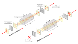
Faraday isolator allows the transmission of light in only one direction
Working Principle of the EDFA
The working mechanism of EDFA is based on stimulated radiation. In order to realize stimulated emission, it is necessary to generate a population inversion between energy level 2 and energy level 1, that is, a pump source is required to excite erbium ions from energy level 1 to energy level 2.
- Pump source with 980nm wavelength: the particles transition from energy level 1 to energy level 3, and stay at 1 μm for a short time. It falls to energy level 2 without radiation and stays at energy level 2 for 10μm, and the particles continue to enter energy level 2. Thus the number of particles in level 2 is much larger than that in energy level 1, which realizes the inversion of the number of particles in energy levels 1 and 2. The signal excites the erbium ions from energy level 2 back to energy level 1, and a small number of particles return to energy level 1 by spontaneous emission. They produce spontaneous emission noise, whose properties change and are amplified.
- Pump source with 1480nm wavelength: directly transitions erbium ions from energy level 1 to energy level 2 to achieve particle number inversion, and then from level 2 to 1 under input light excitation. The released light characteristics are the same as that of the input light and magnified.
EDFA Gain Flatness
The gain flatness refers to the relationship between gain and wavelength. The desired EDFA should have a relatively flat gain in the operating wavelength range we need, especially when used in the DWDM systems, it is required to have the same wavelength for all channels. gain. However, it is not easy to achieve the ideal gain flatness of erbium-doped fiber, the core component of EDFA.
In order to obtain a relatively flat gain characteristic and increase the bandwidth of the EDFA, there are two methods:
- Adopt a new type of broadband doped fiber;
- Place an equalization filter on the erbium-doped fiber link.
Wavelength Division Multiplexing Technology (WDM)
Although the current transmission rate of the technology combining single-wavelength optical carrier and traditional electrical time-division multiplexing (TDM) can reach the level of 40Gb/s, it is very difficult to further improve the transmission rate due to the limitation of the electron migration rate. Moreover, when the single-wavelength transmission wavelength is applied to the optical network, a new optical fiber route needs to be constructed. All of these limit the development and application of single-wavelength optical fiber transmission systems.
There are two methods to circumvent these limitations:
- UseDWDM technology to increase the transmission capacity of the optical fiber by increasing the number of channels transmitted in a single optical fiber;
- Adopt the OTDM(optical time-division multiplexing) technology to increase the single-channel transmission rate, thus achieving the purpose of increasing the communication capacity.
At present, the highest speed achieved by DWDM technology has reached 11Tb/s, and the highest speed of single-channel realized by OTDM technology in the laboratory has reached 640Gb/s.
The Working Principle of DWDM
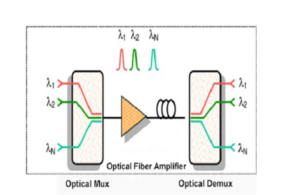
DWDM technology is a technology that uses light waves as carriers to transmit multiple optical carrier signals of different wavelengths in one optical fiber at the same time. Light waves of different wavelengths can carry voice, data, and image signals independently, so DWDM technology can double the transmission capacity of a single fiber. Figure 3-1 shows the working principle of the DWDM transmission system.
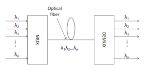
Figure 3-1 Working principle of the DWDM transmission system
At the sending end, n (numerous) optical transmitters work on n different wavelengths respectively. These n different wavelengths are separated by appropriate intervals, which are respectively recorded as λ1, λ2,…,λn, which are respectively modulated by signals as carriers to carry information. A wavelength division multiplexer combines these optical carrier signals of different wavelengths and couples them into a single-mode fiber. In the receiving part, a demultiplexer separates the optical carrier signals of different wavelengths and sends them to respective receivers for detection.
In the long-wavelength band, the optical fiber has two low-loss transmission windows, namely the 1310nm and 1550nm windows. The wavelength ranges of these two windows are 1270-1350 nm and 1480-1600 nm, corresponding to the spectral widths of 80 nm and 120 nm, respectively. However, for the high-quality 1550nm light source used in the current optical fiber communication system, the maximum output spectral line width after modulation does not exceed 0.2nm. Considering the wavelength drift caused by aging and temperature, it is reasonable to give a spectral width margin of about 0.41.6nm.
Basic Components of the DWDM System
The DWDM system must have lasers working on different wavelengths, multiplexers, and demultiplexers that can combine, select and split optical signals of different wavelengths. It also has the optical receiver for photoelectric detection of demultiplexed optical signals in order to restore the original signal. An amplifier that can simultaneously amplify various optical signals is also required to transmit long distances.
DWDM system should also have optical monitoring part and network management part.
DWDM system includes dual-fiber unidirectional transmission and single-fiber bidirectional transmission. Dual-fiber unidirectional transmission means that one fiber transmits in one direction, while the other fiber transmits in the opposite direction. Since the transmission in the two directions is completed by two optical fibers respectively, the same wavelength can be utilized in both directions at the same time. The single-fiber bidirectional transmission is to transmit in two directions by the same fiber, and the signals in the two directions must be assigned different wavelengths. The same wavelength cannot be used by signals in both directions at the same time.
Theoretical system diagram of the dwdm technology
Main features of the DWDM technology
- Make full use of the huge bandwidth resources of optical fiber to increase the transmission capacity of one optical fiber several times to dozens of times compared with single wavelength transmission, thereby increasing the transmission capacity of optical fiber and reducing cost, which has great application value and economic value.
- Since the wavelengths used in DWDM technology are independent of each other, it can transmit signals with completely different characteristics, complete the integration and separation of various signals, and realize the mixed transmission of multimedia signals.
- Since many communications are in full-duplex mode, DWDM technology can save a lot of line investment.
Optical amplifier in the DWDM system
In a DWDM system, when there are multiple wavelengths of signal transmission, the repeater will not work. It is necessary to demultiplex first, and then repeat the processing for each wavelength, which will result in a very large and complex repeater. This is an important problem that restricts the development of DWDM technology. So an erbium-doped fiber amplifier EDFA can be introduced. Since EDFA has a high gain in the bandwidth range of about 35nm near the low-loss transmission window of 1550nm of the fiber, it can simultaneously amplify multiple lightwave signals online to compensate for the weakening of the signal in the fiber, without the need for optical-to-electrical and electrical-to-optical conversion. Therefore, it solves the problem of multi-channel signal amplification in the DWDM system and replaces the repeater.
The following three points must be paid attention to when applying EDFA in the DWDM system:
- Gain flatness
When EDFA is only used to amplify the signal of one wavelength, it has good amplification characteristics. However, when multiple wavelengths enter the EDFA, some signals will have high gain while others will have low gain due to the uneven gain. When multiple EDFAs are cascaded, the power difference will be amplified, which not only leads to the different signal-to-noise ratio of each channel on the receiver but also may cause the signal power reaching the receiver to exceed the dynamic range of the receiver and cause the malfunction of the receiver.
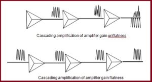
Cascading amplification of amplifier gain flatness or unflatness
Here are two ways to equalize this unevenness:
① Pre-equalization: The power of each channel is pre-set to different values at the optical transmitter end, and the power of the channel that will get high gain in the amplifier is set to low power, otherwise, it is set to high power.
②Add a well-designed filter to the EDFA module, so that its pass-band characteristic just compensates for the uneven gain of the amplifier, so as to achieve the purpose of flattening the amplifier gain.
One of the core components of this optical amplifier for DWDM is a filter that can flatten the gain of the amplifier. The filters used at this stage are mainly multilayer dielectric thin-film filters and fiber grating filters. The loss characteristics of such filters are usually fixed. In this way, when the EDFA is applied in the system, its gain flatness can only be guaranteed under certain operating conditions, and the gain is not flat under other conditions.
- Power transient and automatic gain control
In the actual system, when some channels suddenly fail or drop or add/drop at network nodes, the input power of the EDFA will suddenly increase/decrease, resulting in a transient change in the gain of the EDFA. The gain that other channels are obtained from the EDFA will decrease or increase, eventually resulting in a transient change in the power of those channels that remain on the fiber link reaching their respective receivers, which is called a power transient.
To prevent the occurrence of power transients, the gain of the amplifier must be controlled. Usually, there are three modes when EDFA works in a DWDM system: automatic gain control mode, automatic power control mode, and automatic current control mode. When working in automatic gain control mode, its gain is constant. If the input optical power changes, the control circuit can adjust the pumping current according to the required gain so that the EDFA still works at the specified gain point.
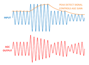
Automatic gain control
- ASE noise:
When the EDFA is cascaded, the ASE noise of the previous stage as a signal is input with the real signal to the next stage of EDFA and is amplified. The ASE noise accumulates, causing the degradation of the system’s signal-to-noise ratio. Therefore, when applied in a DWDM system, the noise figure of EDFA must be as small as possible.
Conclusion
This article introduces the structures, working principles, and applications of EDFA and DWDM technology. EDFA solves the problem of multi-channel signal amplification in the DWDM system. Thanks to the maturity and commercialization of EDFA technology, the DWDM technology develops rapidly and is applied. If there is deeper research on optical fiber communication, FiberMall will continue to publish articles to inform you.
Related Products:
-
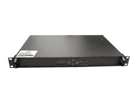
 EDFA 40/80 Channels DWDM C-Band Optical Pre-Amplifier Maximal Output Power +16dBm Gain 25dB Saturated Optical Power -9dBm
$1139.00
EDFA 40/80 Channels DWDM C-Band Optical Pre-Amplifier Maximal Output Power +16dBm Gain 25dB Saturated Optical Power -9dBm
$1139.00
-
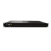
DCM 120km DCF-based Passive Dispersion Compensation Module, 11.5dB Low Loss, LC/UPC Connector
$1299.00
-
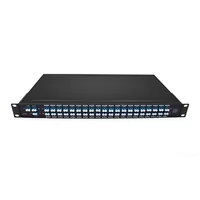
Low IL 3.5dB DWDM MUX DEMUX 40CH (C21-C60) LC/UPC Dual Fiber 1U Rack
$1200.00
-
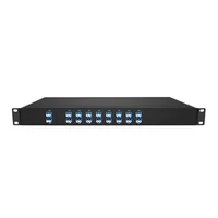
DWDM MUX DEMUX 16CH (C21-C36) with Monitor Port LC/UPC Dual Fiber 1U Rack
$800.00
-
Cisco DWDM-SFP10G-38.19 Compatible 10G DWDM SFP+ C49 100GHz 1538.19nm 80km LC SMF DDM Transceiver Module
$175.00
-
SFP-DW10G30-100C 10G DWDM SFP+ C30 100GHz 1553.32nm 100km LC SMF DDM Transceiver Module
$235.00
-
Cisco DWDM-SFP10G-C Compatible 10G DWDM Tunable SFP+ 50GHz 1529.55nm~1561.83nm 80km LC SMF DDM Transceiver Module
$750.00
-
Cisco DWDM-SFP25G-58.98 Compatible 25G DWDM SFP28 C23 100GHz 1558.98nm 10km LC SMF DDM Transceiver Module
$265.00
-
SFP28-DW25G20-20C 25G SFP28 DWDM C20 100GHz 20KM 1561.42nm LC SMF DDM Transceiver Module
$600.00
-
Cisco Compatible 100G DWDM QSFP28 C39 C40 100GHz CS DDM Optical Transceiver
$1600.00