The switch is the core equipment for monitoring network transmission. There are many critical technical parameters to consider when selecting switches. The hardware includes 100 megabit/gigabit / 10-gigabit rate ports, electrical/optical/ PoE port, port number, MAC address table depth, forwarding delay, cache size, VLAN, isolation, etc. Many projects have various problems due to improper switch selection, which seriously affects the delivery and experience of projects.
The following are aspects that need to be considered when selecting a switch:
Choose Gigabit or 100M?
In the network of the video surveillance system, a large amount of continuous video data needs to be transmitted, which requires the switch to have the ability to stably forward data. The more cameras connected to a switch, the greater the amount of data flowing through the switch. We can think of the code stream as the water flow, and the switches are the water conservancy junctions one by one. Once the flowing water flow exceeds the load, the dam will burst. Similarly, suppose the amount of data forwarded by the camera under the switch exceeds the forwarding capability of a specific port. In that case, it will also cause the port to discard a large amount of data and cause problems.
For example, a 100M switch forwarding data volume exceeding 100M will cause a large packet loss, resulting in a blurred screen and block.
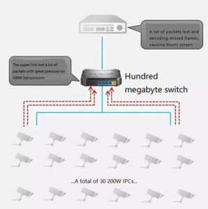
Overload of forwarded data volume causes packet loss
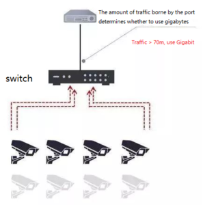
So, how many cameras do you need to choose gigabit switches?
We can choose according to the size of the camera uplink port forwarding data volume: if the forwarding data volume of the uplink port is greater than 70M, select gigabit port, that is, select gigabit switch or gigabit uplink switch.
A standard for choosing gigabit switches
Here is a quick calculation and selection method:
Bandwidth value = (sub-stream + main stream) * number of channels * 1.2
① Bandwidth value> 70M, use a gigabit switch
② Bandwidth value < 70M, use 100-megabyte switch
For example, if there is a switch with 20 H.264 200W cameras (4 + 1M) connected, then the forwarding rate of the uplink port is (4 + 1) * 20 * 1.2 = 120M > 70M, which requires a gigabit switch. In some scenarios, if the system structure cannot be optimized and the flow cannot be balanced, it needs to be equipped with a gigabit switch or a gigabit uplink switch.
Question 1: why multiply it by 1.2?
According to the principle of network communication, the encapsulation of data packets also follows the TCP / IP protocol. The data part needs to be marked with the header field of each protocol layer to smoothly transmit, so the header will also occupy a proportion of overhead.
The camera 4M bit rate or 2M bit rate we mention a lot refers to the size of the data part. According to the data communication ratio, the header overhead accounts for about 20%, so the formula should be multiplied by 1.2.
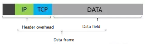
Data header accounts for about 20% of the overhead
Question 2: Why is it 70M not 100M?
The video data flow is composed of many frames, seemingly gentle data flow, and actually, a lot of instantaneous burst data will occur. This situation requires that the switch buffer and rectify the fluctuation of data.
The switch performs storage-forward-storage-forward on these data, so it is recommended to have a certain reservation. When designing a switching network, 30% to 40% of the reservation can be reserved. For a port of 100M, it is recommended that the forwarding traffic should not exceed 70M.
The cameras commonly used in engineering mainly include two bit rates: H.264 and H.265.
| Number of IPCs | Code rate | Total bandwidth | Switch |
|---|---|---|---|
| 4 | H.264 | 24M | 100M |
| H.265 | 12M | 100M | |
| 8 | H.264 | 48M | 100M |
| H.265 | 24M | 100M | |
| 12 | H.264 | 72M | Gigabit uplink switch |
| H.265 | 36M | 100M | |
| 16 | H.264 | 96M | Gigabit uplink or full Gigabit switch |
| H.265 | 48M | 100M | |
| 25 | H.264 | 150M | Gigabit uplink or full Gigabit switch |
| H.265 | 75M | Gigabit uplink switch | |
| 32 | H.264 | 192M | Gigabit uplink or full Gigabit switch |
| H.265 | 96M | Gigabit uplink or full Gigabit switch |
We use H.264 200W cameras (main and sub-streams are calculated as 4+1M) for example to illustrate bandwidth calculation and switch selection in common serial networks:
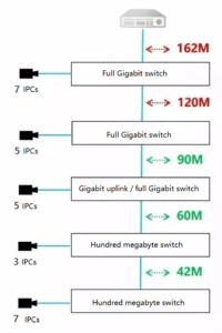
Bandwidth calculation and switch selection in common series networks
The network structure of star shape is as follows:
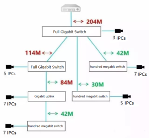
The network structure of star shape
How to choose a core switch?
Large and medium-sized monitoring networks are usually designed according to the access-aggregation-core structure. The core switch is the data forwarding center of the entire network and carries a large amount of data flow. Therefore, it is necessary to ensure that there is no bottleneck in the forwarding of each port of the core switch.
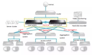
Structural Design of Monitoring Network
Some people have some misunderstandings about the choice of core switches. For example, let’s say that there are 200 and 500 cameras, if calculated as 500*5M=2500M, the result is far greater than the forwarding rate of gigabit ports. Must this kind of project use 10G switches?
Not necessarily. In fact, in a typical large-scale monitoring network, traffic will not be concentrated on one port, but will be distributed on multiple ports and forwarded by multiple gigabit ports.
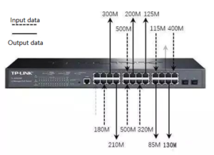
Traffic is forwarded by multiple gigabit ports
It can be seen that each port in the figure does not exceed 1000M, and 1000M bidirectional transmission can be achieved between any two gigabit ports of a full gigabit switch. The total throughput (full load) is generally less than or equal to the backplane bandwidth of the switch.
Therefore, it is recommended to select a core switch according to the number of IPCs:
①100~200 units of IPCs, Gigabit managed switches are recommended;
②200~500 units of IPCs, Layer 3 managed switches are recommended.
At present, Layer 2/3 managed full-gigabit switches are suitable for the core switch of the monitoring network, undertaking large-capacity data exchange, and building various networks.
③ For large or super large (300~1000) monitoring networks, it is necessary to use a layer 3 switch to divide the network segment.
The following is a list of networking solutions for 100, 300, and 500 points.
- Networking Scheme of 100 IPCs
There are about 100 points, and the design focuses on the non-blocking forwarding core.
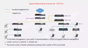
Networking Scheme of 100 IPCs
- Networking Scheme of 300 IPCs
With about 300 points, the design focuses on multiple network segments and smooth forwarding.
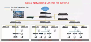
Networking Scheme of 300 IPCs
- Networking solutions of 500 IPCs
A redundant design is required, which is very suitable for large-scale parks such as government and enterprises.
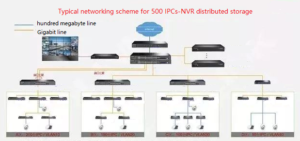
Networking Scheme of 500 IPCs
How to choose a PoE switch?
PoE is a technology for power supply and data transmission through a network cable. One network cable can be connected to a PoE camera point without additional power wiring.
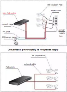
Traditional power supply vs PoE power supply
What should be considered when choosing a PoE switch?
- Single–port power
It is necessary to consider whether the power of a single port can meet the maximum power of any IPC attached to the switch, that is, select the specifications of the switch according to the maximum power of the IPC.
Ordinary PoE IPC power will not exceed 10W, so the switch only needs to support 802.3af. However, the power requirement of some high-speed domes is about 20W, or the power of some wireless access APs will be higher, then the switch needs to support 802.3at.
The following are the output power of the two technologies:
| Type | IEEE 802.3af | IEEE 802.3at |
|---|---|---|
| Maximum current | 350mA | 600mA |
| PSE output voltage | 44~ 57V DC | 50~57V DC |
| PSE output power | <= 15.4W | <=30W |
| PD input voltage | 36~ 57V DC | 42.5~57V DC |
| PD maximum power | 12.95W | 25.5W |
- The maximum power supply of the whole machine
Confirm that the maximum power supply power of the whole machine meets the requirements, and the power of all IPCs needs to be taken into account when designing. The maximum output power of the switch needs to be greater than the sum of the power of all IPCs.
- Type of power supply
There’s no need to consider this factor when using an eight-core network cable for transmission. If it is a four-core network cable, we need to confirm whether the switch supports a Class A power supply.
We can choose based on the advantages and costs of various PoEs:
| Standard | Standard PoE Class A | Standard PoE Class B | Non-standard PoE |
|---|---|---|---|
| Network cable requirements | Four cores | Eight cores | Eight cores |
| stability | stable | stable | unstable |
| Powered equipment | PoE equipment, non-PoE equipment plus splitter | PoE equipment, non-PoE equipment plus splitter | Both PoE devices and non-PoE devices need to add a splitter |
| electromagnetic interference | weak | weak | strong from a distance |
| common problems | no | 1. The four-core network cable cannot supply power, and the project needs to be re-wired. 2. The 4578 core of the eight-core network cable is of poor quality, and the impedance is too large to supply power over a long distance. | 1. It must be matched with a splitter, one-to-one, and the construction is complicated 2. The engineering installation is easy to exceed the IPC wide voltage range, and it is easy to burn out the camera. 3. The 4578 core of the eight-core network cable is of poor quality, and the impedance is too large to supply power for a long distance. |
| equipment cost | moderate | moderate | relatively low |
How to choose a fiber switch?
In the monitoring of long-distance points, fiber optic transceivers and fiber optic switches are often used. The following example includes a more comprehensive fiber optic switching network equipment, such as transceivers, switches, modules, and so on.
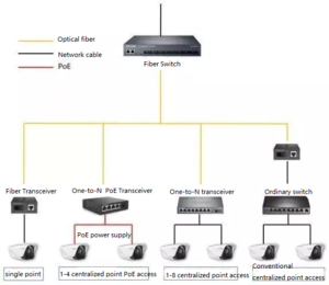
Equipment of optical fiber switching network
Optical switches, optical transceivers, and optical modules can be used with each other. It is necessary to use in pairs and make sure that the A-B ends match each other.
The A/B end is the two ends of the optical fiber transmission. No matter what the two ends are, they must be A and B to be paired for use (the product model is marked as the A end or the B end).
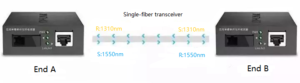
A / B ends need to be paired for fiber transmission
The working wavelengths of the A-end equipment are 1310nm (RX) and 1550nm (TX), which must be used with the B-end optical transceivers (RX1550nm, TX1310nm). Finally, factors such as the port speed, fiber type, dual fiber, or single fiber also need to be considered.
Related Products:
-
 SFP-GE35-BX10 1000Base BX BIDI SFP TX1310nm/RX1550nm 10km LC SMF DDM Transceiver Module
$6.00
SFP-GE35-BX10 1000Base BX BIDI SFP TX1310nm/RX1550nm 10km LC SMF DDM Transceiver Module
$6.00
-
SFP-GE53-BX10 1000Base BX BIDI SFP TX1550nm/RX1310nm 10km LC SMF DDM Transceiver Module
$9.00
-
SFP-GE35-BX20 1000Base BX BIDI SFP TX1310nm/RX1550nm 20km LC SMF DDM Transceiver Module
$6.00
-
SFP-GE53-BX20 1000Base BX BIDI SFP TX1550nm/RX1310nm 20km LC SMF DDM Transceiver Module
$9.00
-
SFP-GE35-BX40 1000Base BX BIDI SFP TX1310nm/RX1550nm 40km LC SMF DDM Transceiver Module
$15.00
-
SFP-GE53-BX40 1000Base BX BIDI SFP TX1550nm/RX1310nm 40km LC SMF DDM Transceiver Module
$15.00
-
SFP-GE45-BX80 1000Base BX BIDI SFP TX1490nm/RX1550nm 80km LC SMF DDM Transceiver Module
$30.00
-
SFP-GE54-BX80 1000Base BX BIDI SFP TX1550nm/RX1490nm 80km LC SMF DDM Transceiver Module
$30.00