In the 1980s, with the rise of computer and multimedia technology, increasingly people began to own computers and also began to use the network (LAN or Internet), so data communication services began to emerge and the demand for Internet access emerged. As optical fiber came into the picture as a new communication medium, the optical communication industry chain was increasingly taking shape. By the end of the 1980s, in order to apply optical fiber to broadband access services, PON (Passive Optical Network) technology began to emerge.
PON refers to the passive optical network. PON system should include an optical distribution network (ODN), optical line terminal (OLT), and optical network unit (ONU). Firstly, ODN is an FTTH (fiber to the home) optical network based on PON equipment, which provides an optical transmission channel between OLT and ONU. ODN does not contain any electronic components and electronic power supply. ODN is composed of passive components such as an optical splitter, so it does not need expensive active electronic equipment. A passive optical network (PON) consists of an OLT installed in the central control station and several ONUs installed in the user’s site. PON is the future development direction of the access network.
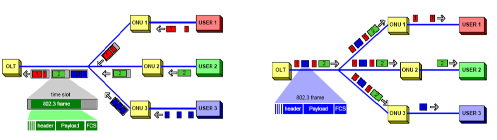
PON system block diagram
♦ Difference between dB and dBm
The attenuation of a light signal as it propagates along a fiber is an important consideration in the design of an optical communication system; the degree of attenuation plays a major role in determining the maximum transmission distance between a transmitter and a receiver or an in-line amplifier.
In communication engineering, the magnitude of power is usually expressed as a dBm value, which is a logarithmic measure and is defined as decibels relative to 1mW power level, that is, dBm represents decibels per milliwatt. It’s a dimensionless unit that actually specifies the power ratio rather than the exact power.
The formula for dBm is as follows:
dBm = 10 * log(P / 1mW), “P” represents the power in watts.
It should be mentioned here that dBm and dB are different, dB is defined as the difference in power or signal strength between any two given points.
The formula for dB is as follows:
dB = 10 log (P1 / P2), “P1” is the power intensity of the first point and P2 is the power intensity of the second point.
In summary, dBm is an absolute unit of measurement, and dB represents a relative number that indicates an increase or decrease in signal strength. DBm represents the absolute measure of signal strength at a given point (relative to 1mw). In addition, dB and dBm function differently in fiber optic networks: optical power is often measured in DBM, while optical fiber attenuation, loss, and insertion loss are expressed in dB.
♦ How to calculate the optical attenuation in a passive optical network(PON)?
In PON equipment, the maximum attenuation value of OLT is between 22-25dB, which means that the attenuation value cannot exceed 25 dB.
spec. of PLC Splitter Typical Value of Insertion Loss Maximum Deviation Range Between Ports Testing Instrument
1:2 50%-50% 3.4 dB 0.4 dB Optical Power Meter
1:2 5%-95% 11.8 dB : 0.6 dB 0.4 dB Optical Power Meter
1:2 10%-90% 10.4 dB : 0.9 dB 0.4 dB Optical Power Meter
1:2 20%-80% 7.4 dB : 1.3 dB 0.4 dB Optical Power Meter
1:2 30%-70% 5.6 dB : 1.9 dB 0.4 dB Optical Power Meter
1:2 40%-60% 4.4 dB : 2.6 dB 0.4 dB Optical Power Meter
1:4 equal division 7.2 dB 0.8 dB Optical Power Meter
1:8 equal division 10.7 dB 1.7 dB Optical Power Meter
1:16 equal division 14.8 dB 2.0 dB Optical Power Meter
1:32 equal division 17.8 dB 2.5 dB Optical Power Meter
1:2 PLC splitter attenuation is 3.01 dB
1:8 PLC splitter attenuation is 9.03 dB
1:16 PLC splitter attenuation is 12.04 dB
1:32 PLC splitter attenuation is 15.05 dB
1:64 PLC splitter attenuation is 18.06 dB
♦ How to choose optical modules and calculate optical power?
The passive optical network (PON) uses different optical modules to support different classes of ODN.
①The optical modules in use for EPON are as follows:
- 1000BASE-PX20, allowing channel insertion loss of 24dB, supporting a maximum optical split ratio of 1:32, new procurement equipment is no longer configured with EPON OLT PX20 optical modules.
- 1000BASE-PX20+, allowing channel insertion loss of 28dB, supporting a maximum optical split ratio of 1:64, the current procurement of EPON equipment is configured EPON OLT PX20+ optical modules.
②The optical modules in use for GPON are as follows:
- Class B +, the channel insertion loss is 28dB, and the maximum optical split ratio is 1:64. At present, GPON devices are generally equipped with GPON OLT class B + optical modules;
- Class C + , allows 32dB channel insertion loss and supports a maximum optical split ratio of 1:128. At present, GPON OLT class C + optical modules are mature and will soon be popularized.
- Class C + +, allows 32dB channel insertion loss and supports a maximum optical split ratio of 1:128. GPON OLT Class C + + optical module has not been widely used.
In the process of FTTH deployment, OLT, and ONU equipment shall adopt optical modules not lower than px20 + (EPON) and class C + (GPON) levels, and the attenuation of the optical cable link from the OLT end to the ONU end should be no more than 28dB.
③Calculate the optical power
Please refer to the following table:
PON Tech. Optical Module OLT ONU Obtained Power Prediction Optical channel cost Maximum Insertion Loss of PON
Emission power Worst receiving sensitivity Emission power Worst receiving sensitivity
MIN MAX MIN MAX Downlink Uplink Downlink Uplink Downlink Uplink
dBm dBm dBm dBm dBm dBm dB dB dB dB dB dB
EPON PX20 2 7 -27 -1 4 -24 26 26 2.5 2 23.5 24
PX20+ 2.5 7 -30 0 4 -27 29.5 30 1.5 2 28 28
GPON Class B+ 1.5 5 -28 0.5 5 -27 28.5 28.5 0.5 0.5 28 28
Class C+ 3 7 -32 0.5 5 -30 33 32.5 1 0.5 32 32
Note: The above index is the maximum insertion loss of the PON system calculated by taking the minimum value of the optical power emitted by the optical module using the principle of the worst value.
♦ How to calculate the transmission distance of a passive optical network (PON)?
Let’s take an example to see how to calculate the transmission distance of PON:
Step 1. The GPON network is adopted, and the optical module is class C + (the maximum insertion loss is 32dB).
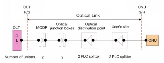
Step 2. According to the design of 1:128, the primary PLC splitter is 1:8 (insertion loss 10.5db), the secondary PLC splitter is 1:16 (insertion loss 13.8db), and the total insertion loss of the PLC splitter is 24.3db.
Step 3. The total insertion loss of the union is 0.5 × 4+0.25 × 4=3dB.
Step 4. The core of the trunk and distribution optical cable is G.652D, and the core of the lead-in optical cable is G.657A, without additional loss.
Step 5. It is calculated according to the attenuation coefficient (including fixed connection) of 0.4db/km in the uplink direction (1310nm).
Step 6. Line maintenance margin: 2.5dB.
Step 7. The final transmission distance will be: L ≤ (32-24.3-3-2.5) / 0.4 = 5.5 km.
Related Products:
-
 GPON-OLT-C+ GPON OLT SFP TX-2.5G/RX-1.25G TX-1490nm/RX-1310nm Class C+ 20km SC SMF DDM Transceiver Modules
$30.00
GPON-OLT-C+ GPON OLT SFP TX-2.5G/RX-1.25G TX-1490nm/RX-1310nm Class C+ 20km SC SMF DDM Transceiver Modules
$30.00
-
GPON-OLT-B+ GPON OLT SFP TX-2.5G/RX-1.25G TX-1490nm/RX-1310nm Class B+ 20km SC SMF DDM Transceiver Modules
$25.00
-
GPON-ONU-CLB+ GPON ONU SFP TX-1.25G/RX-2.5G TX-1310nm/RX-1490nm Class B+ 20km SC/UPC SMF DDM Transceiver Modules (Not GPON ONU STICK,NO MAC function)
$15.00
-
GPON-OLT-C++ GPON OLT SFP TX-2.5G/RX-1.25G TX-1490nm/RX-1310nm Class C++ 20km SC SMF DDM Transceiver Modules
$30.00
-
GPON-OLT-60C+ GPON OLT SFP TX-2.5G/RX-1.25G TX-1490nm/RX-1310nm Class C+ 60km SC SMF DDM Transceiver Modules
$38.00
-
EPON-OLT-PX20 EPON OLT SFP TX-1.25G/RX-1.25G TX-1490nm/RX-1310nm PX20 20km SC SMF DDM Transceiver Modules
$25.00
-
EPON-OLT-PX20+ EPON OLT SFP TX-1.25G/RX-1.25G TX-1490nm/RX-1310nm PX20+ 20km SC SMF DDM Transceiver Modules
$25.00
-
EPON-ONU-CLPX20+ EPON ONU SFP TX-1.25G/RX-1.25G TX-1310nm/RX-1490nm PX20+ 20km SC\UPC SMF DDM Transceiver Modules (Not EPON ONU STICK,NO MAC function)
$12.00
-
XGSPON-ONU-C XGSPON ONU SFP+ TX-9.95G/RX-9.95G TX-1270nm/RX-1577nm N1/N2 SC DDM 0°C~70°C Optical Transceivers
$75.00
-
FiberMall XGSPON-OLT-SN1 XGSPON OLT SFP+ TX-9.95G/RX-9.95G, 2.488G Tx-1577nm/Rx-1270nm SN1 SC UPC DDM Optical Transceivers
$300.00
-
FiberMall XGS/GPON-OLT-IB+ XGSPON GPON Combo B+ I-temp OLT MPM SFP-DD TX-9.95G/RX-9.95G Tx-1577nm/Rx-1270nm SC DDM -40°C~85°C Optical Transceivers
$315.00
-
FiberMall XGSPON-OLT-SN2 XGSPON OLT SFP+ TX-9.95G/RX-9.95G, 2.488G Tx-1577nm/Rx-1270nm SN2 SC UPC DDM Optical Transceivers
$315.00
-
FiberMall XGS/GPON-OLT-IC+ XGSPON GPON Combo C+ I-temp OLT MPM SFP-DD TX-9.95G/RX-9.95G Tx-1577nm/Rx-1270nm SC DDM Optical Transceivers
$330.00
-
NOKIA 3FE47581AD Compatible XGSPON GPON Combo B+ I-temp OLT MPM SFP-DD TX-9.95G/RX-9.95G Tx-1577nm/Rx-1270nm SC DDM -40°C~85°C Optical Transceivers
$315.00