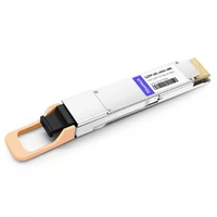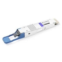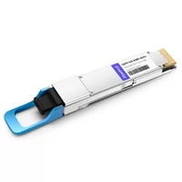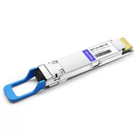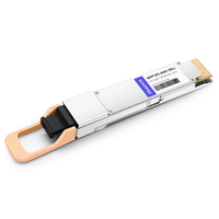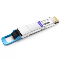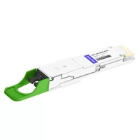

Chen Wei observed the monitoring dashboard until his frustration reached its peak. His 50 million dollar AI training cluster which contained 1024 advanced GPUs operated at 65 percent capacity. The system experienced performance problems because the 100G network system failed to provide sufficient data transfer speed. The GPUs experienced starvation.
After three months and a network upgrade his team installed 400G QSFP-DD infrastructure to replace the old switches. The team achieved 91 percent GPU usage after they completed their tasks. The system operated with identical hardware and software components while running the same tasks at increased data transfer speeds.

Data center operations experience situations which resemble Chen’s story at locations throughout the globe. The requirements of AI/ML workloads and cloud-scale applications and high-performance computing clusters exceed the capacity of 100G networks. The QSFP-DD transceiver has become the standard format for 400G and 800G connections because it delivers backward compatibility and high port density and future-proofing protection which most installations need.
The guide provides complete information required for successful QSFP-DD transceiver installation through its technical specifications and module selection and cable compatibility and pricing details and troubleshooting information.
What is a QSFP-DD Transceiver?
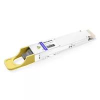
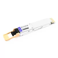
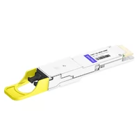
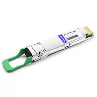
The QSFP-DD optical transceiver form factor enables 400G and 800G connections while supporting existing QSFP systems because it maintains backward compatibility with those systems.
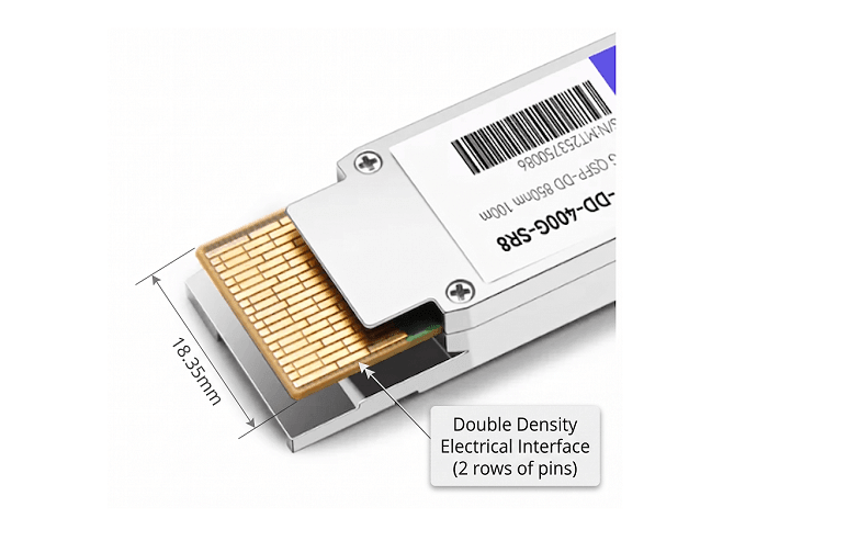
The “double density” designation refers to the electrical interface. The QSFP-DD system provides double the electrical lane capacity of QSFP28 which operates with 4 electrical lanes that transmit data at 25G to achieve a total of 100G. The clever part: QSFP-DD achieves this density increase while maintaining the same physical width as QSFP28—just 18.35 millimeters.
Key Innovation: Backward Compatibility
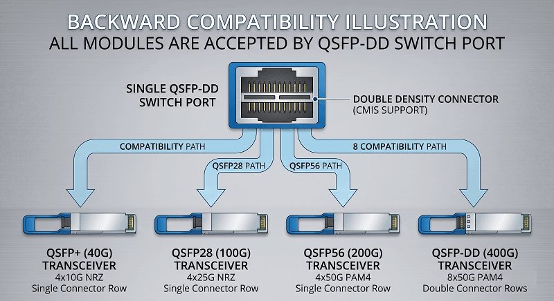
QSFP-DD’s defining advantage is its mechanical backward compatibility. A QSFP-DD port can accept:
- QSFP+ (40G) modules
- QSFP28 (100G) modules
- QSFP56 (200G) modules
- QSFP-DD (400G) modules
- QSFP-DD800 (800G) modules
The solution enables you to implement QSFP-DD switches while maintaining your current QSFP28 optical equipment and upgrading to 400G or 800G modules when your bandwidth needs increase. The solution allows you to keep your current system because it does not require complete equipment replacement and prevents any financial loss from unused assets.
The system has a major restriction because it permits only one-way compatibility. The design of QSFP-DD modules prevents them from being used with existing QSFP28 ports. The additional electrical pins and deeper form factor prevent this.
QSFP-DD MSA and Standards
The QSFP-DD form factor is governed by the QSFP-DD Multi-Source Agreement (MSA), a consortium of major networking vendors including Cisco, Broadcom, Juniper, and others. Key specifications include:
- SFF-8665: Mechanical specifications
- CMIS 4.0/5.0: Common Management Interface Specification for module management
- IEEE 802.3bs/cm/cu: Ethernet physical layer standards for 400G operation
This industry collaboration ensures interoperability between different vendors’ modules and switches—a critical requirement for data center operators who source equipment from multiple suppliers.
QSFP-DD vs Other Form Factors
Choosing the right transceiver form factor requires understanding the trade-offs between QSFP-DD and its primary alternatives.
QSFP28 vs QSFP-DD vs OSFP
| Specification | QSFP28 | QSFP-DD | OSFP |
| Max Speed | 100G | 400G/800G | 800G/1.6T |
| Electrical Lanes | 4×25G NRZ | 8×50G/100G PAM4 | 8×50G/100G/200G PAM4 |
| Width | 18.35mm | 18.35mm | 22.58mm |
| Height | 8.5mm | 8.5mm | 13.0mm |
| Backward Compatibility | QSFP+ | QSFP+/28/56 | None (requires adapter) |
| Integrated Heatsink | No | No | Yes (typical) |
| Power Capacity | ~6W | ~15W | ~25W |
| Port Density (1RU) | 36 ports | 36 ports | ~32 ports |
When to Choose QSFP-DD
Select QSFP-DD for these scenarios:
Mixed infrastructure environments: If you have existing QSFP28 modules and want to upgrade switches without replacing all optics immediately, QSFP-DD is your only option.
Maximum port density: QSFP-DD maintains the same 18.35mm width as QSFP28, enabling up to 36 ports in a 1RU switch. OSFP’s larger footprint typically reduces this to 32 ports.
Enterprise and cloud data centers: The balance of performance, compatibility, and density makes QSFP-DD ideal for general-purpose data center upgrades.
Gradual migration strategies: Backward compatibility allows phased upgrades—install switches now, upgrade optics later as budget and requirements dictate.
When to Consider OSFP
OSFP (Octal Small Form-factor Pluggable) may be preferable for:
AI/HPC clusters with dedicated infrastructure: If you’re building a new AI training cluster from scratch and don’t need backward compatibility, OSFP offers better thermal headroom for high-power coherent optics.
Maximum power applications: OSFP’s larger size and integrated heatsink support modules up to 25W, compared to QSFP-DD’s ~15W practical limit. This matters for 400G ZR+ coherent optics and future 1.6T modules.
Hyperscale greenfield deployments: Google, Meta, and other hyperscalers often choose OSFP for new builds where legacy compatibility isn’t a concern.
The Real-World Decision
Most organizations find QSFP-DD the practical choice. The backward compatibility alone justifies the selection—you’re not forced into a wholesale infrastructure replacement. Unless you have specific requirements that demand OSFP’s thermal advantages, QSFP-DD delivers the bandwidth you need with the flexibility to upgrade incrementally. For a detailed comparison, see our QSFP-DD vs OSFP guide.
QSFP-DD Transceiver Module Types and Specifications
QSFP-DD transceiver modules are categorized by reach and optical technology. Selecting the right type depends on your distance requirements, fiber infrastructure, and budget constraints.
400G Transceiver Module Types
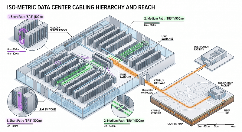
| Module Type | Reach | Fiber Type | Connector | Typical Power | Best For |
| SR8 | 100m (OM4) | Multimode | MPO-16 | 6–8W | In-rack, ToR-to-server |
| DR4 | 500m | Single-mode | MPO-12 APC | 8–10W | Spine-leaf, inter-rack |
| FR4 | 2km | Single-mode | Duplex LC | 8–12W | Campus, DCI |
| LR4 | 10km | Single-mode | Duplex LC | 12–15W | Metro, aggregation |
| ZR | 80–120km | Single-mode | Duplex LC | 15–20W | Long-haul DCI |
| ZR+ | 120km+ | Single-mode | Duplex LC | 18–25W | Extended reach |
Module Technology Deep-Dive
SR8 (Short Reach 8-lane)
SR8 uses 8 parallel VCSEL lasers at 850nm over multimode fiber. Each lane operates at 50G PAM4, providing 400G aggregate bandwidth. The MPO-16 connector handles all 8 transmit and 8 receive fibers in a single connection.
Use SR8 for:
- Top-of-Rack to server connections under 100 meters
- High-density in-rack cabling
- Environments with existing OM4/OM5 multimode infrastructure
Limitations: Cannot traverse single-mode fiber. Maximum reach of 100 meters on OM4 (70 meters on OM3).
DR4 (Direct Reach 4-lane)
Despite the name, DR4 actually uses 8 lanes for 400G—but they’re arranged as 4 pairs of 100G PAM4 signaling over single-mode fiber. The MPO-12 APC connector provides 4 fibers for transmit and 4 for receive.
Use DR4 for:
- Spine-leaf connections within the same data center (up to 500m)
- Cost-effective single-mode deployment
- Breakout applications (400G → 4×100G)
FR4 (Fiber Reach 4-lane)
FR4 uses CWDM4 (Coarse Wavelength Division Multiplexing) technology, combining 4 wavelengths (1271nm, 1291nm, 1311nm, 1331nm) over a single duplex LC fiber pair. Each wavelength carries 100G PAM4.
Use FR4 for:
- Campus connections up to 2km
- Data center interconnect between nearby facilities
- Cost-optimized medium-reach applications
LR4 (Long Reach 4-lane)
Similar to FR4 but with higher-power lasers and enhanced DSP for extended reach up to 10km. The technology is essentially the same—CWDM4 over duplex LC—but with optical components specified for longer distances.
Use LR4 for:
- Metro data center interconnect
- Cross-campus links
- Telecom aggregation applications
800G QSFP-DD Module Types
The transition to 800G doubles the per-lane rate from 50G to 100G PAM4 while maintaining the same 8-lane electrical interface.
| Module Type | Configuration | Reach | Connector |
| SR8 | 8×100G PAM4 | 100m | MPO-16 |
| 2×DR4 | Dual 400G DR4 | 500m | 2× MPO-12 |
| 2×FR4 | Dual 400G FR4 | 2km | 2× Duplex LC |
Key 800G consideration: QSFP-DD800 modules maintain the same physical form factor as 400G QSFP-DD, enabling upgrade paths without switch replacement. However, power consumption increases to 14–18W typical (up to 20W+ for some variants), requiring careful thermal planning.
QSFP-DD Transceiver Cable Compatibility
Cable selection significantly impacts deployment cost, power consumption, and signal integrity. QSFP-DD transceivers support three primary cable types for different reach requirements.
Passive Direct Attach Copper (DAC)
Reach: 1–3 meters
Power: <1.5W total (no active components)
Cost: Lowest ($50–150 per cable)
DAC cables use twinax copper wiring with no signal conditioning electronics. They’re the simplest, cheapest option for very short connections.
Best for:
- Same-rack Top-of-Rack switch connections
- Adjacent rack units in the same cabinet
- Cost-sensitive deployments
Limitations: Limited to 3 meters maximum. Heavier and less flexible than optical alternatives. No signal conditioning means higher susceptibility to interference.
Active Electrical Cable (AEC)
Reach: 1–7 meters
Power: ~9W total (QSFP-DD end: ~5W, breakout ends: ~1W each)
Cost: Mid-range ($150–400 per cable)
AECs include retimer and signal conditioning electronics within the cable assembly. This active circuitry cleans and regenerates the signal, extending reach beyond passive DAC limits.
Best for:
- ToR to spine connections within the same row
- AI clusters requiring signal integrity (NVIDIA-certified options available)
- Environments where optical cables are unnecessary
Active Optical Cable (AOC)
Reach: 1–30 meters (some models to 100m)
Power: ~10–12W (QSFP-DD end) + ~3.5W per breakout end
Cost: Highest ($300–800 per cable)
AOCs convert electrical signals to optical at the connector, transmitting over multimode fiber within the cable assembly. They’re thin, lightweight, and immune to electromagnetic interference.
Best for:
- Inter-rack spine-leaf connections
- Longer reach requirements (up to 30m standard, 100m extended)
- Environments with tight cable management constraints
Breakout Configurations
QSFP-DD enables flexible port utilization through breakout cables:
400G → 4×100G
The most common breakout, splitting 8×50G lanes into four 100G connections using 2 lanes each. Connects to QSFP28 ports for gradual 100G-to-400G migration.
400G → 2×200G
Splits 8×50G lanes into two 200G connections using 4 lanes each. Connects to QSFP56 ports.
800G → 2×400G
Splits 8×100G lanes into two 400G connections. Used for spine-to-spine aggregation or 800G-to-400G fan-out.
Critical breakout requirement: Method B (crossover) polarity is mandatory for MPO breakout cables. Incorrect polarity causes transmit-to-transmit or receive-to-receive connections that will not link.
400G Deployment with QSFP-DD
Deploying 400G QSFP-DD infrastructure requires understanding switch compatibility, power requirements, and migration strategies.
Switch Platform Compatibility
Cisco
- Nexus 9300-GX2 Series: 64× 400G QSFP-DD (2RU)
- Supports breakout: 400G → 4×100G or 2×200G
- Note: Cisco maintains strict compatibility policies; third-party MSA modules may trigger “unsupported” warnings without affecting operation
Arista
- 7060X6 Series: Full backward compatibility with QSFP+, QSFP28, QSFP56
- Enhanced Class 8 power support (up to 15W per port) for ZR optics
- External heatsink design runs warmer than OSFP alternatives
Juniper
- PTX10008: 36× 400G QSFP-DD line cards
- QFX10002-60C: Fixed-configuration data center switches
- Strong coherent optics support for DCI applications
NVIDIA/Mellanox
- Primary choice for InfiniBand NDR and AI Ethernet backends
- Spectrum-4 switches: 64× 800G QSFP-DD ports
- 800G ports backward compatible with 400G QSFP-DD modules
Power Class Requirements
QSFP-DD defines power classes that must be matched to switch capabilities:
| Power Class | Maximum Power | Typical Applications |
| Class 4 | 8.5W | Legacy modules |
| Class 6 | 10W | 400G SR8 |
| Class 7 | 12W | 400G DR4, FR4 |
| Class 8 | 15W+ | 400G ZR, 800G modules |
Critical: Verify your switch ports support the required power class before deploying high-power optics. A fully populated 32-port switch with Class 8 modules can draw 480W+ for optics alone—chassis power supplies must be sized accordingly.
Migration from 100G
The typical migration path leverages QSFP-DD’s backward compatibility:
- Phase 1: Install QSFP-DD switches, continue using existing QSFP28 modules
- Phase 2: Upgrade spine links to 400G QSFP-DD where bandwidth demands require
- Phase 3: Gradually upgrade ToR connections to 400G as server NICs transition
This phased approach spreads capital expenditure over multiple budget cycles while immediately gaining the switch platform benefits (buffer capacity, feature sets, future-proofing).
800G and Future Roadmap
While 400G is the current mainstream, 800G deployment is accelerating—particularly in AI/ML clusters where GPU interconnect bandwidth is critical.
QSFP-DD800 Specifications
QSFP-DD800 maintains the same 18.35mm width while increasing per-lane rates:
- Lanes: 8×100G PAM4 (vs. 8×50G for 400G)
- Aggregate: 800 Gbps
- Power: 14–18W typical, up to 20W for high-power variants
- Management: CMIS 5.0+
Key advantage: QSFP-DD800 modules fit into existing QSFP-DD cages. A switch deployed for 400G today can accept 800G modules tomorrow—assuming the switch ASIC supports 100G lane rates.
1.6T Roadmap (2025–2027)
The next evolution pushes per-lane rates to 200G PAM4:
- 2025: 1.6T QSFP-DD early samples (8×200G)
- 2026: Mainstream 1.6T deployment
- Power challenge: 1.6T modules may exceed QSFP-DD’s thermal capabilities, potentially requiring OSFP or new form factors
Emerging Alternatives
Linear Pluggable Optics (LPO)
LPO removes DSP chips from the module, reducing power by 4–10W. However, this requires host ASICs with specific signal conditioning support—limiting LPO to homogeneous deployments with compatible switch and module vendors.
Co-Packaged Optics (CPO)
CPO moves optical engines directly onto switch ASIC packages, eliminating the pluggable module entirely. This dramatically reduces power but eliminates field-serviceability. CPO is expected for 1.6T+ deployments in hyperscale environments.
QSFP-DD Transceiver Power and Thermal Considerations
Power consumption becomes a significant design factor at 400G and 800G densities.
Module Power by Type
| Module | Typical Power | 32-Port Switch Total |
| 400G SR8 | 6–8W | 192–256W |
| 400G DR4 | 8–10W | 256–320W |
| 400G FR4 | 8–12W | 256–384W |
| 400G LR4 | 12–15W | 384–480W |
| 400G ZR | 15–20W | 480–640W |
| 800G SR8 | 14–18W | 448–576W |

Thermal Design Implications
A 32-port 800G switch with fully populated SR8 modules generates over 500W of heat just from optics. Combined with switch ASIC power (300–500W), total chassis dissipation can exceed 1,000W.
Planning considerations:
- Front-to-back airflow: Standard for data centers, but verify cable management doesn’t obstruct exhaust
- Ambient temperature: QSFP-DD modules operate to 70°C case temperature, but sustained high temperatures reduce laser lifetime
- Finned-top modules: Some high-power variants include integrated heatsinks for better thermal transfer
Power Budget Calculation
When planning a QSFP-DD deployment, calculate total power draw:
Total Power = (Number of QSFP-DD modules × Module power) + Switch base power + Safety margin (20%)
For a 64-port 400G switch fully populated with FR4 modules:
- Optics power: 64 × 10W = 640W
- Switch base: ~400W
- Safety margin: 20% × 1,040W = 208W
- Total: ~1,250W
Ensure your rack power distribution and cooling can handle these loads before deployment.
QSFP-DD for AI and HPC
AI training clusters represent one of the fastest-growing applications for QSFP-DD, with unique requirements that differ from traditional data center traffic patterns.
GPU Interconnect Requirements
Modern AI training uses distributed computing across hundreds or thousands of GPUs. These GPUs must exchange gradient and activation data constantly during training—creating massive east-west traffic patterns.
Bandwidth requirements:
- NVIDIA H100: 400G per GPU (4th generation NVSwitch)
- NVIDIA H200: 400G per GPU
- Next-generation: 800G per GPU anticipated
A 1,024 GPU cluster requires over 400 Tb/s of network fabric capacity. QSFP-DD provides the density to build this fabric in a reasonable number of rack units.
Spine-Leaf for AI
AI clusters typically use two-tier spine-leaf architectures:
Leaf layer (Top-of-Rack)
- 32–48× 400G downlinks to GPU servers
- 8–16× 400G/800G uplinks to spine switches
- Uses SR8 for GPU connections (short reach within rack)
Spine layer
- 32–64× 800G ports connecting all leaf switches
- Full bisection bandwidth for all-to-all GPU communication
- Uses DR8 or FR8 for longer reach between rows
NVIDIA Compatibility
NVIDIA’s InfiniBand NDR and Spectrum Ethernet switches widely use QSFP-DD:
- InfiniBand NDR: 400G per port, QSFP-DD form factor
- Spectrum-4: 64× 800G QSFP-DD ports
- SHARP: In-network computing for collective operations
When building NVIDIA-certified clusters, verify specific cable and module compatibility—NVIDIA maintains strict qualification lists.
QSFP-DD Transceiver Pricing and TCO Analysis
Understanding QSFP-DD transceiver pricing helps build realistic budgets and evaluate the total cost of ownership.
Module Price Ranges (2025)
| Module Type | OEM List (Cisco) | Third-Party/MSA |
| 400G SR8 | ~$6,200 | 1,400–1,400–8,000 |
| 400G DR4 | ~5,200(new)/ 5,200(new)/ 3,100 (reman) | 2,850–2,850–12,000 |
| 400G FR4 | ~$6,700 | ~769–769–2,500 |
| 400G LR4 | ~$10,400 | ~925–925–3,500 |
| 400G ZR | ~$111,000 | 10,857–10,857–30,000 |
| 800G SR8 | ~8,000–8,000–12,000 | 3,500–3,500–10,000 |
Key observations:
- Third-party MSA-compliant modules typically cost 60–90% less than OEM list prices
- Volume discounts: Orders of 10,000+ units can achieve 30–40% off list pricing
- Remanufactured OEM modules offer ~40–60% savings with full warranty
Cable Costs
| Cable Type | 3m | 7m | 15m |
| DAC (400G) | $100–150 | N/A | N/A |
| AEC (400G) | $200–300 | $300–400 | N/A |
| AOC (400G) | $400–600 | $500–800 | $800–1,200 |
TCO Comparison: 100G vs 400G
Migrating from 100G to 400G delivers approximately 42% total cost of ownership reduction over three years:
| Factor | 100G Baseline | 400G QSFP-DD | Improvement |
| Cost per Gbps | 1.0× | 0.65× | 35% lower |
| Ports for 1 Tbps | 10 ports | 2.5 ports | 75% reduction |
| Switch count | 10× 100G | 1× 400G | 90% reduction |
| Power per Gbps | 0.045W | 0.025W | 44% savings |
| Fiber count | Higher | Lower | Simplified cabling |
The TCO advantage comes primarily from port consolidation—fewer switches, less fiber, reduced management overhead—rather than per-module price reductions alone.
QSFP-DD Transceiver Troubleshooting: Common Issues and Solutions
Even with proper planning, QSFP-DD transceiver deployments can encounter issues. Here’s how to diagnose and resolve the most common problems.
Issue 1: MPO Connector Contamination
Symptoms: Intermittent link flaps, high error rates, gradual signal degradation
Root cause: Dust, oil, or debris on MPO connector end-faces
Solution:
- Inspect with 400× fiber microscope
- Clean using wet-to-dry method with MPO-specific cleaning tools
- Verify APC polish angle (8 degrees) hasn’t been damaged
- Re-inspect before reconnecting
Prevention: Keep dust caps installed until immediate use. Clean before every insertion. For detailed procedures, see our MPO connector cleaning guide.
Issue 2: CMIS State Machine Hang
Symptoms: Module recognized but link won’t establish; stuck in “not ready” state
Root cause: Data-path initialization failure, often from firmware/CMIS version mismatch
Solution:
- Check switch logs for CMIS errors
- Verify module reaches “ModuleReady” state
- Confirm data-path reaches “DPActivated” state
- Update switch firmware to support module’s CMIS version
Issue 3: Power Class Insufficient
Symptoms: High-power modules (ZR, 800G) not recognized or randomly reset
Root cause: Switch port cannot supply required power (Class 8)
Solution:
- Verify switch supports required power class
- Check power budget hasn’t been exceeded by other ports
- Consider lower-power alternatives (FR4 vs ZR for shorter reach)
Issue 4: Breakout Configuration Mismatch
Symptoms: Some breakout ports work, others don’t; partial connectivity
Root cause: Incorrect lane mapping or polarity
Solution:
- Verify switch breakout configuration matches cable (4×100G vs 2×200G)
- Confirm Method B polarity for MPO breakout cables
- Check FEC mode consistency across all lanes
Diagnostic Commands
Most switches provide diagnostic visibility:
show interface transceiver eeprom # Module identification
show interface transceiver detail # Power, temperature, voltages
show interface transceiver ddm # Optical levels (TX/RX power)
Monitor these DDM parameters:
- TX power: Should be within vendor spec; degradation indicates laser aging
- RX power: Should be above receiver sensitivity with margin
- Temperature: Should be below 70°C case temperature
- Laser bias current: Increasing current over time indicates end-of-life
FAQ
What is a QSFP-DD transceiver?
The QSFP-DD transceiver serves as an optical module which provides 400G and 800G connectivity through its 8 electrical lanes that enable double the transmission capacity of QSFP28. The system provides multiple reach options which range from 100 meters (SR8) to more than 120 kilometers (ZR+) while maintaining compatibility with previous QSFP modules. See our complete guide to MPO fiber connectors for fiber infrastructure details.
What is a QSFP-DD transceiver used for?
QSFP-DD transceivers operate in data centers and AI/ML clusters and high-performance computing environments which demand 400G or 800G bandwidth. The technology is primarily used in spine-leaf switch connections, GPU interconnects, and data center interconnects (DCI).
Is QSFP-DD backward compatible with QSFP28?
The system enables one-way operation. Organizations can install QSFP-DD switches together with existing 100G optics through QSFP28 modules which QSFP-DD ports permit. Users cannot use QSFP-DD modules with legacy QSFP28 ports because the latter require additional electrical pins.
How much power does QSFP-DD use?
Devices operate between 6W and 20W power consumption for 400G SR8 and 400G ZR and 800G modules respectively. A fully populated 32-port switch can draw 250W to 640W for optics alone which requires organizations to plan their thermal management system.
QSFP-DD versus OSFP: which option should I select?
Select QSFP-DD when your existing QSFP28 system needs backward compatibility and you require the highest possible port density. Select OSFP when you build a new AI or HPC cluster that needs maximum thermal capacity and you do not require support for older systems.
What cable do I need for QSFP-DD breakout?
The active optical cable (AOC) and active electrical cable (AEC) should be used at 400G to 4×100G breakout when you have the correct breakout configuration. You must use Method B polarity for MPO connection purposes.
How do I troubleshoot QSFP-DD link failures?
Begin the process by inspecting physical components which includes cleaning MPO connectors and checking their proper installation and testing for bent pins. The system needs to show “ModuleReady” status according to CMIS state. The DDM system displays optical power levels through its readings. FEC mode and breakout configuration need verification on both ends to ensure they match.
Conclusion
The QSFP-DD transceiver has established itself as the dominant form factor for 400G and 800G data center connectivity. Its unique combination of backward compatibility, port density, and future-proofing makes it the practical choice for most organizations upgrading from 100G infrastructure.
Key takeaways for your deployment:
- Module selection: Match reach requirements to module type (SR8/DR4/FR4/LR4)
- Cable planning: Choose DAC for <3m, AEC for 3–7m, AOC for longer reaches
- Power planning: Calculate total power draw including optics (can exceed 500W per switch)
- Backward compatibility: Leverage QSFP-DD ports to accept existing QSFP28 modules during migration
- 800G readiness: QSFP-DD800 fits existing cages, enabling future upgrade paths
The transition to 400G and beyond isn’t just about speed—it’s about building infrastructure that can handle the AI/ML workloads, cloud-scale applications, and high-performance computing that define modern data centers. QSFP-DD provides the foundation for that infrastructure.
For assistance with QSFP-DD module selection, compatibility verification, or deployment planning, contact FiberMall’s technical team for expert guidance.
Sources:
- Ascent Optics AI Data Center Guide
- Ascent Optics Comprehensive QSFP-DD Guide
- Laser2000 QSFP-DD Comparison
- QSFPTEK 800G Guide
- Cisco GPL Pricing
- FiberCross Price Analysis
Related Products:
-
 QSFP-DD-400G-SR8 400G QSFP-DD SR8 PAM4 850nm 100m MTP/MPO OM3 FEC Optical Transceiver Module
$149.00
-
QSFP-DD-400G-DR4 400G QSFP-DD DR4 PAM4 1310nm 500m MTP/MPO SMF FEC Optical Transceiver Module
$400.00
-
QSFP-DD-400G-SR4 QSFP-DD 400G SR4 PAM4 850nm 100m MTP/MPO-12 OM4 FEC Optical Transceiver Module
$450.00
-
QSFP-DD-400G-FR4 400G QSFP-DD FR4 PAM4 CWDM4 2km LC SMF FEC Optical Transceiver Module
$500.00
-
QSFP-DD-400G-XDR4 400G QSFP-DD XDR4 PAM4 1310nm 2km MTP/MPO-12 SMF FEC Optical Transceiver Module
$550.00
-
QSFP-DD-400G-LR4 400G QSFP-DD LR4 PAM4 CWDM4 10km LC SMF FEC Optical Transceiver Module
$600.00
-
QSFP-DD-400G-SR4.2 400Gb/s QSFP-DD SR4 BiDi PAM4 850nm/910nm 100m/150m OM4/OM5 MMF MPO-12 FEC Optical Transceiver Module
$750.00
-
QSFP-DD-400G-PLR4 400G QSFP-DD PLR4 PAM4 1310nm 10km MTP/MPO-12 SMF FEC Optical Transceiver Module
$750.00
-
QSFP-DD-800G-DR8 800G-DR8 QSFP-DD PAM4 1310nm 500m DOM MTP/MPO-16 SMF Optical Transceiver Module
$1000.00
-
QSFP-DD-800G-SR8 800G SR8 QSFP-DD 850nm 100m OM4 MMF MPO-16 Optical Transceiver Module
$750.00
-
QSFP-DD-800G-DR8D QSFP-DD 8x100G DR PAM4 1310nm 500m DOM Dual MPO-12 SMF Optical Transceiver Module
$1000.00
-
QSFP-DD-800G-FR8L QSFP-DD 800G FR8 PAM4 CWDM8 2km DOM Duplex LC SMF Optical Transceiver Module
$3000.00
-
QSFP-DD-800G-2FR4L QSFP-DD 2x400G FR4 PAM4 CWDM4 2km DOM Dual duplex LC SMF Optical Transceiver Module
$1800.00
-
QSFP-DD-800G-FR8D QSFP-DD 8x100G FR/DR8+ PAM4 1310nm 2km DOM Dual MPO-12 SMF Optical Transceiver Module
$1300.00