Introduction
Evolution of Data Center Networking
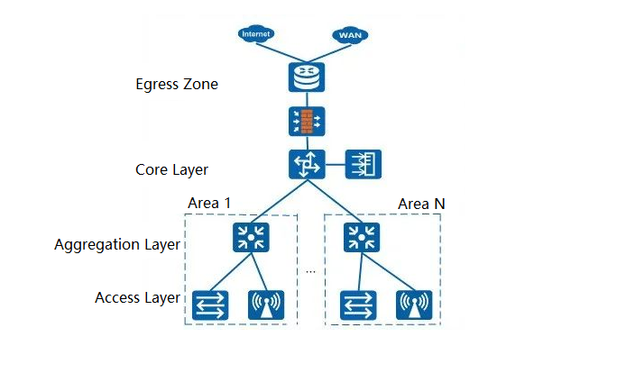
Over the past few decades, data center networking has undergone a massive transformation from simple local area networks to complex distributed systems. In the 1990s, data centers primarily relied on basic Layer 2 switching networks, where servers were interconnected via hubs or low-end switches. As the internet gained popularity, enterprises began demanding higher-performance networks, leading to the emergence of the traditional three-tier architecture (Core, Aggregation, Access).
This architecture clearly delineated functions while meeting the needs of small to medium-sized enterprise data centers at the time.
However, entering the 21st century, the rise of cloud computing, big data, and virtualization presented new challenges to networks. The traditional three-tier architecture gradually exposed issues like bandwidth bottlenecks, high latency, and limited scalability. For instance, in virtualized environments, east-west traffic between virtual machines surged, while the traditional architecture was better suited for north-south traffic, making it inefficient for new traffic patterns.
Thus, around 2010, the Spine-Leaf architecture began to gain prominence, becoming the standard for modern data centers due to its flattened design and high performance.
Rise of Spine-Leaf and Traditional Three-Tier Architectures
The Spine-Leaf architecture addresses the limitations of the traditional three-tier architecture in high-traffic environments by reducing network layers and optimizing data paths. Its design draws inspiration from the high connectivity of full-mesh networks but optimizes layers to reduce complexity and costs.
Additionally, the introduction of Software-Defined Networking (SDN) injects dynamic management and automation capabilities into Spine-Leaf, solidifying its dominance in modern data centers.
For example, cloud computing giants like Google and Amazon have widely adopted Spine-Leaf architecture in their data centers to support large-scale distributed computing and storage. In contrast, the traditional three-tier architecture remains suitable for small to medium-sized enterprises, but its limitations become increasingly apparent in high-load scenarios.
Detailed Explanation of Spine-Leaf Architecture
Definition and Structure of Spine-Leaf
Spine-Leaf architecture is a two-tier network topology that is simple yet powerful in design. It consists of the following two layers:
- Leaf Layer: Directly connects servers, storage devices, or other endpoints, handling data access and forwarding. Each Leaf switch typically features high-density ports (e.g., 48 x 10Gbps ports) and several uplink ports (e.g., 4 x 40Gbps ports).
- Spine Layer: Connects all Leaf switches, providing high-bandwidth, low-latency communication paths. Spine switches are usually high-performance devices focused on high-speed forwarding.
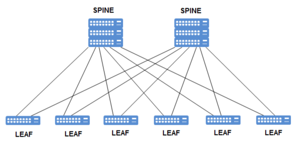
In Spine-Leaf architecture, every Leaf switch connects to all Spine switches, but Leaf switches do not connect directly to each other. This partial mesh design strikes a balance between performance and scalability. A simple analogy: The Spine layer acts like highway hubs, while the Leaf layer serves as city exits, enabling fast interconnections between all cities.
Layer 2 and Layer 3 Spine-Leaf Designs
Layer 2 Spine-Leaf:
- Features: Uses Layer 2 protocols (e.g., Ethernet) between Leaf and Spine layers, forwarding data via MAC addresses. Typically relies on Spanning Tree Protocol (STP) or MLAG technology to prevent loops.
- Applicable Scenarios: Small data centers or environments with extremely low latency requirements, such as low-latency trading systems.
- Example: A small data center deploys 4 Leaf switches and 2 Spine switches. Each Leaf connects to all Spine switches via 10Gbps links, forming a Layer 2 network supporting about 100 servers. MLAG (Multi-Link Aggregation) is used for redundancy.
- Advantages: Simple configuration, low latency (typically under 1ms).
- Limitations: High risk of broadcast storms, limited scalability (constrained by Layer 2 domain size).
Layer 3 Spine-Leaf:
- Features: Uses Layer 3 routing protocols (e.g., OSPF, BGP) between Leaf and Spine layers, forwarding data via IP addresses. Often employs ECMP (Equal-Cost Multi-Path routing) for load balancing.
- Applicable Scenarios: Large data centers requiring high scalability and network isolation, such as cloud computing environments.
- Example: A large data center deploys 16 Leaf switches and 4 Spine switches. Each Leaf connects to all Spine switches via 40Gbps links, using BGP routing, supporting about 1000 servers. ECMP ensures even traffic distribution across all Spine links.
- Advantages: High scalability, supports network segmentation (e.g., VXLAN segmentation).
- Limitations: Higher configuration complexity, requires familiarity with routing protocols.
Core Advantages and Features
- High Scalability: Easily expand the network by adding Leaf or Spine switches without redesigning. For example, adding a Leaf switch simply requires connecting it to all Spine switches.
- Low Latency: Flattened design reduces forwarding hops, with latency typically lower than traditional three-tier architectures. For instance, server-to-server communication requires only 2 hops (Leaf → Spine → Leaf).
- High Bandwidth: Multiple paths provide ample bandwidth for high-traffic scenarios. For example, 4 Spine switches can offer each Leaf a total uplink bandwidth of 160Gbps.
- High Redundancy: Multi-Spine design ensures network continuity even if some links or devices fail. For example, if one Spine switch goes down, others can still handle the traffic.
Examples: Small and Large Data Center Spine-Leaf Deployments
- Small Data Center: A startup company deployed a Spine-Leaf network with 4 Leaf switches and 2 Spine switches. Each Leaf connects to Spine switches via 10Gbps links, supporting 100 servers. The Layer 2 design uses MLAG technology, maintaining latency under 0.8ms. The company primarily runs web applications with low traffic demands, and the architecture meets initial expansion needs.
- Large Data Center: A cloud provider deployed a Layer 3 Spine-Leaf network with 32 Leaf switches and 8 Spine switches. Each Leaf connects to Spine switches via 100Gbps links, using BGP routing, supporting 5000 servers. This architecture supports large-scale virtualization (using VXLAN segmentation), improving network performance by 30% and reducing latency to 0.5ms.
Spine-Leaf vs. Traditional Three-Tier Architecture Comparison
Topology Structure Comparison
The following table compares the topology structures of the two architectures:
| Aspect | Traditional Three-Tier Architecture | Spine-Leaf Architecture |
| Structure | Tree-like: Access (leaves) → Aggregation (branches) → Core (trunk) | Grid-like: Data jumps between Leaves via shortest paths |
| Layers | Three layers (Core, Aggregation, Access) | Two layers (Spine, Leaf) |
| Connectivity | Hierarchical with potential bottlenecks | Partial mesh for balanced performance |
The traditional three-tier architecture resembles a tree, where data flows from leaves (Access) through branches (Aggregation) to the trunk (Core). In contrast, Spine-Leaf is like a grid, enabling shortest-path jumps between Leaves.
Performance and Latency Analysis
- Traditional Three-Tier Architecture: Data from Access to Core typically requires 3-4 hops, resulting in higher latency (about 2-5ms). The Aggregation layer can become a bottleneck, especially with surging east-west traffic. For example, virtual machine migrations may push Aggregation port utilization above 90%.
- Spine-Leaf: Data from Leaf to Spine needs only 1-2 hops, with low latency (about 0.5-1ms). Multi-Spine design provides ample bandwidth, avoiding bottlenecks. For instance, ECMP distributes traffic evenly across all Spine links.
Example: In a data center test, the traditional three-tier architecture had an average latency of 3.2ms and bandwidth utilization limited to 8Gbps during peaks. Spine-Leaf reduced latency to 0.8ms and boosted bandwidth to 40Gbps, achieving a 75% performance improvement.
Scalability and Management Complexity
- Traditional Three-Tier Architecture: Expansion requires adjusting Aggregation and Core configurations, involving complex link planning and protocol tweaks. For example, adding a new Access switch may necessitate reconfiguring uplink LACP (Link Aggregation Control Protocol). Management complexity rises significantly with scale.
- Spine-Leaf: Expansion is straightforward by adding Leaf or Spine switches. For example, adding a Leaf switch only requires connecting it to all Spine switches and updating BGP neighbors. Management complexity is low, with protocols like BGP simplifying large network oversight.
Data Center Case Study
Case: An e-commerce company originally used a three-tier architecture with 8 Access switches, 4 Aggregation switches, and 2 Core switches, supporting 1000 servers. Access layers used gigabit ports, and Aggregation connected to Core via 10Gbps links. As business grew, server count doubled to 2000, and traffic surged from 5Gbps to 20Gbps. Aggregation bandwidth shortages increased latency to 4ms, impacting database queries and page load speeds, degrading user experience.The company transitioned to Spine-Leaf with 16 Leaf switches and 4 Spine switches, using Layer 3 BGP routing. Each Leaf connected to Spine via 40Gbps links, boosting total bandwidth to 160Gbps. Post-transition, latency dropped to 0.9ms, bandwidth utilization rose by 40%, supporting higher concurrent traffic and significantly improving customer satisfaction.
Relationship Between Full-Mesh Networks and Spine-Leaf
Definition and Features of Full-Mesh Networks
A full-mesh network is a highly connected topology where every device directly links to all others. For example, in a 5-node full-mesh network, each node has 4 links, totaling 10 links.
Features: Offers the lowest latency (1 hop) and highest redundancy, but wiring and maintenance costs grow quadratically with device count (N*(N-1)/2 links).
Applicable Scenarios: Small high-performance networks, such as financial trading systems or small clusters.
Example: A trading firm deployed a 5-node full-mesh network with 10Gbps links per node. Latency was as low as 0.2ms, but wiring costs were high, and expanding to 6 nodes required 5 additional links, increasing complexity sharply.
Partial Mesh Design in Spine-Leaf
Connectivity: Each Leaf switch connects to all Spine switches, forming a partial mesh topology. Leaves do not connect directly, reducing wiring complexity. For example, 4 Leaves and 2 Spines require only 8 links, compared to 12 in full-mesh.
Advantages: Balances performance and cost, ideal for medium to large data centers.
Comparison and Connection Between Full-Mesh and Spine-Leaf
| Aspect | Full-Mesh Network | Spine-Leaf Architecture |
| Connectivity | Full interconnection (every device to every other) | Partial mesh (Leaves to all Spines) |
| Latency | Lowest (1 hop) | Low (1-2 hops) |
| Scalability | Poor (quadratic growth in links) | High (linear expansion) |
| Cost | High wiring and maintenance | Balanced cost |
Connection: Spine-Leaf borrows the high-connectivity concept from full-mesh but uses layering to reduce complexity. For instance, the Spine layer acts as a central hub, ensuring efficient Leaf communication while avoiding full-mesh overhead.Example: A financial firm’s small data center tried a full-mesh with 10 switches, requiring 9 links per switch and 45 total links—high wiring costs and maintenance challenges. Switching to Spine-Leaf (5 Leaves, 2 Spines) reduced links to 10, increased latency from 0.2ms to 0.6ms, but cut costs by 50% and enhanced scalability.
Synergistic Role of SDN in Spine-Leaf
Basic Principles of SDN
Software-Defined Networking (SDN) separates the network’s control plane from the data plane, enabling centralized management and dynamic configuration:
- Control Plane: Handled by an SDN controller (e.g., OpenFlow controller), managing network policies and traffic paths. It acts as the network’s “brain” for centralized decision-making.
- Data Plane: Executed by switches and routers for data forwarding. It serves as the network’s “arms” to carry out controller instructions.
For example, in traditional networks, each switch independently runs OSPF to calculate paths; in SDN, the controller computes and distributes routing tables centrally, simplifying device logic.
How SDN Enhances Spine-Leaf Architecture
Combining SDN with Spine-Leaf significantly boosts network flexibility and efficiency:
- Dynamic Traffic Optimization: The SDN controller monitors Spine-Leaf traffic in real-time, dynamically adjusting paths for load balancing. For example, if a Spine link is congested, the controller can reroute traffic to others.
- Automated Configuration: SDN allows quick deployment of VLANs, QoS policies, etc., reducing manual setup time. For instance, configuring VXLAN for 100 Leaf switches takes just minutes.
- Rapid Fault Recovery: Upon detecting a Spine or Leaf failure, SDN automatically switches to backup paths. For example, if a Spine goes down, the controller reallocates traffic in seconds.
Practical Applications of SDN in Data Centers
Case: A cloud service provider integrated an SDN controller into its Spine-Leaf data center for automated traffic management. The setup included 32 Leaves and 8 Spines, supporting 5000 servers. During a traffic peak, one Spine link hit 90% utilization; SDN dynamically redistributed traffic, preventing congestion and improving performance by 25%. Network configuration time also shrank from hours to minutes, accelerating new service deployments.
Future of Spine-Leaf and Recommendations
Future Trends in Data Center Networking
With the rapid advancement of cloud computing, AI, and 5G, data center networks will demand higher performance and flexibility:
- Intelligence: AI-driven network management will predict traffic patterns and optimize performance. For example, AI can adjust Spine-Leaf load balancing based on historical data.
- High Bandwidth: 400Gbps or even 800Gbps links will become standard for Spine-Leaf. For instance, vendors launched 800Gbps Spine switches in 2023.
- Deep Integration: Spine-Leaf will fuse more tightly with SDN and NFV (Network Function Virtualization). For example, NFV can virtualize firewall functions at the Leaf layer.
Integration of Spine-Leaf with Emerging Technologies
Future Spine-Leaf architectures will incorporate more cutting-edge technologies:
- AI Optimization: Machine learning to predict network faults and preemptively adjust paths. For example, AI can foresee Spine switch overload risks and divert traffic in advance.
- Zero-Trust Security: Combined with SDN for dynamic security policies to protect data centers. For instance, each Leaf switch can verify traffic sources in real-time based on SDN directives.
Summary
Spine-Leaf architecture, with its flattened, high-performance, and highly scalable features, has replaced the traditional Core-Aggregation-Access architecture as the cornerstone of modern data centers. By optimizing the high-connectivity ideas from full-mesh networks and leveraging SDN’s dynamic management capabilities, it demonstrates immense advantages in performance, flexibility, and management efficiency.
Related Products:
-
 QSFP-DD-400G-SR8 400G QSFP-DD SR8 PAM4 850nm 100m MTP/MPO OM3 FEC Optical Transceiver Module
$149.00
QSFP-DD-400G-SR8 400G QSFP-DD SR8 PAM4 850nm 100m MTP/MPO OM3 FEC Optical Transceiver Module
$149.00
-
QSFP-DD-400G-DR4 400G QSFP-DD DR4 PAM4 1310nm 500m MTP/MPO SMF FEC Optical Transceiver Module
$400.00
-
QSFP-DD-400G-SR4 QSFP-DD 400G SR4 PAM4 850nm 100m MTP/MPO-12 OM4 FEC Optical Transceiver Module
$450.00
-
QSFP-DD-400G-FR4 400G QSFP-DD FR4 PAM4 CWDM4 2km LC SMF FEC Optical Transceiver Module
$500.00
-
QSFP-DD-400G-XDR4 400G QSFP-DD XDR4 PAM4 1310nm 2km MTP/MPO-12 SMF FEC Optical Transceiver Module
$580.00
-
QSFP-DD-400G-LR4 400G QSFP-DD LR4 PAM4 CWDM4 10km LC SMF FEC Optical Transceiver Module
$600.00
-
QDD-4X100G-FR-Si QSFP-DD 4 x100G FR PAM4 1310nm 2km MTP/MPO-12 SMF FEC CMIS3.0 Silicon photonics Optical Transceiver Module
$650.00
-
QDD-4X100G-FR-4Si QSFP-DD 4 x 100G FR PAM4 1310nm 2km MTP/MPO-12 SMF FEC CMIS4.0 Silicon photonics Optical Transceiver Module
$750.00
-
QSFP-DD-400G-SR4.2 400Gb/s QSFP-DD SR4 BiDi PAM4 850nm/910nm 100m/150m OM4/OM5 MMF MPO-12 FEC Optical Transceiver Module
$900.00
-
Arista Q112-400G-SR4 Compatible 400G QSFP112 SR4 PAM4 850nm 100m MTP/MPO-12 OM3 FEC Optical Transceiver Module
$450.00
-
Cisco Q112-400G-DR4 Compatible 400G NDR QSFP112 DR4 PAM4 1310nm 500m MPO-12 with FEC Optical Transceiver Module
$850.00
-
OSFP-800G-DR8D-FLT 800G-DR8 OSFP Flat Top PAM4 1310nm 500m DOM Dual MTP/MPO-12 SMF Optical Transceiver Module
$1199.00
-
OSFP-800G-SR8D-FLT OSFP 8x100G SR8 Flat Top PAM4 850nm 100m DOM Dual MPO-12 MMF Optical Transceiver Module
$650.00
-
OSFP-800G-SR8D OSFP 8x100G SR8 PAM4 850nm 100m DOM Dual MPO-12 MMF Optical Transceiver Module
$650.00
-
OSFP-800G-DR8D 800G-DR8 OSFP PAM4 1310nm 500m DOM Dual MTP/MPO-12 SMF Optical Transceiver Module
$850.00
-
OSFP-800G-2FR4L OSFP 2x400G FR4 PAM4 1310nm 2km DOM Dual Duplex LC SMF Optical Transceiver Module
$1200.00