

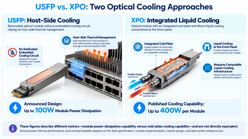
The USFP thermal design is intended to support up to 100W of power dissipation per module without a dedicated embedded cooling circuit. In a host-cooled implementation, heat can be transferred from the module through a thermal interface material (TIM) to a host-side heat sink, which may use chassis airflow or liquid cooling. The final thermal interface and cooling implementation will depend on the finalized specification and host platform design.
That’s a bigger deal than it sounds. Cooling has rarely been the headline when a new optical form factor launches. NVIDIA and Cisco announced plans for USFP, the Ultra-Dense Small Form Factor Pluggable, at the OCP Global Summit on October 12, 2026. Designed for 400 Gb/s-per-lane electrical signaling, USFP aims to increase bandwidth density while preserving the serviceability of pluggable optics. How the final design manages heat will be an important consideration for next-generation AI-fabric data centers.
You already know that higher speed per lane can increase the thermal demands on an optical module. What makes USFP notable is its architectural direction: eliminate the need for a dedicated embedded cooling circuit within the removable module, leaving the host platform responsible for managing the thermal load.
What Is the USFP Thermal Design?
USFP’s announced design supports up to 100W of power dissipation per module without requiring a separate, dedicated embedded cooling circuit inside the transceiver. The precise thermal interface and host-side cooling implementation will depend on the finalized specification and the system design.
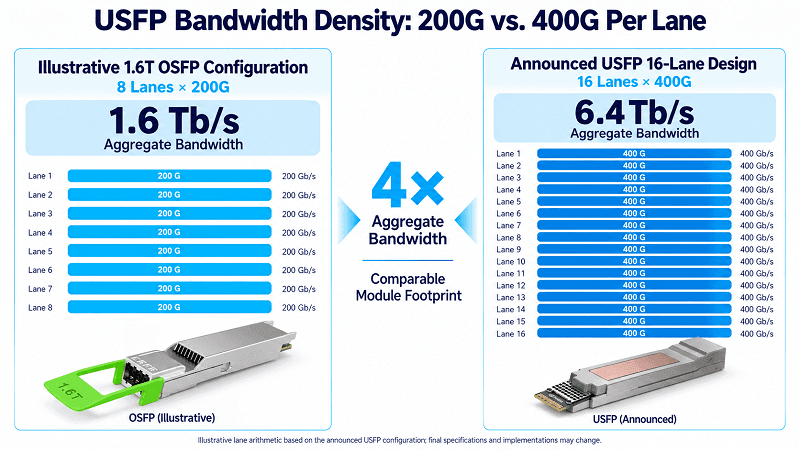
USFP is designed to be the first pluggable optical form factor supporting 400 Gb/s-per-lane electrical signaling. Its first planned modules use 16 full-duplex lanes in an OSFP-sized footprint, providing 6.4 Tb/s of aggregate capacity. The architecture can scale to 32 lanes and 12.8 Tb/s in future implementations.
The thermal design is an important part of this announcement. According to the official NVIDIA and Cisco announcement, USFP is designed to dissipate up to 100W without a dedicated embedded cooling circuit. This is a stated design capability, not a measurement of typical module power consumption or a guarantee that every implementation will operate at 100W.
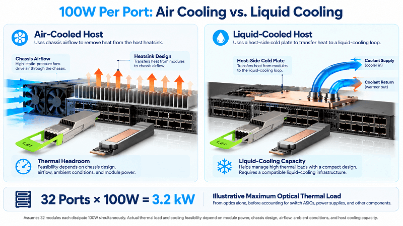
In a host-cooled implementation, the module case could transfer heat through a thermal interface material (TIM) to a host-side heat sink. Depending on the switch design, the heat sink could reject heat through chassis airflow or transfer it to a liquid-cooled cold plate. The exact contact geometry, interface resistance, mounting pressure, and cooling requirements will need to be validated against the final specification and platform design.
If you’re evaluating optical module thermal management for 400G or 800G modules in a live data center, the distinction between module-level and host-level cooling is important. FiberMall’s networking engineers can help you evaluate the trade-offs for your chassis, airflow, and rack power budget.
Why 100W? The Thermal Cost of 400G Per Lane
The 100W figure represents a design envelope for high-density pluggable optics. It cannot be derived from lane rate and lane count alone. However, USFP’s planned architecture illustrates why thermal management becomes increasingly important as bandwidth scales within a similar physical footprint.
SerDes and DSP Power at 400 Gb/s Per Lane
The host ASIC’s serializer/deserializer (SerDes), together with the module’s optical and signal-conditioning circuitry, contributes to the overall power consumption of a high-speed link. Depending on the optical architecture, a module may also incorporate retiming or digital signal processing (DSP). Equalization, clocking, signal conditioning, and other functions can add to the thermal load.
Moving from 200G to 400G per electrical lane increases signaling demands and can raise power consumption. However, the actual power required depends on the implementation, including the optical technology, transmission distance, signal-processing architecture, and host platform.
USFP is an announced form-factor initiative designed around 400G-per-lane electrical signaling. Existing platforms, including Cisco’s G300/G302 generation and NVIDIA’s Spectrum-X networking ecosystem, provide context for the industry’s transition toward higher-density AI networking. USFP’s deployment timeline will depend on the availability of compatible host silicon, qualified modules, and the finalized specification.
Where the Watts Go: 16 Lanes into 6.4T
The lane calculations illustrate USFP’s bandwidth-density objective. USFP’s planned 16 lanes at 400G per lane provide 6.4 Tb/s of aggregate capacity. By comparison, a 1.6T OSFP implementation using eight 200G lanes provides 1.6 Tb/s.
That represents four times the aggregate bandwidth in a comparable module footprint, assuming the announced lane configurations.
The efficiency story is important but easy to misinterpret. NVIDIA and Cisco state that USFP is designed to deliver approximately 1.3 times the power efficiency of 200G-per-lane pluggable optics, alongside four times the bandwidth density. These are published design claims rather than independently verified production measurements.
Power efficiency and absolute power consumption are different metrics. A module can deliver more bandwidth while consuming more total power, even if its energy consumption per bit improves. The actual power draw will depend on the final module implementation and operating conditions. The 100W figure should therefore be treated as the announced power-dissipation capability, not as a value directly calculated from the lane count.
The USFP Heat Path: From Module to Host Heatsink
Understanding the thermal design means following heat from the module to the system-level cooling solution. Three considerations are central to the announced architecture.
No Embedded Cooling Loop: Why the Coolant Stays in the Switch
The central design decision is that USFP does not require a dedicated embedded cooling circuit inside the transceiver. This can reduce cooling-system complexity at the module level and avoid the need for coolant connections on each removable module.
Why does that matter? Because pluggable modules are regularly inserted, removed, reseated, and replaced by technicians. A module with its own liquid-cooling circuit may require additional fluid connections, sealing mechanisms, and service procedures. Keeping the cooling circuit on the host side can simplify module replacement and reduce the number of coolant interfaces handled during routine maintenance.
The actual reliability benefits will depend on the final mechanical design and the host platform. Nevertheless, avoiding a dedicated cooling circuit within the removable module is a meaningful architectural choice for high-power pluggable optics.
Thermal Interface Material to the Host Heat Sink
In a host-cooled implementation, a possible heat-transfer path runs from the laser and DSP junctions, through the module package and case, across a thermal interface material (TIM), and into the host heat sink. From there, the heat may be rejected into chassis airflow or transferred to a liquid-cooling loop through a cold plate.
The TIM is an important part of this thermal path. Its thermal resistance, contact pressure, surface flatness, and material conductivity can all affect heat transfer. At high module power levels, the complete thermal path must be evaluated rather than treating the interface material in isolation.
These are established thermal-engineering considerations, but the specific interface design and allowable thermal resistance for USFP will require validation against the finalized mechanical specification and host implementation.
No Mating Coolant Plugs on the Removable Module
A host-side liquid-cooling implementation could transfer heat through a TIM to a cold plate without requiring coolant couplings on the removable USFP module.
That distinction matters for serviceability. If the liquid circuit remains entirely on the host side, technicians can remove the module without disconnecting coolant fittings attached to the module itself. This can simplify routine replacement procedures and reduce the need for module-level fluid handling.
The precise maintenance process will still depend on the host’s mechanical and thermal design. Avoiding dedicated module-level coolant connections, however, helps preserve the familiar service model of pluggable optics.
Air Cooling vs. Liquid Cooling at 100W Per Port
A 100W thermal design target for a single module is only part of the system-level picture. The cumulative load across a fully populated switch is the more important planning consideration.
A hypothetical 32-port switch with every module dissipating 100W would have up to 3.2 kW of heat associated with the optics alone, before accounting for the switch ASICs, power supplies, and other components. This is an upper-bound sizing illustration, not a prediction of typical module power consumption.
Such a thermal load can exceed the cooling capacity of many conventional 1U air-cooled systems. However, there is no universal air-cooling limit that applies to every chassis. Feasibility depends on the chassis design, fan performance, airflow path, inlet temperature, heat-sink design, module occupancy, and the host manufacturer’s thermal limits.
For air-cooled data halls, high-static-pressure fans, improved heat-sink designs, and carefully managed airflow may be necessary. Operators may also need to reduce the number of populated high-power ports if the system cannot dissipate the full thermal load within its operating limits.
For liquid-cooled facilities, a host-side cold plate may provide an alternative way to manage concentrated thermal loads. Because USFP is designed without a dedicated embedded cooling circuit, a host-side cooling solution could avoid the need for coolant couplings on every removable module. The suitability of either approach must be established through system-level thermal validation.
USFP vs XPO: Two Philosophies of Optical Cooling
A useful comparison is USFP’s announced approach and XPO, the liquid-cooled optical form factor introduced by Arista Networks.
XPO takes a different approach by integrating a liquid cold plate into the module. In its official XPO announcement, Arista states that the integrated cold plate is capable of cooling up to 400W per module. This is a stated cooling capability, not necessarily the typical electrical power consumed by every XPO implementation.
The trade-off is the cooling infrastructure and service model. An XPO deployment requires a compatible liquid-cooling arrangement at the front panel, with the associated plumbing and service procedures. The precise implementation will determine the coolant connections, maintenance requirements, and leak-management measures.
USFP takes a different direction, specifying up to 100W of power dissipation without a dedicated embedded cooling circuit in the module. This approach aims to preserve the operational familiarity of pluggable optics while leaving thermal management to the host platform.
The two designs therefore emphasize different priorities. USFP focuses on avoiding a dedicated module-level cooling circuit, while XPO integrates a cold plate designed for a higher cooling load. The published 100W USFP figure and 400W XPO figure describe different aspects of their announced designs and should not be treated as directly equivalent measurements.
For the full form-factor comparison, see our USFP vs XPO vs OSFP-XD comparison.
| Form Factor | Power or Thermal Reference | Cooling Approach | Module-Integrated Cooling | Serviceability Considerations |
| QSFP-DD (400G) | Approximately 14–20W, depending on module design | Typically air-cooled | None | Conventional pull-and-replace operation |
| 1.6T OSFP | Approximately 30–40W, depending on implementation | Air cooling or platform-specific liquid cooling | Varies by implementation | Conventional pull-and-replace operation |
| USFP | Up to 100W power dissipation, as announced | Host-side air or liquid cooling, depending on platform | No dedicated embedded cooling circuit | Designed to avoid dedicated coolant connections on the removable module |
| XPO | Integrated cold plate designed to cool up to 400W per module | Liquid cooling at the front panel | Integrated cold plate | Requires a compatible liquid-cooling and service arrangement |
Note: The QSFP-DD and OSFP figures are approximate industry references, not universal specifications. USFP’s 100W figure refers to its announced power-dissipation capability, whereas XPO’s 400W figure refers to the stated cooling capability of its integrated cold plate. These metrics should not be compared as though they represent identical measurements. Verify all product-specific figures against current vendor documentation before making deployment decisions.
Explore FiberMall’s 400G and 800G optical transceiver solutions for AI-fabric interconnects, or request a quote to match module selection and cooling requirements to your rack power budget.
How USFP Thermal Design Fits the Wider Cooling Landscape
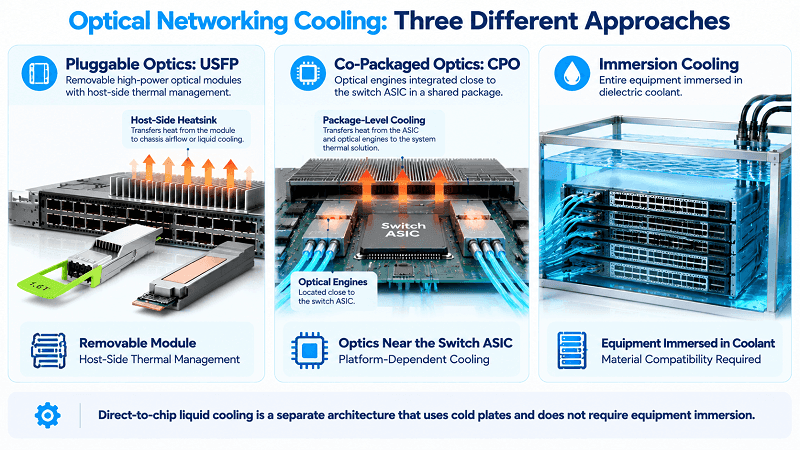
USFP is not the only approach to thermal management in next-generation optical networking. It sits within a broader range of architectures, each with different implications for cooling, packaging, and serviceability.
Co-packaged optics (CPO) places optical engines close to or within the same package as a switch ASIC, reducing reliance on conventional front-panel pluggable optics for those links. Thermal management takes place at the package and system levels, and the cooling solution depends on the platform design. Liquid-cooled implementations may use cold plates or other thermal assemblies to remove heat from the switch package and associated components.
Unlike front-panel pluggable optics, CPO can change how optical components are accessed and serviced. The exact maintenance model depends on the implementation. USFP, by contrast, is designed to retain a removable module format, although its practical serviceability will also depend on the finalized specification and host platform.
At another point in the cooling landscape, FiberMall’s immersion-compatible AOC cables address interconnect requirements in immersion-cooled environments. These applications should be distinguished from direct-to-chip liquid cooling, in which coolant circulates through cold plates or similar components rather than immersing the equipment in a tank.
Where USFP addresses module-level thermal management at the switch interface, immersion-compatible interconnects address cable and material requirements in a liquid environment. Suitability for immersion cooling depends on the compatibility of cable jackets, connector materials, and other components with the particular coolant and operating conditions.
The common thread is that increasing AI-fabric power density is putting more pressure on every layer of the network, from optical modules to cables, chassis, and facility cooling. USFP’s stated contribution is a path toward higher-bandwidth pluggable optics without requiring a dedicated embedded cooling circuit within each removable module.
For more on the architectural differences, see our USFP vs CPO comparison.
What the USFP 100W Envelope Means for Data Center Planning
If you are planning around USFP, three questions should guide your evaluation.
1. What is your rack power budget?
At up to 100W of module power dissipation, a fully populated high-density switch could create a substantial thermal load. Liquid-cooled host platforms may provide additional cooling headroom, while the feasibility of air cooling depends on the specific chassis and operating conditions.
2. Is the deployment brownfield or greenfield?
Existing air-cooled facilities may value an architecture that avoids dedicated coolant connections on each removable module. However, the host platform must still be able to dissipate the module’s heat within its operating limits. Greenfield liquid-cooled deployments may also evaluate XPO when higher per-module cooling capability is a priority and the required infrastructure is available.
3. How often do you replace optical modules?
If field serviceability is important, avoiding a dedicated embedded cooling circuit can simplify the design of removable modules. However, the actual maintenance benefits will depend on the final mechanical interface, host cooling arrangement, and service procedures.
One important caveat before committing to a roadmap: USFP remains an announced form-factor initiative rather than a finalized public specification or shipping product. NVIDIA and Cisco have announced plans to develop an open industry specification through a community-led multi-source project. A public sampling or availability date was not specified in the announcement, so the latest official updates should be checked before making procurement commitments.
The 100W power-dissipation capability, four-times bandwidth-density figure, and approximately 1.3-times power-efficiency figure are published design claims, not independently verified production results. Final specifications, product availability, and measured performance may change as the standard and compatible silicon mature.
Conclusion
USFP’s thermal design represents a specific architectural direction: support up to 100W of power dissipation per module without requiring a dedicated embedded cooling circuit inside the removable transceiver. A host-cooled implementation may transfer heat through a TIM to a host-side heat sink, with air or liquid cooling selected according to the system design.
The intended benefit is a path toward 400G-per-lane electrical signaling and 6.4 Tb/s of aggregate capacity in the first planned 16-lane configuration, with a potential roadmap to 12.8 Tb/s. The design aims to preserve the serviceability of pluggable optics while avoiding dedicated coolant connections on each removable module. Achieving that goal will depend on the final thermal interface, host cooling capacity, and qualified platform implementations.
For data center architects, the decision comes down to rack power budgets, available cooling infrastructure, module serviceability, and the maturity of the relevant ecosystem. USFP may be attractive when avoiding module-level coolant connections is a priority and the host platform can handle the thermal load. XPO may be worth evaluating when integrated liquid cooling and higher per-module cooling capability are central requirements.
Both approaches require careful validation against final specifications, actual module power consumption, and system-level thermal limits before deployment.