We use mobile phones and computers to post on Facebook and watch videos every day. These simple daily activities require the support of a large-capacity transportation system. Otherwise, the contents of Facebook and videos cannot be accurately delivered to your mobile phone or computer monitor. In this large-capacity transportation system, a significant technology is WDM/OTN.

Contents on the Internet
WDM (Wavelength Division Multiplexing) is a technology that uses different light waves to carry different services and transmits multiple services simultaneously in the same fiber. OTN (Optical Transport Network) can be seen as an optimized and upgraded version of WDM. Let’s talk about these two technologies below.
What is WDM?
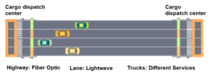
If the optical fiber is likened to a highway, the light waves used to transmit services in the WDM system are compared to trucks. Different transmission services such as Facebook and videos are equivalent to packages to be transported, which are directly placed on different trucks. If these trucks all swarm in the optical fiber transmission regardless of lanes, it will cause chaos and disorder in the entire expressway, affecting the transmission efficiency. With WDM, different transmission services can be transmitted simultaneously on the same optical fiber, which is equivalent to dividing lanes for different vehicles on the highway, allowing different cars to run on different lanes at the same time, improving transmission efficiency.
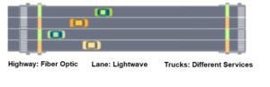
Simulation diagram of optical fiber
At the same time, to ensure smooth traffic, it is necessary to distinguish lanes so that different vehicles can go their own way. Similar to the division of large lanes and small lanes on highways, the lanes in the WDM system are divided into two types: CWDM (Coarse Wavelength Division Multiplexing) and DWDM (Dense Wavelength Division Multiplexing). The former has a larger lane interval (wavelength interval), generally, 20 nm, while the latter interval is small, generally less than 0.8 nm.
What does a WDM system consist of?
Does WDM allow different services to be transmitted on one fiber at the same time as long as the lanes are divided? Things are not that simple, let’s take a look at how WDM does it!
In professional terms, a WDM system is generally composed of an OTU (Optical Transponder Unit), a MUX/DEMUX unit, a monitoring channel, and an optical amplifier unit.
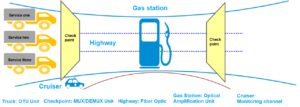
Simulation diagram of the WDM system
Then, how do the various parts of WDM work together to complete service transmission? Let’s take a look at the transmission process of services in WDM.
- For services to be transmitted in WDM, it is first necessary to send the services to WDM’s dedicated vehicle (i.e.OTU unit), and convert these service signals into standard wavelength optical signals recognized by WDM.
- The standard wave optical signal vehicles carrying the services, drive to the checkpoint (i.e. the multiplexing unit) and are arranged to different lanes through the checkpoint. Each vehicle runs on one lane of the highway at the same time.
- The driving status of the vehicle needs to be supervised by the cruiser, that is, the monitoring channel, to ensure normal service transmission.
- If the transportation distance is long, it is also necessary to let the vehicle enter the same gas station, that is, to regenerate and amplify the service signal through the optical amplifier unit to ensure that the service is not damaged during long-distance transportation.
- When the service is transported to the terminal station, the vehicle will come out from the inspection station (i.e. the demultiplexing unit) and be diverted to the corresponding exit of the receiving customer terminal. The service is unloaded from the vehicle, that is, converted into a customer service signal (i.e. a service signal without wavelength information) through the OTU unit, and sent to the customer.
What is OTN?
From the above introduction, we can conclude that the biggest advantage of WDM technology is that it makes good use of the resources of optical fibers and can provide large-capacity data transmission. However, WDM also has the following disadvantages:
- If the service”package” on the WDM vehicle has an error during transportation, there is no way to identify it. That is, the WDM system has a weak ability to monitor, manage, operate and maintain services.
- If a service is transmitted on the designated channel of the WDM system, the channel cannot be used by other services, which will cause a waste of resources. It’s like the lane of each vehicle is fixed on the highway, even if the lane is free, other types of vehicles cannot use this lane.
With the development of communication networks, the amount of data on the data network has increased rapidly, and experts have to continue to develop the potential of WDM and improve its capabilities of WDM, so a new technology was born – OTN.
As mentioned earlier, the WDM system is similar to the highway traffic system, and the OTN is its upgraded version. Its upgraded functions are mainly reflected in the following two aspects:
- Add operation and maintenance rules. The specific measures are to increase the frame structure to improve the monitoring, management, and operation and maintenance capabilities of the service.
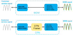
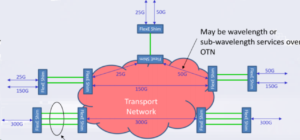
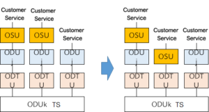
The comparison diagram of the WDM and OTN system
From the simplified WDM and OTN system comparison diagram above, it can be seen that:
In the WDM system, the service without wavelength information entering the WDM system is merely converted into service with wavelength information, and placed in the system for transmission. That is to say, the WDM system has no monitoring mechanism for the transmitted services, and only ensures that the services can be transmitted to the receiving end.
In the OTN system, a set of rules for putting services into the OTN system is provided, that is, the so-called frame structure requirements. The services entering the OTN system will be packaged according to the OTN frame structure requirements, that is, adding monitoring, management, operation, and maintenance information. And then the services are converted into ones with wavelength information and sent to the OTN system for transmission.
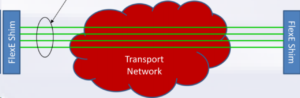
- An electrical crossover function is added so that the OTN system can process customer service signals and WDM signals respectively.
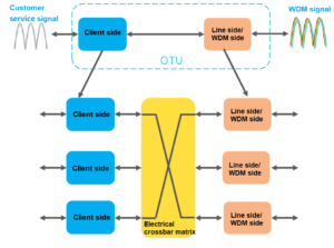
The electrical crossover function
As mentioned above, the customer service signals need to be converted into wavelength division signals for the WDM system to transmit customer services. When the traditional WDM system processes this function, it is directly implemented through the same single board, and each customer service needs to occupy one lightwave carrier. When there are more and more types of customer services on the network, in order to transmit these services in the WDM system, it is necessary to develop new boards to carry these services, which will increase the cost of network construction;
On the other hand, these services will also occupy more light waves, resulting in resource shortages. Therefore, the OTN system introduces an electrical crossover function, which is like adding a cargo dispatch center to the traditional WDM transportation system. The cargo dispatch center will package and dispatch different goods (i.e different services) entering the OTN transportation system into different vehicles (i.e. carry them with different light waves).
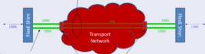
the Cargo Dispatch Center
The advantage of the cargo dispatch center is that if new customer service is added to the network, only the customer-side single card that accesses the new service needs to be added. And the existing single card transport service on the line side is borrowed, which saves the cost of network construction. Meanwhile, when the trucks in a certain lane are idle, the cargo dispatch center can load the trucks with customer services at any time, so as to avoid the trucks running empty on the lane and wasting resources.
To sum up, OTN is an optimization of WDM, which further improves the operation and maintenance capabilities and flexible resource scheduling capabilities of WDM systems.
In a word, WDM/OTN technology acts as a large-capacity transportation system of data networks nowadays. It continuously transmits these “goods” of information data with higher reliability, higher flexible scheduling capability, and higher resource utilization rate.
Next, we will discuss the progress and evolution trend of OTN technology.
400G technology
Several major manufacturers have participated in and completed 400 G-related tests. The test environment includes G.652D and G.654E optical fibers, and networks using EDFA and Raman amplifiers. The test pattern is 400G 16QAM, the B2B OSNR tolerance has been achieved below 17db, and the baud rate is around 91.
| Channel rate | Modulation format | Baud rate (Gbaud) | Expected interval (GHz) |
|---|---|---|---|
| 400G | 64QAM | 39.09 | 50 |
| PCS16QAM | 68 | 75 | |
| PCS16QAM | 85 | 100 | |
| PCS16QAM | 91.6 | 100 | |
| 400G | PCS16QAM | 120 | 137.5 |
| 16QAM | 59.03 | 75 | |
| QPSK | 119.08 |
400G related tests
400G 16QAM is limited by transmission distance and is not practical for backbone long-distance networks. Therefore, manufacturers are encouraged to demonstrate 400G QPSK. Some manufacturers have supported or will realize the commercial use of 400G QPSK by the end of this year. In terms of the frequency band, the C++ band has been commercialized on a large scale, and the future deployment proposal of C+L is being considered.
800G technology
The related research on 800G technology was started a few years ago, and some manufacturers have already completed the laboratory verification test of 800G 64QAM, and have already supported the commercial deployment of 800G. While other manufacturers are making efforts on 1.2T.
| Channel rate | Modulation format | Baud rate (Gbaud) | Expected interval (GHz) |
|---|---|---|---|
| 800G | 64QAM | 78.18 | 87.5 |
| PCS64QAM | 95 | 112.5 | |
| PCS64QAM | 91.6 | 100 | |
| 16QAM | 118.06 |
800G related tests
Meanwhile, due to 800G applications, it’s very likely that C+L cannot meet the 80-wave transmission requirements. Related research on the S-band has begun.
FlexE technology
FlexE services are accessed as customer services. The standard mapping and multiplexing methods that support 50G/100G/200G FlexE services to OTUk(V) are as follows:
- Method one: Unaware method
The 50G/100G/200G PHY in the FlexE Group is mapped to the OPUFlex through the BMP, then to the ODU4 channel signal, and finally to the OTU4(V)/OTUCn line interface. The Deskew processing method can be used to reduce the delay difference of each Ethernet channel.
Method one: Unaware method
- Method two: Termination
The Idle Mapping Procedure (IMP) is used to realize the mapping from the client signal to the ODUFlex, which matches the rate difference between the client signal and the ODUflex container by adding or deleting the Idle code in the FlexE client signal.
Method two: Termination
The transmission network does not perceive FlexE sub-services and treats them as n*100GE/200GE/400GE for mapping/de-mapping.
- Method three: Perception
By removing the unused time slots and multiplexing the partially filled FlexE signals, they are mapped to OPUflex through BGMP, to ODTU4.ts/ODTUCn.ts through GMP. Then they are multiplexed to ODU4/Cn channel signals, and finally to the OTU4(V)/OTUCn line interface.
Method three: Perception
OSU technology
- VC is carried on OSU
Different VCs in the SDH interface are mapped to different OSU pipes according to the service attribution. Service scheduling is flexible and bandwidth utilization is high. They can be mapped by single or multiple VCns to one OSU, and VC<>OSU processing node is achieved by clock synchronization.
Different VCs are mapped to different OSU pipes
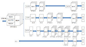
It is required that this solution supports the recovery of the VC from the STM-N interface and maps it to the OSU pipeline, and performs end-to-end scheduling transmission. Service granules support mapping of VC12, VC3, and VC4 service granules to OSU. It is divided into the following two scenarios.
Scenario 1: A single VCn (VC4/VC3/VC12) is mapped to a single OSU.
(1) The VC signal is first mapped to AU/TU;
(2) The AU/TU is mapped to the OSU in a manner similar to CBR, and the PTR pointer points to the starting position of the AU/TU.
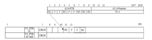
A single VCn (VC4/VC3/VC12) is mapped to a single OSU
Scenario 2: Multiple VCn (VC4/VC3/VC12) are mapped to a single OSU.
(1) Map the M-channel VC to the M-channel aligned AU/TU, and then map it to the OSU by byte interleaving;
(2) The AU/TU is mapped to the OSU in a manner similar to CBR, and the PTR pointer points to the starting position of the first AU/TU.
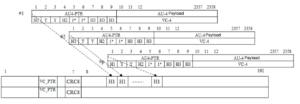
Multiple VCn (VC4/VC3/VC12) are mapped to a single OSU
- OSU supports GCC function with the channel
Traditional OTN GCC can be used for ASON recovery, as well as automatic discovery and port verification. It can be used for decoupling and transfer of controlled information. Based on the OTN standard system, each layer requires GCC due to the completeness of the path layer functions. Hence OSU also needs its own GCC construction layer network to establish OSU subnet connections.
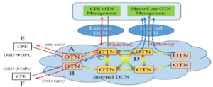
OSU supports GCC function with the channel
Based on OSU GCC recovery, cooperating with each OSU channel to build an associated communication channel, OSU-based rerouting can be implemented. GCC binding can be owned and high-quality service signaling can be prioritized.
- OSU and ODU mixed transmission function
The current OSU supports a two-step multiplexing scheme, which imposes some restrictions on network bandwidth planning. Operators are not flexible enough to design the network, which leads to the problem of time slot bandwidth fragmentation.
In the future, ODTU can support mixed multiplexing of OSU and ODU. It also supports flexible time slot allocation to realize bandwidth sharing and flexible bandwidth planning.
ODTU can support mixed multiplexing of OSU and ODU
Optical layer technology
Optical layer OAM technology is at the transmitting end of the optoelectronic fusion cross-connect device. The output end of each OTU is loaded with a low-frequency top modulation signal. For service signals of different wavelengths, the frequencies of the top-tuning signals are different and correspond to the wavelengths one-to-one. Overhead information loading is implemented synchronously.
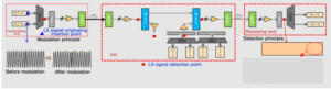
One-point modulation, Multi-point detection
At the same time, the detection of the top modulation signal can be realized, and it can be detected at each subsequent detection point. The optical layer technology can also detect the overhead information of the channel and various key characteristic information of each wavelength.
Related Products:
-
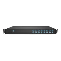
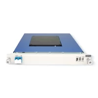
 Passive CWDM Double Fiber Mux & Demux Module 16 CH (1310-1610nm) 1U Rack
$570.00
Passive CWDM Double Fiber Mux & Demux Module 16 CH (1310-1610nm) 1U Rack
$570.00
-
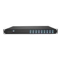
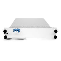
Passive CWDM Double Fiber Mux & Demux Module 18 CH (1270-1610nm) LC/UPC 1U Rack
$630.00
-
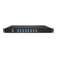
DWDM MUX DEMUX 16CH (CXX-CXX) with Monitor Port LC/UPC Dual Fiber 1U Rack
$800.00
-
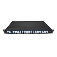
Low IL 3.5dB DWDM MUX DEMUX 40CH (C21-C60) LC/UPC Dual Fiber 1U Rack
$1200.00
-
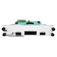
200G Transponder/Muxponder : 2x 100G QSFP28 to 1x 200G CFP2 DP-8QAM or DP-16QAM
$4550.00
-
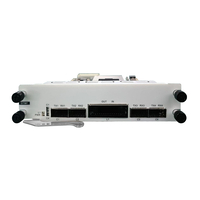
400G Transponder/Muxponder : 4x 100G QSFP28 to 1x 400G CFP2 DP-16QAM and 200G DP-16QAM
$5000.00
-
EDFA 40/80 Channels C-Band Optical Amplifier Maximal Output Power +16dBm Gain 25dB Saturated Optical Power -9dBm
$1200.00
-
80km DCF-based Passive Dispersion Compensation Module, 8.7dB Low Loss, LC/UPC
$1100.00