The use of analog signals to transmit digital information has effectively increased the data transmission rate. With serial data rates hitting 56 Gbps per channel and beyond, signal impairments caused by increased bandwidth have prompted the high-speed serial data industry to adopt PAM4. However, this signal-encoding scheme also faces a series of testing challenges in practical application. This technology brief outline outlines the differences between NRZ and PAM4 modulation and analyses some challenges and corresponding techniques in PAM4 signal testing.
What are PAM4 and NRZ Signals?
NRZ(Non-Return-to-Zero), also known as Pulse Amplitude Modulation 2-Level (PAM2) is a traditional digital signal coding scheme. This modulation technique has two voltage levels to represent logic 0 and logic 1. Each signal symbol period can transmit 1 bit of logical information. Whereas, the PAM signal can use more voltage signal levels so that each signal symbol period can transmit more bits of logic information. For instance, the PAM4 signal uses 4 different signal levels for data transmission, and each symbol period can represent 2 bits of logic information (0, 1, 2, 3). The following figure shows the waveform difference between a typical NRZ signal and the PAM4 signal.
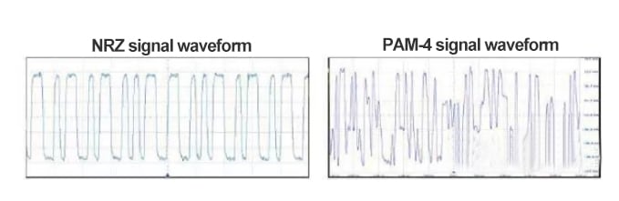
∆ NRZ Signal Frequency and PAM4 Signal Frequency Spectrum
PAM-4 vs NRZ
Since the PAM4 signal can transmit 2 bits of information per symbol period, the symbol data rate of the PAM4 signal only needs to reach half of the NRZ signal. As a result, the signal loss caused by the transmission channel is greatly reduced. It is possible that more voltage levels for information transmission such as PAM8 or even PAM16 signals will be developed as greater Ethernet speed and bandwidth are required in a connected world with instant data transmission. PAM4 has 2 bits per symbol, 4 symbol levels, and 3 eye patterns per UI; each symbol period can transmit twice as much information as NRZ.
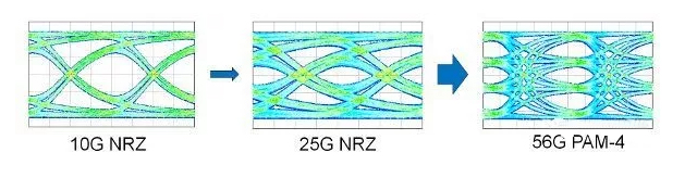
∆ Eye diagram of 10G NRZ, 25G NRZ and 56G PAM-4
PAM4 is not the latest signal modulation technique because 3 voltage levels are used for signal transmission in the most commonly used 100MBase-T Ethernet. In addition, 16QAM modulation, 32QAM modulation, and 64QAM modulation applied in the field of wireless communication all use multi-level baseband signals to modulate the carrier signal. As a popular signal coding and transmission technology for high-speed signal interconnection in the next-gen data center, PAM4 has been used in the transmission of electrical or optical signals on 100G QSFP28 and 200G even 400G interfaces.
Challenges in Analyzing PAM4 Signal
PAM4 is a 4-level pulse amplitude signal modulation technique, which can display more bit logic information than traditional digital signals. However, it is challenging to design and test PAM4 signals. For example, the PAM4 signal has a worse Signal-to-Noise Ratio (SNR), which may reach 9.5dB in the same condition of system noise.
Besides, there are 16 switching states in the PAM4 signal, which will cause the vertical asymmetry of the upper and lower eye diagrams. Furthermore, the eye width measured at the intersection point and the middle of the eye height tends to be different. Non-linear problems are also more likely to occur.
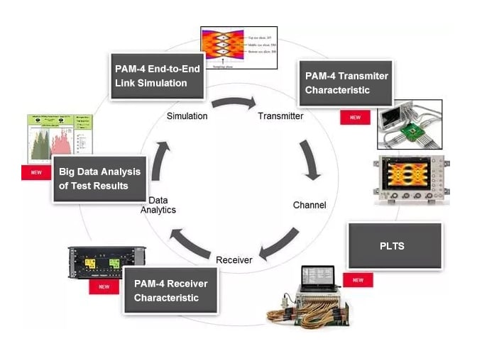
∆ Flow Diagram of Ethernet PAM4 Signal Generation and Testing
Although the symbol rate of the PAM4 signal is reduced, the channel loss of 10dB or more will still lead to a complete close in the signal eye diagram of the receiver. Therefore, pre-emphasis at the transmitting end and signal equalization at the receiving end are two important factors in terms of PAM4 signal design and testing.
PAM4 Transmitter Test Challenges
When it comes to transmitters based on PAM4, there are a few key testing parameters including extinction ratio, optical modulation amplitude, TWDP(transmitter wavelength dispersion price), transmitter linearity, and jitter.
The electrical parameters of the PAM4 transmitter can be measured by a real-time oscilloscope or a sampling oscilloscope. For the 26.56G Baud signal defined by IEEE, it is recommended to use an oscilloscope with a bandwidth of at least 33GHz for electrical parameter testing. Such an oscilloscope is designed with a frequency response curve of a fourth-order Bessel-Thomson filter.
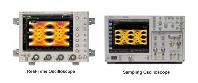
∆ Oscilloscopes for Pulse Amplitude Modulation (PAM-4) Transmitter Analysis
A sampling oscilloscope only requires an oscilloscope module with a bandwidth of 33GHz or more since its frequency response curve is similar to the shape of the fourth-order Bessel-Thomson filter. But a real-time oscilloscope usually applies a brick wall-type frequency response. Therefore, it is suggested that an oscilloscope module adopt a bandwidth of at least 50GHz in order to simulate the required frequency response curve.
PAM4 Receiver Interference Tolerance
For PAM4 receiver devices, interference tolerance(tolerance to harsh signals) is one of the crucial transmitter specifications. The purpose of the PAM4 receiver testing is to introduce an accurate but manageable defective signal into the receiving end. Thus, the interference tolerance can be measured according to the variation of bit error ratio (BER).
OIF CEI 4.0 Test Pattern for PAM4
The following graphics define the interference tolerance testing method of the 56G-VSR-PAM-4 module in the OIF CEI 4.0 Draft specification. In this methodology, the measuring devices are required to have sufficient flexibility and parameter adjustment capability.
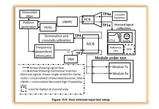
∆ Test Pattern for 56G-VSR-PAM-4 Module Tx and Rx
In this case, this specification test setup poses challenges in many aspects. For example, you have to think about how to generate a self-adaptive or PRBS31Q PAM4 encoded signals; how to simulate the pre-emphasis on the transmitter. Because deterministic jitter is predictable when compared to random jitter, you also have to figure out how to design your transmitter and receiver to eliminate it. Moreover, issues like how to simulate channel insertion loss, how to simulate communications tampering caused by adjacent channels, and how to calibrate and correct the signal at the compliance test are all huge challenges in this testing methodology.
Bit Error Ratio (BER) Tester for PAM4 Signal
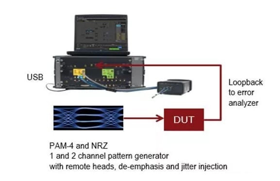
A high-performance bit error ratio tester that is able to support the flexible parameter adjustment for pulse amplitude modulation is an effective approach to deal with the challenges above. If a DUT(Device Under Test) features a forward error correction function internally, the bit error ratio(BER) can be measured in this internal tester. If not, the received data can be looped back and transmitted to the error detection module of the bit-error tester. Thus, the bit error ratio can be determined finally.
In addition to the linearity interference tolerance, the receiving capabilities are another key PAM4 transmitter parameter. But it is also challenging to define when the jitter, signal noise, and ISI (inter-symbol interference) exist. Fortunately, a signal generator in an error detector(or BER tester) to generate signals with jitter, noise, and inter-symbol interference can make a difference. Such signals are injected into the transmitter and the Bit Error Ratio (BER) can be tested by the internal error count or the means of data looping. This kind of signal used to inject into the receiving end for the margin test is usually called a stress signal.
∆ High-speed PAM4 Signal BER Measurement Solution
Compared with Rule 121 and Rule 122 in IEEE 802.3bs, this methodology provides a repetitive error correction for the optical limit eye diagram, saving hours of calibration time. While the N4917BSCA software can control and set up all necessary instruments for calibration, receiver sensitivity, and jitter tolerance testing.
PAM4 PLTS Signal Integrity Testing
PLTS(physical layer test system) is becoming a bottleneck in high-speed serial link systems. In the time of low data rate networking, the interconnect voltage level length is relatively short. Signal integrity is mainly related to drivers and receivers.
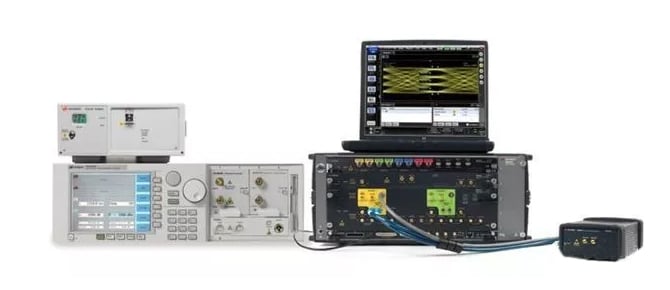
∆ N4917BSCA for Optical Receiver Stress Signal Test
When clock recovery speed, bus speed, and link speed all exceed gigabit per second, physical layer characteristic plays a more and more important role in a PAM4 signal link simulation. Another challenge to data design engineers currently is the trend of digital design to differential topology, since they must analyze all possible operating modes in order to have a comprehensive understanding of device performance. As the combined analysis of time domain and frequency domain analysis becomes more and more important, the management of multiple test systems becomes more and more difficult.
Conclusion
PAM4 technology can effectively improve the efficiency of bandwidth utilization. Also, PAM4 adopts a high-order modulation format, which reduces the number of optical devices used, the performance, cost, and power in different applications. With the advent of big data and cloud computing as well as the growing traffic, a more complex modulation technique is urgently needed. Therefore, PAM4 is becoming a crucial signal modulation technique in the hyperscale data center service, widely used in the transmission of electrical or optical signals on 200G/400G interfaces.
FiberMall provides 100G QSFP28 PAM4 single lambda fiber optics transceiver series designed for use in 100 Gigabit Ethernet. As the market moves to PAM4-based modulation, FiberMall continues to get over the technical difficulty and move forward to 200G, and 400G PAM4 interconnection solutions in the optical communication world.
Related Products:
-
 QSFP-DD-400G-FR4 400G QSFP-DD FR4 PAM4 CWDM4 2km LC SMF FEC Optical Transceiver Module
$500.00
QSFP-DD-400G-FR4 400G QSFP-DD FR4 PAM4 CWDM4 2km LC SMF FEC Optical Transceiver Module
$500.00
-
QSFP-DD-400G-SR8 400G QSFP-DD SR8 PAM4 850nm 100m MTP/MPO OM3 FEC Optical Transceiver Module
$149.00
-
QSFP-DD-400G-DR4 400G QSFP-DD DR4 PAM4 1310nm 500m MTP/MPO SMF FEC Optical Transceiver Module
$400.00
-
QSFP56-200G-FR4S 200G QSFP56 FR4 PAM4 CWDM4 2km LC SMF FEC Optical Transceiver Module
$650.00
-
QSFP-DD-200G-LR4 200G QSFP-DD LR4 PAM4 LWDM4 10km LC SMF FEC Optical Transceiver Module
$1000.00
-
QSFP28-100G-DR1 100G QSFP28 Single Lambda DR 1310nm 500m LC SMF with FEC DDM Optical Transceiver
$180.00
-
QSFP28-100G-FR1 100G QSFP28 Single Lambda FR 1310nm 2km LC SMF with FEC DDM Optical Transceiver
$215.00
-
QSFP28-100G-LR1 100G QSFP28 Single Lambda LR 1310nm 10km LC SMF with FEC DDM Optical Transceiver
$265.00