

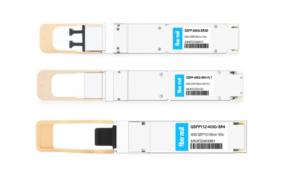
- FiberMall
Harper Ross
Answered on 1:59 am
Yes, the 400G-FR4 and 400G-LR4 transceivers can interoperate up to a reach of 2km (limited by the FR4). Note that max allowed Receiver power for the 400G-FR4 (max Rx power of 3.5dBm) may require a minimum level of attenuation to be present if connected to a 400G-LR4 transmitter (Max Tx power of 5.1dBm).
According to the Cisco 400G QSFP-DD Cable and Transceiver Modules Data Sheet, the 400G-FR4 and the 400G-LR4 transceivers are both compliant to the 100G Lambda MSA standard, which defines a common optical interface for 100G per wavelength applications. The 400G-FR4 and the 400G-LR4 transceivers use four optical lanes, each carrying a 100G PAM4 signal, over a duplex LC single-mode fiber. The main difference between them is the transmission distance: the 400G-FR4 can reach up to 2km, while the 400G-LR4 can reach up to 10km.
Therefore, to interoperate these transceivers, they need to have compatible wavelengths, power budgets, and dispersion compensation. The 100G Lambda MSA specifies two sets of wavelengths for 100G per wavelength applications: LAN-WDM (1295.56nm, 1300.05nm, 1304.58nm, and 1309.14nm) and CWDM4 (1271nm, 1291nm, 1311nm, and 1331nm).
People Also Ask
CCWDM vs CWDM: When Compact CWDM Actually Pays Off
A CCWDM (Compact CWDM) module performs the same wavelength multiplexing and demultiplexing functions as a conventional CWDM module, but uses a more compact optical architecture. By integrating thin-film filters into a free-space micro-optical assembly, it reduces internal fiber interconnections and can lower insertion loss while significantly reducing package size. Both
NVIDIA RoCEv2 Configuration Guide: Mastering Spectrum-4, ConnectX, and Spectrum-X End-to-End Lossless Networking
Building a high-performance AI cluster requires more than powerful GPUs and high-speed Ethernet switches. Network congestion, packet loss, and inconsistent RDMA configurations can significantly reduce distributed training efficiency. NVIDIA RoCEv2 enables Remote Direct Memory Access (RDMA) over routable Ethernet networks, reducing CPU involvement and supporting high-throughput GPU communication. Combined with NVIDIA
DAC Cable vs Optical Module: Reach, Power, and Cost per Link
A DAC cable is usually the better choice for short, fixed data center links under about 3 m, where cost, power consumption, and latency are important considerations. An optical module paired with fiber is generally the better choice when a link needs to reach farther, connect through patch panels, support
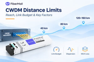
CWDM Distance Limits: How Far CWDM Can Reach
How far can CWDM transmit? The answer depends on the data rate, operating wavelength, optical power budget, fiber characteristics, and passive component losses. Typical CWDM transceiver specifications cover a wide range of distances. At 10G, shorter-wavelength modules are commonly rated for 10 to 40 km, while selected longer-wavelength modules support
Passive vs Active DAC Cable: Reach, Power & When to Use
Passive and active DAC cables both transmit electrical signals over shielded twinax copper. The key difference is how they handle signal degradation. Passive DAC cables rely on the host SerDes for signal transmission and equalization, while active copper cables add signal-conditioning electronics inside the connectors. These electronics may use analog
Related Articles

800G SR8 and 400G SR4 Optical Transceiver Modules Compatibility and Interconnection Test Report
Version Change Log Writer V0 Sample Test Cassie Test Purpose Test Objects:800G OSFP SR8/400G OSFP SR4/400G Q112 SR4. By conducting corresponding tests, the test parameters meet the relevant industry standards, and the test modules can be normally used for Nvidia (Mellanox) MQM9790 switch, Nvidia (Mellanox) ConnectX-7 network card and Nvidia (Mellanox) BlueField-3, laying a foundation for
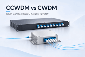
CCWDM vs CWDM: When Compact CWDM Actually Pays Off
A CCWDM (Compact CWDM) module performs the same wavelength multiplexing and demultiplexing functions as a conventional CWDM module, but uses a more compact optical architecture. By integrating thin-film filters into a free-space micro-optical assembly, it reduces internal fiber interconnections and can lower insertion loss while significantly reducing package size. Both
NVIDIA RoCEv2 Configuration Guide: Mastering Spectrum-4, ConnectX, and Spectrum-X End-to-End Lossless Networking
Building a high-performance AI cluster requires more than powerful GPUs and high-speed Ethernet switches. Network congestion, packet loss, and inconsistent RDMA configurations can significantly reduce distributed training efficiency. NVIDIA RoCEv2 enables Remote Direct Memory Access (RDMA) over routable Ethernet networks, reducing CPU involvement and supporting high-throughput GPU communication. Combined with NVIDIA
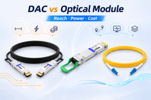
DAC Cable vs Optical Module: Reach, Power, and Cost per Link
A DAC cable is usually the better choice for short, fixed data center links under about 3 m, where cost, power consumption, and latency are important considerations. An optical module paired with fiber is generally the better choice when a link needs to reach farther, connect through patch panels, support
CWDM Distance Limits: How Far CWDM Can Reach
How far can CWDM transmit? The answer depends on the data rate, operating wavelength, optical power budget, fiber characteristics, and passive component losses. Typical CWDM transceiver specifications cover a wide range of distances. At 10G, shorter-wavelength modules are commonly rated for 10 to 40 km, while selected longer-wavelength modules support

Passive vs Active DAC Cable: Reach, Power & When to Use
Passive and active DAC cables both transmit electrical signals over shielded twinax copper. The key difference is how they handle signal degradation. Passive DAC cables rely on the host SerDes for signal transmission and equalization, while active copper cables add signal-conditioning electronics inside the connectors. These electronics may use analog
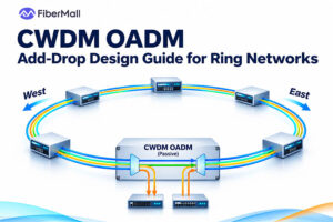
CWDM OADM: Add-Drop Design Guide for Ring Networks
A CWDM OADM adds and drops selected wavelengths at an intermediate site while all other channels continue along the express path without being dropped or converted. Use one when one or more channels need to leave or join a fiber mid-span. Use a mux/demux at terminal sites, where all channels
Related Posts
- Understanding MTP® Trunk Cables: The Backbone of High-Density Fiber Networks
- Market Forecast for AEC, DAC, and AOC
- Multilayer Switch Technology Principle: Layer 2, Layer 3, Layer 4 Switch
- Understanding Network Interface: Key Concepts and Importance Explained
- Unlocking the Potential of Nvidia MPO Cables for Next-Gen Fiber Networks
