
Building a high-performance AI cluster requires more than powerful GPUs and high-speed Ethernet switches. Network congestion, packet loss, and inconsistent RDMA configurations can significantly reduce distributed training efficiency.
NVIDIA RoCEv2 enables Remote Direct Memory Access (RDMA) over routable Ethernet networks, reducing CPU involvement and supporting high-throughput GPU communication.
Combined with NVIDIA Spectrum-X Ethernet, Spectrum-4 switches, and ConnectX adapters, RoCEv2 provides a powerful foundation for AI networking.
This guide covers hardware selection, rail-optimized architecture, PFC/ECN configuration, congestion control, performance validation, and troubleshooting.
Why Lossless Matters: A Real Failure Case
The 30% Throughput Drop That Ping Couldn’t Detect
Consider an illustrative 256-GPU training cluster where NCCL all-reduce throughput drops by 30% during peak workloads.
Basic connectivity tests show normal latency and no obvious packet loss. Yet simultaneous GPU communication creates congestion at switch egress ports.
Typical symptoms include:
- Normal ICMP ping results but poor NCCL throughput.
- Increased RDMA retransmissions during incast traffic.
- Rising PFC pause counters or buffer occupancy.
- Performance degradation only under concurrent workloads.
The 30% figure is an illustrative troubleshooting scenario, not a measured NVIDIA benchmark.
Key lesson: Ping verifies IP connectivity, not the congestion behavior of an RDMA fabric.
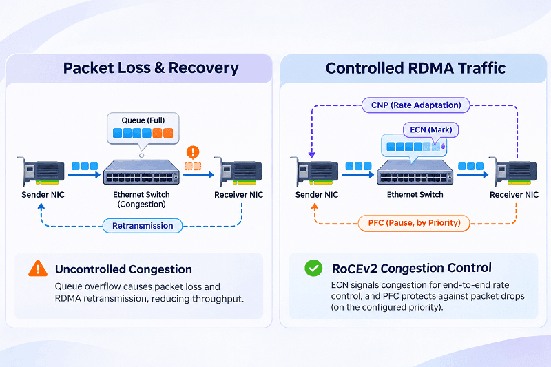
One Lost Packet Costs an Order of Magnitude, Not Just a Little Latency
RoCEv2 reliable transport uses acknowledgments and retransmission mechanisms to recover from packet loss.
Depending on the NIC generation, transport behavior, and recovery implementation, a missing packet may trigger additional retransmission work, delay outstanding operations, and reduce effective throughput.
Under heavy congestion, the resulting performance penalty can greatly exceed the transmission time of the lost packet.
However, a tenfold penalty is not universal.
Proper congestion management aims to prevent packet loss while avoiding excessive PFC pauses and head-of-line blocking.
NVIDIA AI Ethernet Product Stack: Switches, NICs, and DPUs
The Three-Layer Portfolio: Spectrum, ConnectX, BlueField
NVIDIA’s Ethernet networking portfolio combines three major components:
| Component | Primary Function |
| Spectrum Ethernet switches | High-bandwidth switching, routing, buffering, and congestion management |
| ConnectX NICs and SuperNICs | RDMA connectivity, hardware acceleration, and GPU communication |
| BlueField DPUs and SuperNICs | Infrastructure offload, security, storage networking, and accelerated connectivity |
Spectrum-X integrates compatible switching, endpoint hardware, software, and congestion-control capabilities into an optimized Ethernet platform.
A Spectrum-4 switch alone does not automatically provide the complete Spectrum-X feature set.
Switch Lineup: Spectrum-4 SN5600, SN5400, and Legacy Spectrum-3
Two important Spectrum-4 platforms are:
| Switch | Maximum Ethernet Configuration | Switching Capacity |
| SN5400 | 64 × 400GbE QSFP-DD | 25.6 Tbps |
| SN5600 | 64 × 800GbE OSFP | 51.2 Tbps |
| Spectrum-3 systems | Model-dependent, typically up to 400GbE | Model-dependent |
The SN5600 supports high-density 800G connections and flexible 400G breakout configurations.
The SN5400 is suitable for 400G-based architectures requiring substantial port density.
Spectrum-3 remains relevant for compatible existing deployments, although Spectrum-X capabilities and platform support must be verified separately.
Host-Side Adapters: ConnectX-7, ConnectX-8, and BlueField-3
ConnectX-7 supports Ethernet connectivity up to 400Gb/s, making it suitable for high-performance GPU servers.
ConnectX-8 SuperNIC supports up to 800Gb/s aggregate connectivity, including configurations using two 400G ports.
BlueField-3 provides DPU-based infrastructure acceleration and, in SuperNIC variants, high-speed networking for AI workloads.
Selection should consider:
- Required network bandwidth per GPU.
- PCIe generation and available host bandwidth.
- GPUDirect RDMA compatibility.
- Ethernet port configuration.
- Firmware and Spectrum-X software support.
Not every adapter variant supports the same capabilities.
Inside the Server: GPU, NVLink, PCIe, and HBM Bandwidth Math
GPU memory bandwidth and network bandwidth represent different performance limits.
For example:
- 400GbE provides 50GB/s of nominal line-rate bandwidth.
- 800GbE provides 100GB/s of nominal line-rate bandwidth.
- Eight 400GbE connections provide 3.2Tb/s, or 400GB/s, of aggregate nominal bandwidth.
Actual application throughput is lower because of protocol overhead and implementation limits.
HBM handles local GPU memory access, while NVLink accelerates supported GPU-to-GPU communication. PCIe and network adapters provide additional communication paths.
A fast NIC cannot compensate for insufficient PCIe bandwidth or inefficient GPU communication patterns.
Product Selection Cheat Sheet
| Requirement | Potential Choice |
| 400G AI Ethernet fabric | SN5400 + ConnectX-7 |
| High-density 800G switching | SN5600 |
| Up to 800G host connectivity | ConnectX-8 SuperNIC |
| Infrastructure and storage offload | BlueField-3 DPU |
| Integrated NVIDIA AI Ethernet fabric | Validated Spectrum-X architecture |
These are component-level examples, not complete validated system configurations.
Three Procurement Pitfalls: Optics, FEC, and Breakout Ports
Three mistakes frequently complicate deployment.
1. Optical compatibility: Verify form factors, electrical interfaces, optical specifications, connector types, and supported reach.
2. FEC mismatches: Ensure both ends support compatible Forward Error Correction configurations for the selected Ethernet mode.
3. Incorrect breakout assumptions: An 800G physical port may support multiple logical connections, but supported modes depend on the switch, transceiver, firmware, and cable assembly.
Always validate the complete switch-to-NIC connection before purchasing optics or DAC/AOC cables.
Reference Architecture: Rail-Optimized Topology with Separate Compute and Storage Fabrics
Two Spine-Leaf Layers Are Enough Below a Thousand GPUs
A two-tier leaf-spine fabric can support many GPU clusters below 1,000 GPUs without introducing a third switching tier.
However, GPU count alone cannot determine the required topology.
Important factors include switch radix, port speeds, oversubscription ratio, redundancy requirements, rail count, and east-west traffic patterns.
For relatively small clusters, a collapsed architecture may be more economical.
For larger deployments, dedicated compute fabrics provide more predictable performance.
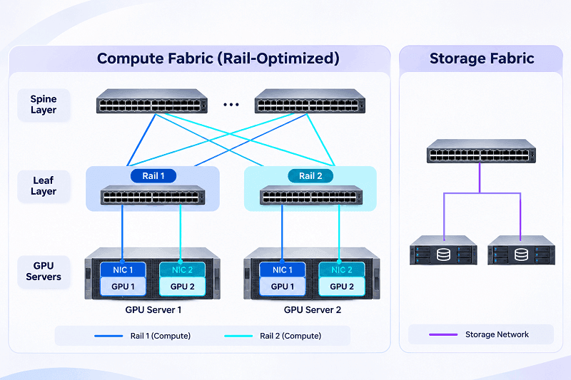
Principle 1: Physically Separate Compute and Storage Networks
AI compute traffic and storage traffic have different characteristics.
Compute fabrics often carry latency-sensitive collective operations such as NCCL all-reduce.
Storage fabrics handle dataset transfers, checkpoint operations, and distributed storage access.
Separating these networks can:
- Reduce congestion interference.
- Simplify QoS policies.
- Improve troubleshooting.
- Provide independent scaling paths.
Physical separation is a recommended design option for demanding clusters, not a universal RoCEv2 requirement.
Principle 2: Rail-Optimized Access Design
Rail-optimized networking groups corresponding GPU network interfaces across servers into consistent network rails.
For example, the first compute NIC on each server connects to Rail 1, while the second connects to Rail 2.
This arrangement helps align communication paths with GPU topology and enables predictable traffic distribution.
Rail mapping must match the server’s actual GPU-to-NIC affinity rather than assuming every system has identical PCIe and NVLink layouts.
A Worked Example: 256-GPU POD Sizing
Consider a cluster with:
- 32 servers.
- 8 GPUs per server.
- 8 dedicated 400GbE network connections per server.
- 256 total compute-facing network connections.
Aggregate nominal endpoint bandwidth:
256 × 400Gb/s = 102.4Tb/s
An illustrative non-oversubscribed fabric using 64-port 400GbE logical switch configurations could use:
| Network Layer | Illustrative Allocation |
| Compute endpoints | 256 × 400G |
| Leaf switches | 8, each with 32 downlinks and 32 uplinks |
| Spine switches | 4, each with 64 leaf-facing connections |
| Oversubscription | 1:1 |
This is a simplified logical sizing example, not an NVIDIA-validated bill of materials. Physical port breakout, rail separation, failure domains, and cabling must be engineered separately.
Two Decisions to Lock at Design Time: Cable Length and Buffer Roles
First, determine link lengths and cable technologies before calculating PFC headroom.
Second, define which traffic classes use lossless buffers and which remain best-effort.
Cable delay, link speed, and congestion-response time influence required buffer capacity.
Incorrect assumptions can cause premature PFC activation or packet drops under burst traffic.
What Makes Spectrum-X Different: Adaptive Routing and End-to-End Congestion Control
ECMP Hash Polarization and the Adaptive Routing Fix
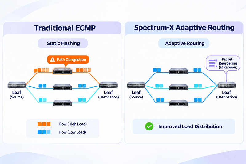
Traditional Equal-Cost Multi-Path routing generally selects paths using packet-header hashing.
Multiple large flows can collide on the same path, leaving other links underutilized.
Spectrum-X introduces RoCE-aware adaptive routing to distribute traffic across available paths according to network conditions.
Unlike conventional static ECMP, supported Spectrum-X implementations can distribute packets across multiple paths and use endpoint capabilities to handle out-of-order delivery.
This improves bandwidth utilization under suitable traffic conditions.
Flowlet Switching: The Compromise That Depends on Measured Latency
Flowlet switching distributes bursts of a flow across different paths when sufficiently large idle gaps occur.
It can reduce packet reordering compared with unrestricted packet spraying, but its effectiveness depends on traffic patterns and path-delay differences.
Spectrum-X RoCE Adaptive Routing should not be confused with ordinary flowlet switching.
NVIDIA’s integrated approach can use packet-level distribution with compatible endpoint reordering capabilities.
Deployment should follow the supported Spectrum-X configuration profile.
Dynamic Congestion Control and GPUDirect RDMA
Dynamic congestion control adjusts traffic injection rates in response to congestion signals and network conditions.
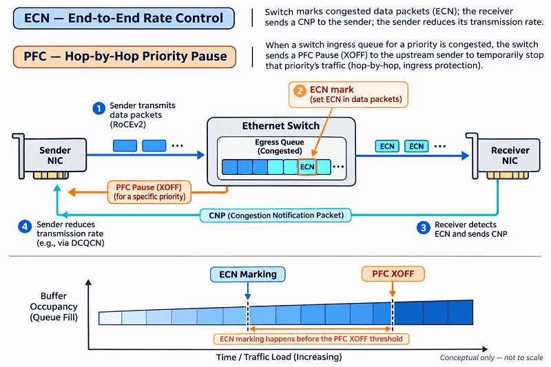
RoCEv2 commonly uses Explicit Congestion Notification (ECN), Congestion Notification Packets (CNPs), and endpoint rate adaptation.
PFC provides an additional hop-by-hop protection mechanism when configured.
Meanwhile, GPUDirect RDMA enables supported NICs and GPUs to transfer data without unnecessary intermediate CPU-memory copies.
Together, these technologies help reduce communication overhead and improve distributed AI performance.
RoCEv2 vs. InfiniBand: The Cost-Performance Trade-Off
| Factor | RoCEv2 Ethernet | InfiniBand |
| Network protocol | Routable Ethernet/IP | Native InfiniBand |
| RDMA support | Yes | Yes |
| Congestion management | Requires coordinated Ethernet/RDMA tuning | Integrated IB mechanisms |
| Ecosystem | Broad Ethernet infrastructure | Specialized HPC/AI ecosystem |
| Deployment trade-off | Ethernet integration and flexibility | Purpose-built RDMA fabric |
Neither is universally superior.
Actual cost and performance depend on cluster scale, workload, operational expertise, and selected hardware.
The Lock-In Trade-Offs You Accept
RoCEv2 is based on open networking standards, but advanced Spectrum-X functionality depends on compatible NVIDIA hardware and software.
Organizations should distinguish basic interoperable RoCEv2 operation from NVIDIA-specific adaptive routing, telemetry, and integrated optimizations.
This distinction matters when planning multivendor expansion.
Step-by-Step Configuration: Spine, Leaf, and Server
Why PFC Beats Dropping: The Go-Back-N Economics
Packet drops can trigger expensive recovery in RDMA reliable connections.
Some retransmission behaviors resemble Go-Back-N recovery, where more data than the original lost packet may need retransmission.
PFC can temporarily pause selected traffic priorities before buffer exhaustion causes packet loss.
However, excessive PFC introduces head-of-line blocking and can propagate congestion.
The preferred strategy is ECN-based congestion avoidance with carefully controlled PFC as a safety mechanism, rather than continuous pausing.
Spine Configuration (Spectrum-4 with NVUE)
On supported NVIDIA Spectrum switches running Cumulus Linux, NVUE provides a predefined RoCE QoS configuration.
A baseline lossless configuration is:
nv set qos roce mode lossless
nv set qos roce cable-length 100
nv config apply
The cable-length value is in meters and must reflect the deployment’s requirements.
Verify the applied configuration:
nv show qos roce
The profile configures key RoCE QoS elements, including PFC, ECN, traffic classification, and buffering.
IP addressing, routing, ECMP, interface breakout, MTU, and Spectrum-X-specific features require additional platform-specific configuration.
Leaf Configuration (SN5600 / SN5400)
Leaf switches require the same coordinated RoCE QoS strategy.
nv set qos roce mode lossless
nv config apply
nv show qos roce
Confirm that host-facing and spine-facing interfaces have consistent traffic classification and congestion-control behavior.
For an individual port:
nv show interface swp1 qos roce status
nv show interface swp1 qos roce counters
Replace swp1 with the actual interface.
These examples assume compatible Cumulus Linux releases. NVIDIA Onyx and other operating systems use different command syntax.
The Threshold Algorithm: PFC Headroom and ECN Watermarks
ECN should normally signal congestion before queues reach the conditions requiring PFC protection.
PFC headroom must accommodate traffic that can arrive after a pause is triggered.
A conceptual estimate is:
Headroom ≥ Link Rate × Effective Pause-Response Time + Safety Margin
Convert the link rate to bytes per second before calculating memory requirements.
The complete calculation also depends on ASIC behavior, pipeline delay, maximum packet size, and buffer architecture.
Do not copy ECN thresholds or PFC XOFF/XON values between different switch platforms without validation.
Start with NVIDIA’s supported profile and adjust only when measurements justify changes.
Server Configuration: ConnectX in Eight Steps
Configure each ConnectX host adapter using the following workflow.
- Verify hardware and firmware: Confirm adapter model, supported Ethernet mode, driver version, and firmware compatibility.
- Identify RDMA interfaces: Use rdma link show, ibv_devinfo, and ethtool.
- Configure IP connectivity: Assign addresses and verify routes across the compute fabric.
- Set a consistent MTU: Use an Ethernet MTU such as 9000 where supported end-to-end.
- Configure traffic classification: Align NIC DSCP/PCP mappings with switch QoS policies.
- Enable required PFC priorities: Confirm local or DCBX-managed settings match the network.
- Verify ECN congestion control: Check NIC reaction/notification behavior and supported firmware settings.
- Validate RDMA and GPU workloads: Run RDMA performance tests followed by NCCL benchmarks.
For a locally managed ConnectX interface, an illustrative priority-3 configuration is:
mlnx_qos -i <iface> –trust dscp
mlnx_qos -i <iface> –dscp2prio set,26,3
mlnx_qos -i <iface> –pfc 0,0,0,1,0,0,0,0
Here, DSCP 26 is an example policy value, not a universal RoCEv2 standard. The priority mapping must match the actual fabric configuration.
Avoid conflicting local and firmware-managed DCBX settings.
The Six Iron Rules of RoCEv2 Lossless Configuration
- Keep traffic classification consistent across every participating network hop.
- Configure compatible PFC behavior on both ends of each required link.
- Use ECN to manage congestion before PFC becomes excessive.
- Size buffers and headroom for link speeds and actual cable lengths.
- Validate MTU, FEC, link mode, and optical compatibility end-to-end.
- Verify configuration persistence and workload performance after changes.
A single misconfigured port can undermine an otherwise carefully designed fabric.
The Persistence Trap That Costs Days of Debugging
A network may perform correctly before rebooting and fail afterward because NIC settings or switch configurations were not preserved.
Cumulus Linux behavior is version-dependent:
- In Cumulus Linux 5.8 and earlier, nv config apply does not save configuration by default.
- In Cumulus Linux 5.9 and later, automatic saving is enabled by default.
Use nv config save where required and verify the actual startup configuration.
Host-side commands executed through tools such as mlnx_qos may also require persistent configuration management.
Reboot testing should be part of acceptance testing.
Validation and Troubleshooting Checklist
Pre-Launch Checklist
Before production deployment, confirm:
- All Ethernet links negotiate expected speeds and FEC.
- RoCEv2 traffic uses the intended priorities.
- PFC and ECN operate correctly across all required paths.
- MTU values are compatible end-to-end.
- No unexplained packet drops or physical-layer errors occur.
- Adaptive routing is enabled only on supported configurations.
- RDMA and NCCL tests meet established baseline targets.
- Settings survive server and switch reboots.
Essential Read-Back Commands
Useful switch commands include:
nv show qos roce
nv show interface qos-roce-status
nv show interface qos-roce-counters
Useful host-side diagnostics include:
rdma link show
ibv_devinfo
ethtool -S <iface>
mlnx_qos -i <iface>
Command availability depends on the installed driver and software packages.
Record baseline counters before applying workload traffic, then compare changes afterward.
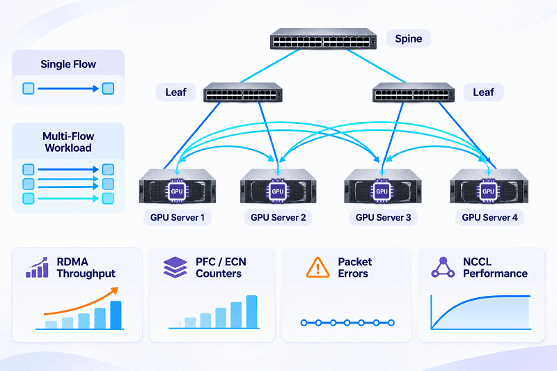
Why a Single Full-Rate Flow Proves Nothing
A single RDMA flow may achieve excellent bandwidth while the fabric performs poorly during distributed workloads.
AI training creates simultaneous communication patterns, including all-to-all exchanges and synchronized collectives.
Validation should include:
- Multiple concurrent RDMA flows.
- Incast and mixed-size transfers.
- NCCL all-reduce and all-to-all.
- Long-duration congestion testing.
- Link-failure and recovery scenarios.
Measure aggregate throughput, tail latency, PFC activity, ECN/CNP behavior, retransmissions, and GPU utilization.
Common Failures, Root Causes, and First Diagnostic Steps
| Symptom | Possible Cause | First Diagnostic Step |
| Low NCCL bandwidth | Congestion or routing imbalance | Inspect ECN/PFC counters and path utilization |
| RDMA connection failure | Addressing, routing, or GID mismatch | Verify RDMA interfaces and IP routes |
| Excessive PFC pauses | Congestion or insufficient buffering | Inspect affected priorities and queue occupancy |
| Intermittent packet loss | FEC, optics, or physical-link errors | Check port error counters and module diagnostics |
| Performance drop after reboot | Nonpersistent settings | Compare active and saved configurations |
| Uneven spine utilization | ECMP polarization or routing configuration | Inspect load distribution and routing state |
Field Lessons from Ten-Thousand-GPU Operations
Large AI clusters magnify small configuration inconsistencies.
Operational practices that become especially important at scale include:
- Automated firmware and configuration management.
- Per-port telemetry and long-term counter collection.
- Continuous NCCL performance baselines.
- Change tracking for QoS and routing policies.
- Early detection of degraded optical links.
- Staged rollout and rollback procedures.
These are general large-scale operations recommendations, not claims of a specific FiberMall production deployment.
FAQ: NVIDIA RoCEv2 and Spectrum-X Configuration
Does PFC Need to Be Enabled on Both the Switch and the NIC?
For links using PFC-based lossless operation, both endpoints must support and correctly configure the required priority.
Because pause frames operate hop-by-hop, all relevant links along the path need coordinated policies.
Which Priority Should RoCEv2 Traffic Use by Default?
NVIDIA Cumulus Linux’s conventional lossless RoCE profile uses switch priority 3 for RoCE traffic and priority 6 for congestion notification traffic.
However, priority selection is configurable and must match the deployed QoS policy.
Why Does NCCL all_reduce Slow Down Even When Ping and Single-Stream Tests Pass?
NCCL all-reduce produces concurrent traffic that can expose congestion, ECMP imbalance, PFC propagation, or insufficient buffering.
Ping and single-stream tests do not reproduce these distributed communication patterns.
What MTU Should I Use for RoCEv2?
An Ethernet MTU around 9000 bytes is common in AI data centers when every device in the path supports it.
However, Ethernet MTU and RDMA path MTU are different parameters. Supported RDMA path MTU values depend on the adapter and configuration.
RoCEv2 or InfiniBand: Which Should I Choose for My GPU Cluster?
Choose based on application benchmarks, existing network infrastructure, cost, scalability, and operational expertise.
RoCEv2 provides Ethernet integration, while InfiniBand offers a purpose-built RDMA networking ecosystem.
Why Did RoCEv2 Performance Drop After a Server Reboot?
Potential causes include lost QoS settings, changed interface names, driver initialization differences, firmware configuration changes, or altered RDMA interface mappings.
Compare pre-reboot and post-reboot configurations before changing congestion thresholds.
Conclusion: Configuration Discipline Beats Hardware Specs
A successful NVIDIA RoCEv2 deployment depends on coordinated hardware, topology, congestion management, and continuous validation.
Spectrum-X Ethernet, Spectrum-4 switches, and ConnectX adapters provide advanced capabilities, but correct PFC/ECN configuration, consistent QoS policies, and reliable physical connectivity remain essential.
For AI cluster deployments, FiberMall provides high-speed optical transceivers, DAC cables, AOC cables, and fiber connectivity solutions for compatible 100G, 200G, 400G, and 800G Ethernet environments.
Selecting the right interconnect components and validating the complete network path are critical steps toward reliable, high-performance AI infrastructure.
Related Products:
-
 NVIDIA Q3200-RA Quantum-3 XDR InfiniBand Switch, 2U, 36x 800Gb/s XDR Ports, 18 OSFP Cages, 4 PSUs (No Power Cords), Managed, C2P Airflow, Standard Depth, Rail Kit
$67500.00
-
NVIDIA MQM8790-HS2F Quantum HDR InfiniBand Switch, 40 x HDR QSFP56 Ports, Two Power Supplies (AC), Unmanaged, x86 Dual Core, Standard Depth, P2C Airflow, Rail Kit
$18500.00
-
NVIDIA MQM8700-HS2F Quantum HDR InfiniBand Switch, 40 x HDR QSFP56 Ports, Two Power Supplies (AC), Managed, x86 Dual Core, Standard Depth, P2C Airflow, Rail Kit
$17000.00
-
NVIDIA MQM9790-NS2R Quantum-2 NDR InfiniBand Switch, 64-ports NDR 400Gb/s, 32 OSFP Ports, Unmanaged, P2C Airflow (reverse)
$30000.00
-
NVIDIA MQM9790-NS2F Quantum-2 NDR InfiniBand Switch, 64 x 400Gb/s Ports, 32 OSFP Cages, Unmanaged, P2C Airflow(forward)
$30000.00
-
NVIDIA MQM9700-NS2R Quantum-2 NDR InfiniBand Switch, 64-ports NDR 400Gb/s, 32 OSFP Ports, Managed, P2C Airflow(reverse)
$35000.00
-
NVIDIA MQM9700-NS2F Quantum-2 NDR InfiniBand Switch, 64 x 400Gb/s Ports, 32 OSFP ports, Managed, P2C Airflow(forward)
$35000.00
-
NVIDIA Q3400-RA Quantum-3 XDR InfiniBand Switch, 4U, 144x 800Gb/s XDR Ports, 72 OSFP Cages, 8 PSUs (No Power Cords), Managed, C2P Airflow, Standard Depth, Rail Kit
$135000.00
-
NVIDIA MMA4Z00-NS Compatible 800GBASE 2 x SR4/SR8 OSFP PAM4 850nm 100m DOM Dual MPO-12 MMF Optical Transceiver Module
$550.00
-
NVIDIA MMA4Z00-NS-FLT Compatible 800GBASE 2 x SR4/SR8 OSFP RHS/Flat Top PAM4 850nm 100m DOM Dual MPO-12 MMF Optical Transceiver Module
$600.00
-
NVIDIA MMS4X00-NM Compatible 800GBASE 2 x DR4/DR8 OSFP IHS/Closed Finned Top PAM4 1310nm 500m DOM Dual MTP/MPO-12 SMF Optical Transceiver Module
$600.00
-
NVIDIA MMS4X00-NM-FLT Compatible 800GBASE 2 x DR4/DR8 OSFP Flat Top PAM4 1310nm 500m DOM Dual MTP/MPO-12 SMF Optical Transceiver Module
$650.00
-
NVIDIA MMS4X50-NM Compatible 800G 2x FR4 OSFP IHS/Closed Finned Top PAM4 1310nm 2km DOM Dual Duplex LC SMF InfiniBand NDR Optical Transceiver Module
$1000.00
-
NVIDIA MCP7Y00-N001 Compatible 1m (3ft) 800Gb Twin-port OSFP to 2x400G OSFP InfiniBand NDR Breakout Direct Attach Copper Cable
$160.00
-
NVIDIA MCA7J60-N004 Compatible 4m (13ft) 800G Twin-port OSFP to 2x400G OSFP InfiniBand NDR Breakout Active Copper Cable
$800.00
-
NVIDIA MMA4Z00-NS400 Compatible 400G OSFP SR4 Flat Top PAM4 850nm 30m on OM3/50m on OM4 MTP/MPO-12 Multimode FEC Optical Transceiver Module
$400.00
-
NVIDIA MMS4X00-NS400 Compatible 400G OSFP DR4 Flat Top PAM4 1310nm MTP/MPO-12 500m SMF FEC Optical Transceiver Module
$450.00
-
NVIDIA MMA1Z00-NS400 Compatible 400G QSFP112 VR4 PAM4 850nm 50m MTP/MPO-12 OM4 FEC Optical Transceiver Module
$385.00
-
NVIDIA MMS1X00-NS400 Compatible 400G NDR QSFP112 DR4 PAM4 1310nm 500m MPO-12 with FEC Optical Transceiver Module
$500.00
-
NVIDIA MCP7Y70-H001 Compatible 1m (3ft) 400G Twin-port 2x200G OSFP to 4x100G QSFP56 Passive Breakout Direct Attach Copper Cable
$120.00