


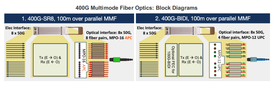
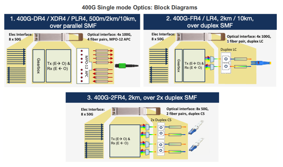
The following table and diagrams show the main features of the different 400G transceivers that Arista’s platforms support. All of these transceivers have the same electrical connector interface, which is 8 x 50Gb/s PAM-4 (for a total of 400Gb/s). However, the optical signals can vary depending on the module type. Some modules have 8 x 50Gb/s PAM-4 optical lanes, while others have 4 x 100Gb/s PAM-4 optical lanes. For the latter, a gearbox chip inside the module converts the 8 x 50Gb/s PAM-4 electrical signals (from the board) to the 4 x 100Gb/s PAM-4 signals that the optical signals need.
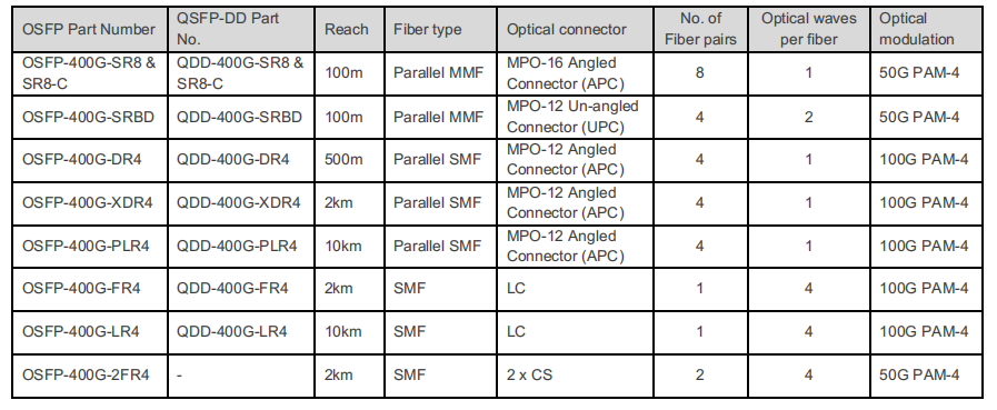
Block diagrams of each optic listed above are shown below.
800G SR8 and 400G SR4 Optical Transceiver Modules Compatibility and Interconnection Test Report
Version Change Log Writer V0 Sample Test Cassie Test Purpose Test Objects:800G OSFP SR8/400G OSFP SR4/400G Q112 SR4. By conducting corresponding tests, the test parameters meet the relevant industry standards, and the test modules can be normally used for Nvidia (Mellanox) MQM9790 switch, Nvidia (Mellanox) ConnectX-7 network card and Nvidia (Mellanox) BlueField-3, laying a foundation for

102.4T NPO Switch Design: Near-Package Optics for AI Scale-Up Networks
As AI clusters grow from hundreds to thousands of accelerators, traditional electrical and pluggable optical interconnects face increasing challenges in bandwidth density, power consumption, and signal integrity. A 102.4T NPO switch (Near-Packaged Optics switch) addresses these limitations by placing optical engines close to the switching ASIC, shortening high-speed electrical paths and
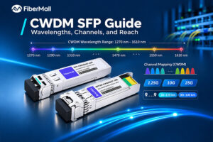
CWDM SFP Guide: Wavelengths, Channels, and Reach
The number on the CWDM SFP label is not the number on the mux port. A module arrives marked 1470 nm. The port it needs to reach is labeled CH11. Neither label mentions the other, and nothing in the box explains that they describe the same channel. That single gap
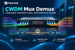
CWDM Mux Demux: Channels, Insertion Loss, and Selection Guide
The 18-channel CWDM mux demux can look like the safest purchase: room to grow, one part number, and no second trip to procurement. Then the link budget arrives. An 18-channel unit may add around 5.0 to 5.4 dB of insertion loss, while an 8-channel unit may add around 2.4 dB.

USFP Capacity Explained: From 6.4T to 12.8T AI Fabric Bandwidth
USFP is designed to scale from 6.4T to 12.8T by increasing its electrical lane count while supporting 400 Gb/s per lane. Its first planned transceivers use 16 full-duplex lanes, delivering 6.4 Tb/s of aggregate capacity. The connector architecture is designed to support future expansion to 32 lanes, potentially enabling 12.8
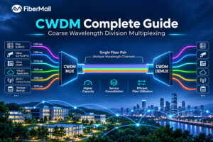
CWDM Complete Guide: Coarse Wavelength Division Multiplexing
Consider an illustrative scenario: a nine-building hospital campus has one spare fiber pair, and a new imaging center is opening in six weeks. Installing additional duct would take eight months. Daniel, the network engineer on the project, needs nine 10G services running over the fiber pair the hospital already owns.
DWDM Troubleshooting: Diagnose by Measurement, Not Guesswork
A link runs clean for two years. Then one Tuesday, two edge channels start throwing errors while the other thirty-eight remain healthy. The amplifier raises an alarm, so someone replaces it. The errors return a week later because the amplifier was never the problem. That sequence is common enough to