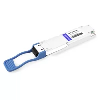
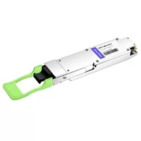
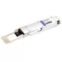
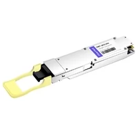
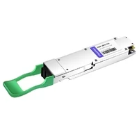
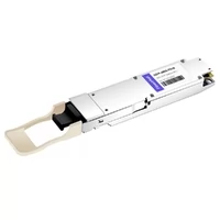
The network engineer at a mid-sized cloud provider told me about their initial 400G OSFP deployment. They placed an order for switches, modules, and cables. All items arrived on schedule. The team found out that the OSFP modules did not fit into the NVIDIA ConnectX-7 NICs, which they used to build their GPU cluster. The heatsink design was incorrect.
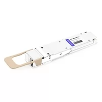
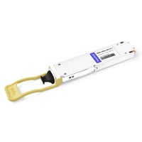
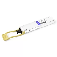
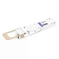
400G OSFP modules come in two physical heatsink variants: flat-top and finned-top. Finned-top heatsinks serve as the standard for most switch models. NVIDIA ConnectX-7 NICs require flat-top. This information exists as an open secret because it is a critical project element that requires hardware replacement in order to continue work.
The guide provides a complete 400G OSFP implementation process, starting from initial planning to the final production stage. The guide describes hidden dangers which datasheets fail to disclose, along with the configuration commands used in Arista, Cisco, and NVIDIA systems, and the verification procedures which ensure smooth operations during production. FiberMall supplies 400G OSFP modules and provides technical assistance for your deployment through their compatible cabling solutions.
Pre-Deployment Planning
Successful 400G deployments start long before you rack the first switch. Three areas need verification: power, thermal, and physical compatibility.
Power Budget Reality Check
The vendor datasheets show power requirements of 12 to 15 watts for each 400G OSFP module. Actual power usage often exceeds these values. The system operates at 15 to 20 watts for each module during production testing, while coherent ZR/ZR+ modules consume between 18 and 23 watts. The higher number should be your planning focus.

For a 32-port switch fully populated with 400G OSFP modules:
- Conservative estimate: 32 ports × 15W × 2 (both ends) = 960W for optics alone
- Realistic estimate: 32 ports × 18W × 2 = 1,152W
- Add switch ASIC power (300–400W for 400G switches)
- Total per switch: 1,300–1,550W
You should check your rack power distribution system and cooling system capacity before making hardware purchases. A data center team I interviewed failed to complete this thermal calculation, which caused them to experience thermal throttling after their system started working. The system required additional airflow ducts and wider rack spacing to achieve operational stability. Click here to figure out more about OSFP thermal management.
Heatsink Verification: Flat-Top vs Finned-Top
Before ordering any hardware, verify the heatsink type required:
| Platform | Heatsink Type | Notes |
| Most Arista switches | Finned-top | Standard data center switches |
| Most Cisco Nexus 9000 series | Finned-top | |
| NVIDIA Quantum-2 MQM9700/MQM9790 switches | Finned-top | |
| NVIDIA ConnectX-7 NICs | Flat-top | Required for NIC form factor |
| NVIDIA BlueField-3 DPU cards | Flat-top |
If you’re connecting a switch to a server NIC, you may need different heatsink types on each end. You must order heatsinks before installation because field modifications lead to warranty voiding and product damage risk.

Fiber Plant Assessment
Verify your existing fiber infrastructure can support 400G:
- SR8 requires OM4 or OM5 multimode fiber (not OM3)
- DR4/FR4/LR4 require OS2 single-mode
- Older fiber plants (pre-2015) may not support 400G signal integrity requirements
- MPO connectors must be APC polish (8° angle), not UPC
If you’re unsure about fiber quality, run characterization tests before ordering transceivers. 400G is less forgiving of marginal fiber than 100G was.
400G OSFP Module Types and Specifications
Choose the module type based on reach, fiber type, and application:
| Type | Reach | Fiber | Connector | Wavelength | Typical Power | Best For |
| SR8 | 100m OM4 / 150m OM5 | MMF | MPO-16 | 850nm | 10–12W | Intra-data center, AI clusters |
| DR4 | 500m | SMF | MPO-12 | 1310nm | 8–10W | Leaf-spine, building-to-building |
| FR4 | 2km | SMF | LC duplex | CWDM4 | 10–12W | Metro access rings |
| LR4 | 10km | SMF | LC duplex | CWDM4 | 10–12W | Metro networks |
| ZR | 80–120km | SMF | LC duplex | DWDM | 15–18W | Long-haul DCI |
| ZR+ | 480km+ | SMF | LC duplex | DWDM | 18–23W | Extended coherent |
SR8 and DR4 use parallel optics (8 lanes transmitted simultaneously). FR4, LR4, ZR, and ZR+ use CWDM or DWDM to multiplex lanes onto fewer fibers.
Step-by-Step Installation
Step 1: ESD Protection
400G OSFP modules are sensitive to electrostatic discharge. Use a grounded wrist strap connected to the rack grounding point. Handle modules by the edges, not the connector or heatsink fins.
Step 2: Verify Heatsink Type
Double-check the heatsink variant against your hardware requirements. Look for visual differences:
- Finned-top: Vertical cooling fins, typically taller
- Flat-top: Smooth top surface, lower profile
If you ordered the wrong variant, stop here. Do not attempt to remove or modify heatsinks.
Step 3: Insert the Module
Align the module with the OSFP cage. Insert until the latch clicks. Do not force — if resistance is high, verify orientation. The module should slide in smoothly with moderate pressure.
Step 4: Clean and Inspect Fiber
This step prevents 70% of deployment link failures.
- Inspect the MPO connector end-face with a fiber scope before cleaning
- If clean (no visible debris), proceed to the connection
- If dirty, use an MPO-specific cleaner (not standard 2.5mm/1.25mm tools)
- Re-inspect after cleaning
- Critical: Never clean a connector without inspecting first — debris can scratch the end-face
Target insertion loss: < 0.5 dB per connection.
Step 5: Connect Fiber
For MPO connections (SR8, DR4):
- Verify polarity (Method B standard for parallel optics)
- Verify gender (male/female) matches the cable
- Push until the connector latches
- Do not bend the fiber tighter than a 30mm radius
For duplex LC connections (FR4, LR4, ZR):
- Connect TX to remote RX, RX to remote TX
- Verify LC latches engage fully
Step 6: Verify Link
Check link status on the switch:
- Arista: show interface eth1/1 status
- Cisco: show interface eth1/1
- NVIDIA: ibstat or ip link show
Link should come up within 30 seconds. If not, proceed to troubleshooting.
MPO Fiber and Polarity Configuration
MPO polarity is the #1 cause of 400G link failures during turn-up. Understanding the three methods prevents hours of debugging.
MPO-16 vs MPO-12
- MPO-16: 16 fibers, used for 400G SR8 (8 transmit, 8 receive). No breakout support.
- MPO-12: 12 fibers, used for 400G DR4 (4 transmit, 4 receive, 4 unused). Supports breakout to 4×100G.
Both use APC polish (8° angle). UPC polish causes reflection and link instability at 400G.
Polarity Methods
| Method | Configuration | Use Case |
| A | Straight-through | Not typically used for 400G |
| B | Crossover (Key-up to Key-down) | Standard for 400G parallel optics |
| C | Pair-flipped | Not typically used for 400G |
Method B is the industry standard for 400G SR8 and DR4. In Method B:
- Transmitter position 1 connects to receiver position 12
- Transmitter position 2 connects to receiver position 11
- And so on (crossed pairs)
Gender Verification
MPO connectors come in male (with pins) and female (without pins). A male must connect to a female:
- Module ports are typically male
- Cables are typically female-to-female (for direct connect) or male-to-female (for trunks)
- Breakout cables are typically male (MPO) to female (duplex LC)
Verify gender compatibility before attempting a connection. Forcing mismatched genders damages connectors.
Switch Configuration by Vendor
Arista EOS (7060X4 Example)
configure terminal
interface Ethernet1/1
description “400G OSFP Uplink to Spine-1”
speed 400gfull
no switchport
ip address 10.1.1.1/31
mtu 9216
fec rs-fec
no shutdown
! Verification
show interface eth1/1 status
show interface eth1/1 transceiver
Key settings:
- speed 400gfull — Explicitly set 400G speed
- mtu 9216 — Jumbo frames for data center traffic
- fec rs-fec — Reed-Solomon FEC (KP4) required for 400G
Cisco NX-OS (Nexus 9000 Example)
configure terminal
interface ethernet 1/1
description 400G OSFP Link
speed 400000
mtu 9216
no switchport
ip address 10.1.1.1/31
no shutdown
! For coherent ZR/ZR+ optics, additional config required:
! zr-optics fec cFEC muxponder 1×400 modulation 16QAM
! Verification
show interface eth 1/1
show interface eth 1/1 transceiver details
NVIDIA (InfiniBand NDR / Ethernet)
NVIDIA platforms use automatic protocol detection. For InfiniBand:
# Check link status
ibstat
ibstatus
# For Ethernet mode
ip link show
ethtool eth0
# Verify FEC (should auto-negotiate to RS-FEC)
ethtool –show-fec eth0
NVIDIA-specific notes:
- ConnectX-7 defaults to NDR 400Gb/s InfiniBand
- Can be configured to 400GbE Ethernet mode if needed
- FEC is automatically managed; manual override is rarely needed
FEC Configuration Notes
400G requires Reed-Solomon FEC (RS-FEC, also called KP4) on both ends. Mismatched FEC modes cause link flaps or no link:
- Arista: fec rs-fec
- Cisco: Auto-negotiates; use fec auto or explicit mode
- NVIDIA: Auto-managed in most cases
Always verify FEC consistency if links fail to stabilize.
Verification and Testing
Initial Link Verification (First 5 Minutes)
Check basic connectivity:
- Link status: Up/Down
- Speed: 400G negotiated
- FEC: RS-FEC active on both ends
DOM Readings (Digital Optical Monitoring)
Check optical power levels:
- Transmit (TX): Should be within module spec (typically -2 to +4 dBm)
- Receive (RX): Should be within spec (typically -6 to -1 dBm)
- Temperature: Should be < 70°C (alarm threshold)
Pre-FEC Bit Error Rate (BER)
Monitor pre-FEC BER for 5–10 minutes:
- Acceptable: < 1×10⁻⁶ (1 error per million bits)
- Marginal: 1×10⁻⁶ to 1×10⁻⁵
- Unacceptable: > 1×10⁻⁵
High pre-FEC BER indicates fiber quality issues, dirty connectors, or marginal signal integrity. Links with high BER may work initially but fail under load.
24-Hour Burn-In Test
Before putting links into production, run a 24-hour stress test:
- Generate full line-rate traffic (iperf3, trex, or production-like patterns)
- Monitor for errors every hour
- Verify no link flaps, no temperature alarms
- Check for FEC correction increases (indicates marginal link)
- Document final DOM readings
This burn-in catches infant mortality failures and marginal links before they affect production traffic.

Troubleshooting Common Issues
Symptom: No Link
- Verify module seated fully (latch clicked)
- Check polarity (Method B for parallel optics)
- Verify MPO gender (male to female)
- Inspect and clean fiber connectors
- Verify FEC mode match on both ends
- Check for incompatible heatsink type (flat-top vs finned-top)
Symptom: Link Flapping
- Check fiber bend radius (> 30mm)
- Verify no temperature alarms (cooling adequate)
- Check for mismatched FEC modes
- Verify no duplex mismatches (if autoneg disabled)
- Inspect for loose connectors
Symptom: High BER / Errors
- Clean and re-inspect fiber connectors (70% of DR4 failures)
- Check for APC vs UPC polish mismatch
- Verify fiber quality (older fiber may not support 400G)
- Check for exceeding the maximum reach
- Verify no microbends in the fiber path
Symptom: Thermal Alarms
- Verify switch airflow direction matches heatsink design
- Check rack spacing (minimum 6 inches front/rear)
- Verify data center ambient temperature
- Consider reducing port density or upgrading cooling
- Check for blocked air intakes
See OSFP Troubleshooting guide.
Staged Migration Strategies
Not every deployment goes straight to native 400G. A phased approach reduces risk:
Phase 1: Spine Layer Upgrade
- Upgrade spine switches to 400G-capable platforms
- Connect to existing 100G leaf switches via breakout cables
- Run in this mode for 30–60 days to validate stability
Phase 2: Gradual Leaf Upgrade
- Upgrade leaf switches one rack at a time
- Use breakout cables to maintain connectivity to legacy servers
- Monitor for issues before proceeding
Phase 3: Native 400G
- Once all devices support 400G, remove breakout cables
- Run native 400G end-to-end
- Retire breakout cables for future use
Breakout Cable Strategy
400G DR4 modules support breakout to 4×100G:
- MPO-12 to 4× duplex LC
- Allows a 400G spine to connect to a 100G leaf during migration
- Power drops from ~10W to ~5.5W per 100G connection
This approach lets you deploy 400G infrastructure before every endpoint is ready.
Conclusion
The 400G OSFP deployment requires basic technical knowledge, yet its operational aspects require thorough examination. The flat-top vs finned-top heatsink distinction has derailed more than one project. The majority of link failures happen because of MPO polarity errors. Power consumption always exceeds datasheet values, which requires you to design your cooling system based on actual performance needs.
The key takeaways:
- Verify heatsink type before ordering — flat-top for NVIDIA NICs, finned-top for most switches
- Plan for 15–20W per module, not 12–15W
- Use Method B polarity for parallel optics (SR8, DR4)
- Inspect before cleaning — MPO contamination causes 70% of DR4 failures
- Run 24-hour burn-in tests before production
- Stage your migration using breakout cables if needed
FiberMall provides 400G OSFP modules, which come with two different heatsink designs and support both MPO connectors and duplex fiber cables, and provide breakout solutions for staged migration purposes. Our engineering team is available to help with deployment needs and to provide 400G upgrade project quotes.
Related Products:
-
 NVIDIA MMA4Z00-NS400 Compatible 400G OSFP SR4 Flat Top PAM4 850nm 30m on OM3/50m on OM4 MTP/MPO-12 Multimode FEC Optical Transceiver Module
$400.00
NVIDIA MMA4Z00-NS400 Compatible 400G OSFP SR4 Flat Top PAM4 850nm 30m on OM3/50m on OM4 MTP/MPO-12 Multimode FEC Optical Transceiver Module
$400.00
-
NVIDIA MMS4X00-NS400 Compatible 400G OSFP DR4 Flat Top PAM4 1310nm MTP/MPO-12 500m SMF FEC Optical Transceiver Module
$450.00
-
OSFP-400G-DR4-FLT 400G OSFP DR4 Flat Top PAM4 1310nm MTP/MPO-12 500m SMF FEC Optical Transceiver Module
$450.00
-
OSFP-400G-SR4-FLT 400G OSFP SR4 Flat Top PAM4 850nm 30m on OM3/50m on OM4 MTP/MPO-12 Multimode FEC Optical Transceiver Module
$400.00
-
OSFP-400G-LR4 400G LR4 OSFP PAM4 CWDM4 LC 10km SMF Optical Transceiver Module
$1199.00
-
OSFP-400G-DR4+ 400G OSFP DR4+ 1310nm MPO-12 2km SMF Optical Transceiver Module
$850.00
-
OSFP-400G-SR8 400G SR8 OSFP PAM4 850nm MTP/MPO-16 100m OM3 MMF FEC Optical Transceiver Module
$299.00
-
OSFP-400G-DR4 400G OSFP DR4 PAM4 1310nm MTP/MPO-12 500m SMF FEC Optical Transceiver Module
$800.00
-
OSFP-400G-FR4 400G FR4 OSFP PAM4 CWDM4 2km LC SMF FEC Optical Transceiver Module
$900.00
-
OSFP-400G-PSM8 400G PSM8 OSFP PAM4 1550nm MTP/MPO-16 300m SMF FEC Optical Transceiver Module
$800.00