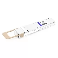
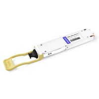
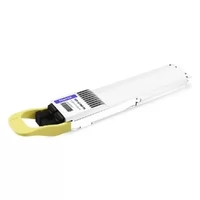
Our production AI cluster had just upgraded to 800G OSFP links. The testing results showed complete success throughout the day. The three spine switches developed flapping problems when the system reached its maximum capacity during the night. The system experienced six hours of downtime. The OSFP troubleshooting process showed its necessity through an expensive lesson, which proved essential for operations.
Sound familiar? You’re not alone. OSFP transceivers power the highest-density data center networks today. When they fail, they fail fast and cost real money.
The guide provides you with a structured method for identifying the causes of OSFP problems. The guide presents you with actionable procedures to resolve both 400G connection link failures and 800G PAM4 signal debugging challenges.
Quick Diagnosis: OSFP Issue Categories
Most OSFP problems fall into four buckets. Knowing which one you’re dealing with saves hours of random testing.
Physical Layer Issues
These are the most common culprits. The problems occur because of dirty connectors and loose MPO latches and modules that technicians have not properly installed. About 70% of fiber link failures in actual situations happen because of contamination or physical damage.
The majority of these problems can be detected through visual inspection. The process requires specific equipment which includes a 400× magnification fiber scope and appropriate cleaning materials and requires the user to exercise patience.
Configuration Issues
OSFP modules have intelligent features but their operation requires specific conditions. The system encounters daily difficulties because link partners have different FEC settings. The system generates “unsupported module” errors when speed settings do not match the module type. The 800G DR8 standard requires Type-C polarity but your 400G equipment uses Type-B connectors.

Environmental Issues
Heat kills. A fully loaded 32-port 800G switch generates over 1,000 watts of heat. OSFP modules themselves run 12-18 watts each. When intake temperatures climb above 35°C, expect problems.
Compatibility Issues
Third-party modules sometimes get rejected by switches. Firmware version mismatches break detection. Even cable quality matters more at 800G than at 100G.
The OSFP Troubleshooting Flowchart
Step 1: Visual Inspection Checklist
Look at the module first. Check for bent pins on the OSFP edge connector—that 60-pin interface is delicate. Verify the module sits flush in the cage. You should hear the retention clip click when it’s fully seated.
Inspect your MPO connectors next. Dust caps should come off only at insertion time. Use your fiber scope to check end-faces. Any contamination, scratches, or cracks mean cleaning or replacement.
Cable bend radius matters too. Don’t go below 30mm on patch cables. Excessive bending causes micro-cracks and signal degradation.
Step 2: DOM/DDM Analysis
Digital Optical Monitoring tells the real story. Access your switch CLI and pull the DOM readings.
Check temperature first. Anything above 70°C puts you in the danger zone. TX and RX optical power come next—compare against your module’s specification sheet. Bias current reveals laser health; abnormally high numbers indicate aging components.
Watch for error flags. RX-LOS (loss of signal), TX-FAULT (transmitter fault), or MOD-NPWR (module not powered) point to specific problems.
Step 3: Isolation Testing
Swap methodically. Move the suspect module to a known-good port. Try a different cable. Test with a loopback module if you have one.
This step separates module problems from port problems from cable problems. Each test narrows the field.
Step 4: Configuration Verification
Verify FEC settings match on both ends. 400G and 800G OSFP modules require FEC—there’s no negotiating around it. Check port speed configuration against the module’s rated speed. Review your vendor’s Hardware Compatibility List if you’re using third-party optics.
Common OSFP Problems and Solutions
These five issues account for roughly 90% of the OSFP troubleshooting calls I see.
Problem 1: Module Not Detected
Your switch CLI shows nothing. Or worse, it shows “unsupported module.”
First, reseat the module. Remove it completely, check for bent pins, and reinsert until the latch clicks. Give it 10-15 seconds to initialize.
Still nothing? Check your switch firmware. Early production 800G modules often need specific firmware versions. Update both the switch OS and module firmware (tools like mlxfwmanager help here).
Third-party module? Your switch might be blocking it. Some vendors require special commands to enable unsupported transceivers. Cisco needs service unsupported-transceiver. Other platforms have similar workarounds.
Problem 2: Link Won’t Come Up
The module shows up, but the interface stays down.
Start with the basics. Verify cable type matches the module—SR8 needs multimode fiber, DR8 needs single-mode. Check that fiber runs haven’t exceeded maximum distance.
Polarity is the sneaky culprit for 800G links. DR8 requires Type-C polarity. Type-A or Type-B configurations that worked for 400G will cause hard failures at 800G. The lane mapping is completely different.
FEC mismatches cause this too. Both ends must agree on FC-FEC or RS-FEC. Check logs for “Logical mismatch between link partners” errors.
Problem 3: Link Flapping
The link comes up, then drops, then comes up again. maddening.
Loose MPO connections are the usual suspects. Those latches can work themselves free in vibrating environments or under cable strain. Verify strain relief is properly installed.
Thermal throttling causes flapping too. When modules hit temperature limits, they shut down to protect themselves. Check DOM temperature readings during the flap—if you’re seeing 70°C+ spikes, you’ve found your problem.
Marginal optical power creates intermittent issues. Clean connectors and measure insertion loss. Anything above 0.35dB per connection at 800G is trouble.
Problem 4: High FEC Errors
Pre-FEC error counters climbing? That’s your early warning system.
Dirty connectors are the most common cause. Even microscopic contamination reflects signal back into the transmitter, causing errors. Clean everything and re-test.
Bend radius violations matter more at 800G than lower speeds. Check your cable routing. Micro-bends from improper installation cause signal degradation that shows up as FEC corrections.
APC vs UPC mismatch creates reflections too. Single-mode OSFP modules require APC polish on MPO connectors. Connecting APC to UPC destroys your link budget with reflections.
Problem 5: Thermal Throttling
High temperatures degrade laser performance and shorten module lifespan.
Check your data center cooling first. OSFP modules in poorly ventilated racks run 10-15°C hotter than spec. Ensure adequate front-to-back airflow. Remove any blanking panels that might block intake air.
Module placement matters. A fully loaded 800G switch runs hot. The modules in the center rows often see the highest temperatures. Consider spreading high-power modules across different switches if possible.
For persistent thermal issues, review your OSFP thermal management strategy. IHS vs RHS heatsink selection makes a real difference. Also consider your broader OSFP data center deployment strategy—cable routing and airflow planning prevent many thermal problems before they start.
Advanced 800G OSFP Issues
800G brings new challenges that don’t exist at lower speeds.
Polarity Troubleshooting (Type-C Required)
Here’s what trips up even experienced engineers: 800G DR8 uses a different polarity scheme than 400G.
The 800G DR8 module maps 8 TX and 8 RX lanes in adjacent pairs. Fiber 1 is TX, fiber 2 is RX, fiber 3 is TX, and so on. Type-C polarity flips each adjacent pair so TX connects to RX on the remote end.
Type-A (straight-through) or Type-B (reversed) won’t work. You’ll get a hard link failure every time.
Verify polarity with a visual fault locator or continuity tester. Label your cables clearly—”Type-C only” saves future headaches.
PAM4 Signal Integrity Issues
800G OSFP uses PAM4 modulation—four signal levels instead of two. This packs more data into the same bandwidth but creates new failure modes.
PAM4 is sensitive to noise and jitter. Poor cable quality that worked fine at 400G NRZ may fail at 800G PAM4. Look for pre-FEC errors climbing while post-FEC errors stay low—that’s your signal integrity canary.
Eye diagram testing helps here, but most network engineers don’t have $50K signal integrity analyzers. Use BER (Bit Error Rate) testing as a practical alternative. Any pre-FEC BER above 1×10⁻⁶ needs investigation.
MPO-16 Connector Problems
OSFP connector types vary by application. SR8 can use dual MPO-12 or single MPO-16. DR8 typically uses MPO-16 for single-mode.
MPO-16 is less forgiving than MPO-12. The ferrule alignment is more critical, and contamination affects more fibers at once. Always inspect with a fiber scope before installation.
Gender matters too. Male connectors (with pins) mate with female connectors (without pins). Mixing these up damages the ferrule and destroys the connector.
Using DOM/DDM for Proactive Monitoring
Don’t wait for failures. Monitor continuously.
Critical Parameters to Monitor
Track these DOM readings:
| Parameter | Normal Range | Critical Threshold | Action |
| Temperature | 30-60°C | >70°C | Check cooling immediately |
| TX Power | Per module spec | max | Replace module |
| RX Power | Per module spec | Near sensitivity limit | Check fiber/clean connectors |
| Bias Current | Baseline ±20% | >150% of baseline | Module aging—plan replacement |
| Voltage | 3.1-3.5V | <3.0V or >3.6V | Power supply issues |
Setting Alert Thresholds
Most switches support DOM threshold alerts. Configure them.
Set temperature warnings at 65°C and critical alarms at 70°C. Configure TX power alerts at ±3dB from nominal. RX power alerts should trigger near the receiver sensitivity limit plus 3dB margin.
Review alerts weekly. Patterns reveal problems before they cause outages.
Predicting Failures Before They Happen
DOM trends predict failures. A module showing gradually increasing bias current over weeks is failing. TX power declining by more than 1dB suggests laser degradation.
Track these trends. Schedule preventive replacements during maintenance windows instead of emergency swaps at 2 AM.
FAQ
Why is my OSFP showing “unsupported module”?
Your switch firmware is blocking third-party modules. Try updating firmware or enabling unsupported transceiver mode in your switch configuration.
What temperature is too hot for OSFP modules?
70°C is the critical threshold. Most modules throttle or shut down above this. Ideally, keep them below 60°C for long-term reliability.
How do I verify MPO polarity?
Use a visual fault locator or continuity tester. For 800G DR8, you need Type-C polarity. The keyway position determines polarity type—check cable labeling or test with a polarity tester.
Can I hot-swap OSFP modules?
Yes. OSFP modules support hot-swapping. But always follow your vendor’s guidelines. Some platforms require specific sequences to avoid port errors.
Conclusion
OSFP troubleshooting doesn’t have to be guesswork. Follow the systematic approach: inspect visually, check DOM readings, isolate the problem, verify configuration.
The expensive failures—the ones that cost $50K and CTO calls—usually come from skipping the basics. Dirty connectors, wrong polarity, or thermal issues that DOM monitoring would have caught days earlier.
Your action items this week:
- Audit your current OSFP deployments. Check DOM readings and establish baseline thresholds.
- Verify your cable polarity, especially for any 800G links. Label everything clearly.
- Review thermal management. Measure intake temperatures at your densest switches.
Need help with a specific OSFP issue? Our engineering team has seen most of these problems before. Contact us for troubleshooting support or browse our 800G OSFP modules for compatible replacements.
Related Products:
-
 NVIDIA MMA4Z00-NS400 Compatible 400G OSFP SR4 Flat Top PAM4 850nm 30m on OM3/50m on OM4 MTP/MPO-12 Multimode FEC Optical Transceiver Module
$400.00
NVIDIA MMA4Z00-NS400 Compatible 400G OSFP SR4 Flat Top PAM4 850nm 30m on OM3/50m on OM4 MTP/MPO-12 Multimode FEC Optical Transceiver Module
$400.00
-
NVIDIA MMS4X00-NS400 Compatible 400G OSFP DR4 Flat Top PAM4 1310nm MTP/MPO-12 500m SMF FEC Optical Transceiver Module
$450.00
-
NVIDIA MMA1Z00-NS400 Compatible 400G QSFP112 VR4 PAM4 850nm 50m MTP/MPO-12 OM4 FEC Optical Transceiver Module
$385.00
-
NVIDIA MMS1X00-NS400 Compatible 400G NDR QSFP112 DR4 PAM4 1310nm 500m MPO-12 with FEC Optical Transceiver Module
$500.00
-
NVIDIA MMA4Z00-NS Compatible 800GBASE 2 x SR4/SR8 OSFP PAM4 850nm 100m DOM Dual MPO-12 MMF Optical Transceiver Module
$550.00
-
NVIDIA MMA4Z00-NS-FLT Compatible 800GBASE 2 x SR4/SR8 OSFP RHS/Flat Top PAM4 850nm 100m DOM Dual MPO-12 MMF Optical Transceiver Module
$600.00
-
NVIDIA MMS4X00-NM Compatible 800GBASE 2 x DR4/DR8 OSFP IHS/Closed Finned Top PAM4 1310nm 500m DOM Dual MTP/MPO-12 SMF Optical Transceiver Module
$600.00
-
NVIDIA MMS4X00-NM-FLT Compatible 800GBASE 2 x DR4/DR8 OSFP Flat Top PAM4 1310nm 500m DOM Dual MTP/MPO-12 SMF Optical Transceiver Module
$650.00
-
NVIDIA MMS4X50-NM Compatible 800G 2x FR4 OSFP IHS/Closed Finned Top PAM4 1310nm 2km DOM Dual Duplex LC SMF InfiniBand NDR Optical Transceiver Module
$1000.00
-
NVIDIA MMS4A00 (980-9IAH1-00XM00) Compatible 1.6T 2 x DR4/DR8 OSFP224 PAM4 1311nm 500m IHS/Finned Top Dual MPO-12 SMF Optical Transceiver Module
$1500.00
-
NVIDIA MMS4A50 Compatible 1.6T 2xFR4/FR8 OSFP224 PAM4 1310nm 2km IHS/Finned Top Dual Duplex LC SMF Optical Transceiver Module
$1800.00
-
NVIDIA MMS4A00-RHS Compatible 1.6T 2xDR4/DR8 OSFP224 PAM4 1311nm 500m RHS/Flat Top Dual MPO-12/APC InfiniBand XDR SMF Optical Transceiver Module
$2000.00