With the accelerated development of the Internet, cloud computing and big data industries, 100G optical module products are being used increasingly widely, and the demand for long-distance transmission has boosted. The traditional solutions rely on using DWDM equipment to increase transmission distance, which has complex networking, requires additional equipment costs and higher maintenance costs; while using 100G QSFP28 ER4 or QSFP 100G ER4 Lite optical modules can simplify the transmission networks, reduce the use of relay equipment and lower the maintenance costs.
Regarding many people may not be clear about the difference between the 100G QSFP28 ER4 and QSFP28 ER4 Lite optical modules, FiberMall will give you a detailed introduction.
1) What is 100G QSFP28 ER4-Lite Optical transceiver?
1. 100G QSFP28 ER4-Lite optical module introduction
The 100G QSFP28 ER4 Lite optical module is a hot-pluggable QSFP28 form module with dual LC interfaces and has an operating temperature of 0°C to 70°C (commercial grade), and a maximum rate of up to 111.8Gbps. The central wavelengths of the 4 LAN WDM channels are 1295.56, 1300.05, 1304.58 and 1309.14 nm as members of the LAN WDM wavelength grid defined in IEEE 802.3ba.
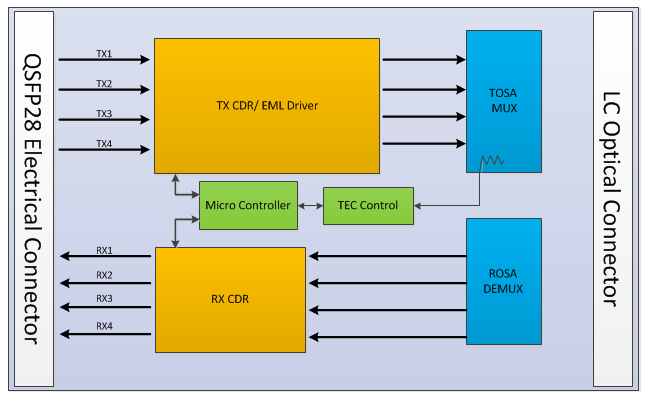
Transceiver Block Diagram
The high-performance cooled LAN WDM EA-DFB transmitters and high sensitivity APD receivers provide superior performance for 100Gigabit Ethernet applications up to 30km links without FEC and 40km links with FEC. The wavelength transmitter Tosa of LAN WDM must be equipped with TEC (Thermo Electric Cooler) to stabilize the wavelength, which will consume about 0.5W extra power while stabilizing the wavelength. Therefore, the power consumption of the LWDM4 optical module is higher than that of CWDM4.
Optical Characteristics
Parameter Symbol Min Typical Max Units Notes
Lane Wavelength L0 1294.53 1295.56 1296.59 nm
L1 1299.02 1300.05 1301.09 nm
L2 1303.54 1304.58 1305.63 nm
L3 1308.09 1309.14 1310.19 nm
Transmitter
SMSR SMSR 30 dB
Total Average Launch Power PT 10.5 dBm
Average Launch Power, PAVG -2.9 4.5 dBm 1
each Lane
OMA, each Lane POMA 0.1 4.5 dBm 2
Difference in Launch Power between any Two Lanes (OMA) Ptx,diff 3.6 dB
Launch Power in OMA minus Transmitter and Dispersion Penalty (TDP), each Lane -0.65 dBm
TDP, each Lane TDP 2.5 dB
Extinction Ratio ER 7 dB
RIN20OMA RIN -130 dB/Hz
Optical Return Loss Tolerance TOL 20 dB
Transmitter Reflectance RT -12 dB
Average Launch Power OFF Transmitter, each Lane Poff -30 dBm
Eye Mask{X1, X2, X3, Y1, Y2, Y3} {0.25, 0.4, 0.45, 0.25, 0.28, 0.4}
Receiver
Damage Threshold, each Lane THd -3 dBm 3
Average Receive Power, each Lane -16.9 -4.9 dBm for 30km Link Distance
Average Receive Power, each Lane -20.9 -4.9 dBm for 40km Link Distance
Receive Power (OMA), each Lane -1.9 dBm
Receiver Sensitivity (OMA), each Lane SEN1 -14.65 dBm for BER = 1x10-12
Stressed Receiver Sensitivity (OMA), each Lane -12.65 dBm for BER = 1x10-12
Receiver Sensitivity (OMA), each Lane SEN2 -18.65 dBm for BER = 5x10⁻⁵
Stressed Receiver Sensitivity (OMA), each Lane -16.65 dBm for BER = 5x10⁻⁵
Receiver reflectance -26 dB
Difference in Receive Power between any Two Lanes (Average and OMA) Prx,diff 3.6 dB
LOS Assert LOSA -26 dBm
LOS Deassert LOSD -24 dBm
LOS Hysteresis LOSH 0.5 dB
Receiver Electrical 3 dB upper Cutoff Frequency, each Lane Fc 31 GHz
Conditions of Stress Receiver Sensitivity Test (Note 4)
Vertical Eye Closure Penalty, each Lane 1.5 dB
Stressed Eye J2 Jitter, each Lane 0.3 UI
Stressed Eye J9 Jitter, each Lane 0.47 UI
2. Special function: Forward Error Correction (FEC)
To increase transmission rate and extend transmission distance are two important trends of optical modules, but with the increase of transmission rate, the signal transmission distance will be limited by many factors, such as Chromatic Dispersion, Nonlinear Effects, Polarization Mode Dispersion, etc. These factors will limit the simultaneous increase of transmission rate and transmission distance. To reduce the impact of these adverse factors, industry experts put forward FEC (forward error correction).
FEC is an error correction technique that solves the problem in optical signal transmission when part of the optical signal at the transmitting end is scrambled during transmission, resulting in a misjudgment at the receiving end. Forward Error Correction (FEC) is used in 100G and other high-speed optical modules. Generally speaking, when this function is turned on, the transmission distance of the high-speed optical module will be longer.
Most switches with 100G QSFP28 ports have Forward Error Correction (FEC). The transmission distance can reach 40km when the FEC is turned on, while when it is turned off, the transmission distance can only reach 30km. 100G optical modules are generally with Forward Error Correction (FEC). Although FEC has two advantages which are correcting forward errors and increasing transmission distance, it will inevitably cause some packet delay in the process of error correction, so not all high-speed optical modules are recommended to open this function. For example, when using the 100G QSFP28 LR4 optical module, it is not recommended to turn on the FEC function.
2) What is 100G QSFP28 ER4 Optical transceiver?
1. 100G QSFP28 ER4 optical module introduction
The 100G QSFP28 ER4 optical module is designed for 100GBASE Ethernet with a transmission rate of up to 40km over single-mode fiber (SMF) via duplex LC connectors. The central wavelengths of the 4 LAN WDM channels are 1295.56, 1300.05, 1304.58 and 1309.14 nm as members of the LAN WDM wavelength grid defined in IEEE 802.3ba. The high-performance cooled LAN WDM EA-DFB transmitters and high sensitivity APD receivers provide superior performance for 100Gigabit Ethernet applications up to 40km links.
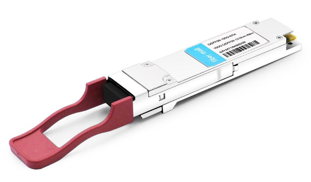
100G QSFP28 ER4 40km
2. 100G QSFP28 ER4 optical module compatibility
The QSFP28 ER4 optical modules are compliant with QSFP MSA, IEEE 802.3ba, 100GBASE-ER4 and OTU4 standards. They’re widely used in 100G Ethernet (100GBASE-ER4) and OTU4 optical transport networks in data centers. The 100G QSFP28 ER4 optical transceiver provided by FiberMall can be compatible with Cisco, Brocade, Arista Networks, Juniper Networks, HW and many other brands of switches.
3. How does100G QSFP28 ER4 optical module works
The transmitter of 100g qsfp28 Er4 optical module can work in four LAN WDM bands of 1295.56nm, 1300.05nm, 1304.58nm and 1309.14nm. The optical signals on these four bands are multiplexed by an LWDM wavelength division multiplexer and transmitted over single-mode fiber(SMF) via industry-standard LC connectors. In addition, SOA can amplify the signal at the receiving end before WDM decomposes the signal into a single channel.
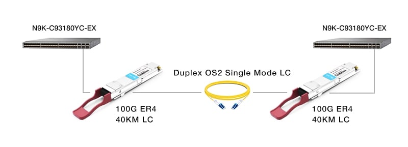
4. 100G QSFP28 ER4 Optical Module-Switching Solutions
Take Cisco nexus 9300 EX Series switches as an example, it is mainly used in data centers and large industrial areas. It has high-density 100GE / 40GE / 25GE / 10GE ports, can be matched with 100G QSFP28 ER4 optical module, OS2 jumper and G.652 SMF. It can help enterprises and operators build a data-center network platform for the era of Cloud Computing.
3) Summary
Above is the introduction of 100G QSFP 100G ER4 Lite and QSFP28 ER4 optical modules. FiberMall’s 100G QSFP28 ER4/ER4-Lite optical modules have high reception sensitivity, low power consumption, and high reliability, which can help users eliminate the cost of using relay optical fiber amplifiers and provide a low-cost solution for long-distance applications of 100GE ports between server rooms. Moreover, FiberMall can also provide 100G QSFP28 ZR4 optical modules, which will save your operating costs by achieving long-distance transmission of 80km without using additional optical amplification relay equipment.
Related Products:
-
 QSFP28-100G-ER4L 100G QSFP28 ER4 Lite 1310nm (LAN WDM) 40km with FEC,30km without FEC LC SMF DDM Transceiver Module
$800.00
QSFP28-100G-ER4L 100G QSFP28 ER4 Lite 1310nm (LAN WDM) 40km with FEC,30km without FEC LC SMF DDM Transceiver Module
$800.00
-
Cisco QSFP-100G-ER4L-S Compatible 100G QSFP28 ER4 Lite1310nm (LAN WDM) 40km with FEC,30km without FEC LC SMF DDM Transceiver Module
$800.00
-
Arista Networks QSFP-100G-ERL4 Compatible 100G QSFP28 ER4 Lite 1310nm (LAN WDM) 40km with FEC, 30km without FEC LC SMF DDM Transceiver Module
$800.00
-
Brocade 100G-QSFP28-ER4-40KM Compatible 100G QSFP28 ER4 Lite 1310nm (LAN WDM) 40km with FEC, 30km without FEC LC SMF DDM Transceiver Module
$800.00
-
Juniper Networks QSFP-100G-ER4L Compatible 100G QSFP28 ER4 Lite 1310nm (LAN WDM) 40km with FEC, 30km without FEC LC SMF DDM Transceiver Module
$800.00
-
QSFP28-112G-ER4 112G OTU4 QSFP28 ER4 1310nm (LAN WDM) 40km LC SMF DDM Transceiver Module
$1300.00