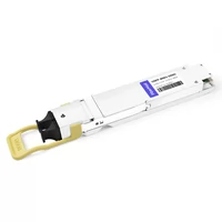
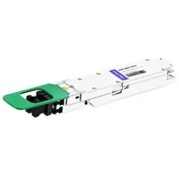
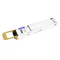
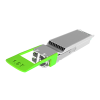
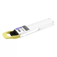
The troubleshooting sessions that caused me the most frustration during data center deployments occurred when I had to solve problems that required technical knowledge about advanced routing protocols and switch configurations. The testing process required connectors. The new 800G link failed to establish a connection because of incorrect MPO cable polarity, incompatible polish type, and incorrect ordering of MPO-12 instead of MPO-16 cables.
The OSFP connector system requires two steps for operation, which include module installation and fiber connection. The actual situation consists of multiple elements that need to be examined. The connector you select today for 400G installation determines your future capability to move to 800G and 1.6T without destroying your existing fiber infrastructure. The incorrect connector specification results in project delays that exceed two weeks, together with extra expenses and physical layer testing work, which requires using a fiber scope while crawling on the floor.
This guide includes all OSFP connector types, which you will find in the document, starting from the 60-pin host edge connector and ending with MPO-16 and MPO-12 fiber interfaces. The training will provide essential specifications for your network calculations, together with the deployment failure compatibility requirements and the process of selecting suitable connectors.
For a comprehensive overview of OSFP technology, see our Complete Guide to OSFP Transceivers.

OSFP Connector Overview
The OSFP Octal Small Form-Factor Pluggable system operates using two separate connector systems which include an electrical edge connector that connects to switches or NICs and an optical connector that connects to fiber cables. The successful implementation requires knowledge of both components.
OSFP Host Interface (60-Pin Edge)
The host-side connector is a 60-pin edge interface that plugs into OSFP cages on switches and network interface cards. This connector carries all electrical signals between the host device and the transceiver module.
Pin Configuration:
- 8 transmit lanes (Tx0-Tx7): Each lane carries 50 Gbps (400G mode) or 100 Gbps (800G mode)
- 8 receive lanes (Rx0-Rx7): Matching receive lanes for full-duplex operation
- Management interface: 2-wire CMIS (Common Management Interface Specification) for module monitoring and control
- Power: 3.3V supply with current draw up to 4.5A for high-power modules
- Ground: Multiple ground pins for signal integrity
The 60-pin connector is physically keyed with an asymmetric shape that prevents upside-down insertion. Unlike earlier form factors, OSFP modules cannot be forced into QSFP-DD ports—the physical dimensions and keying are completely different.
Optical Connector Options
OSFP modules support multiple optical connector types depending on the reach and technology:
MPO (Multi-fiber Push-On): The standard for parallel optics where each lane uses a separate fiber.
- MPO-12: 12-fiber connector (standard for 400G and below)
- MPO-16: 16-fiber connector (native 800G support)
- MPO-24: 24-fiber connector (high-density applications)
Duplex LC: Used for CWDM and coherent optics where multiple wavelengths travel on a single fiber pair.
- LC Duplex: Standard two-fiber connector
- Dual LC: Four fibers for 2×400G breakout configurations
CS Connector: A compact single-pair connector gaining traction for 800G coherent optics where space is at a premium.
Key Specifications
Form Factor Dimensions:
- Width: 22.5 mm (vs 18.4 mm for QSFP-DD)
- Depth: 107.8 mm including connector
- Height: 8.5 mm (flat top) or 10.5 mm (finned top with heatsink)
Power Handling:
- Standard OSFP: Up to 15W
- OSFP-XD: Up to 33.5W for high-power coherent optics
For detailed thermal management guidance, refer to our OSFP Thermal Management Guide.
Port Density:
- Standard 1RU switch: Up to 36 OSFP ports (14.4 Tbps)
MPO-16 vs MPO-12: The Complete Comparison
The choice between MPO-16 and MPO-12 is the most consequential connector decision for OSFP deployments. It affects fiber utilization, migration paths, and infrastructure costs.
Technical Specifications
| Specification | MPO-12 | MPO-16 |
| Fiber Count | 12 fibers | 16 fibers |
| Active Fibers | 8 (4 TX + 4 RX) | 16 (8 TX + 8 RX) |
| Unused Fibers | 4 (center positions) | None |
| Lane Support | 4 lanes native | 8 lanes native |
| Connector Width | Standard MPO | 33% wider |
| Key Position | Standard | Different key (incompatible) |
| Standard | IEC 61754-7 | IEC 61754-7-3 |
Physical Incompatibility: The MPO-12 and MPO-16 connectors require an adapter because their key positions different from each other make direct connection impossible. The system has been designed to prevent errors because users need to understand their infrastructure requirements.
When to Use MPO-16
MPO-16 is the right choice for native 800G and 1.6T deployments where maximum fiber efficiency and density are priorities.
Use MPO-16 for:
- Native 800G SR8/DR8: Single connector for all 8 lanes
- AI cluster backbones: Maximum density for GPU interconnects
- Greenfield data centers: No legacy infrastructure to constrain design
- 1.6T preparation: Future-proof for next-generation speeds
- High-density environments: Limited cabinet space for fiber management
MPO-16 Applications:
- 800G SR8: Multimode, 850nm, up to 100m
- 800G DR8: Single-mode, 1310nm, 500m
- 800G XDR8: Single-mode, extended reach, 2km
- 1.6T SR8: Emerging multimode standard
When to Use MPO-12
MPO-12 remains viable for 400G deployments and migration scenarios where existing infrastructure must be preserved.
Use MPO-12 for:
- 400G SR4/DR4: Native 4-lane applications
- Legacy infrastructure: Existing MPO-12 cable plants
- Cost-sensitive deployments: Lower cable costs and more supplier options
- Dual-MPO-12 800G: NVIDIA twin-port modules (2×400G breakout)
- Gradual migration: Breakout cables to existing leaf switches
Cost Considerations:
- MPO-12 cables: $65-120 for 30m OM4 trunk
- MPO-16 cables: $95-160 for 30m OM4 trunk (46-50% premium)
- MPO-12 suppliers: ~40% more options than MPO-16
OSFP Connector Types by Module
Different OSFP transceiver variants use different connectors depending on their optical technology and target distance. Here is the complete matrix.
400G OSFP Connectors
| Module Type | Connector | Fiber Type | Distance | Application |
| 400G SR4 | MPO-12 APC | MMF OM4/OM5 | 100m | Intra-rack, short reach |
| 400G SR8 | MPO-16 APC | MMF OM4/OM5 | 100m | Higher density alternative |
| 400G DR4 | MPO-12 APC | SMF OS2 | 500m | Leaf-spine, building links |
| 400G FR4 | Duplex LC | SMF OS2 | 2km | Campus interconnect |
| 400G LR4 | Duplex LC | SMF OS2 | 10km | Metro applications |
For detailed 400G deployment guidance, see our 400G OSFP Implementation Guide.
400G Notes:
- SR4 uses 4 lanes (4×100G), requiring 8 fibers (4 TX + 4 RX)
- SR8 uses 8 lanes (8×50G), requiring 16 fibers
- DR4 is the most common single-mode 400G connector
800G OSFP Connectors
| Module Type | Connector | Fiber Type | Distance | Application |
| 800G SR8 | MPO-16 APC or Dual MPO-12 | MMF OM4/OM5 | 100m | AI clusters, intra-DC |
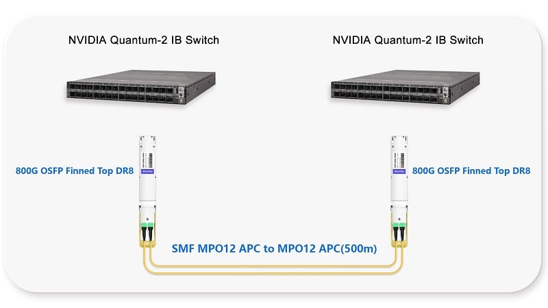
| 800G DR8 | MPO-16 APC | SMF OS2 | 500m | Spine-to-spine |
| 800G 2×DR4 | Dual MPO-12 APC | SMF OS2 | 500m | Breakout to 400G |
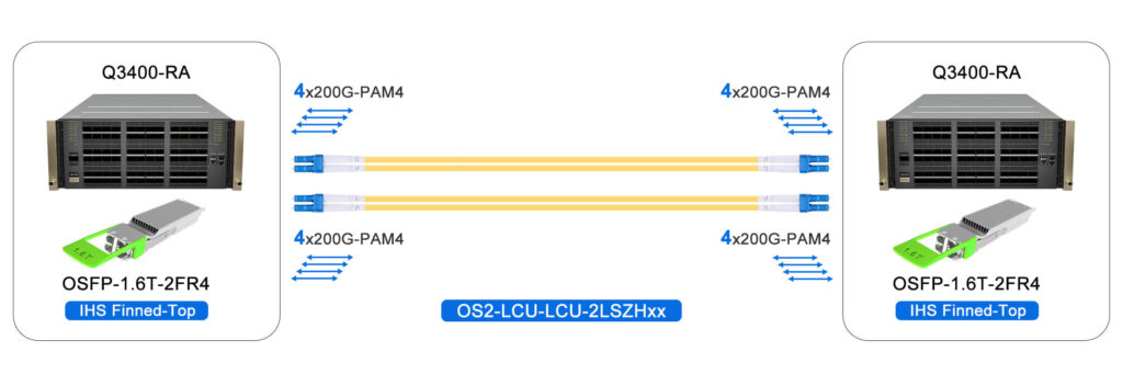
| 800G 2×FR4 | Dual LC Duplex | SMF OS2 | 2km | Campus DCI |
| 800G XDR8 | MPO-16 APC | SMF OS2 | 2km | Extended reach |
800G Notes:
- Native 800G requires MPO-16 (or dual MPO-12 for breakout)
- NVIDIA MMA4Z00-NS uses dual MPO-12 for 2×400G
- Type-C polarity required for DR8 lane alignment
1.6T OSFP-XD Connectors
| Module Type | Connector | Fiber Type | Distance | Notes |
| 1.6T SR8 | MPO-16 APC | MMF OM5 | 100m | Emerging AI standard |
| 1.6T 2×DR4 | Dual MPO-12 APC | SMF OS2 | 500m | Split across two engines |
| 1.6T 2×FR4 | Dual LC/CS | SMF OS2 | 2km | CWDM on duplex fiber |
| 1.6T ZR | LC Duplex | SMF OS2 | 80km | Coherent long-haul |
| 1.6T ZR+ | LC Duplex | SMF OS2 | 480km+ | Extended coherent reach |
1.6T Notes:
- OSFP-XD is 20% larger volume than standard OSFP
- Supports up to 33.5W for high-power coherent optics
- MPO-16 remains standard for parallel multimode
Polarity: Method A, B, and C Explained
The most frequent cause of link failures in MPO deployments occurs because of polarity, which connects transmit fibers with their corresponding receive fibers. Understanding the three polarity methods is essential for correct installation.
Understanding Polarity Methods
Method A (Straight-Through):
- Fiber 1 at one end connects to Fiber 1 at the other end
- Also called “Key Up to Key Down”
- Simplest configuration, used primarily with cassettes
- Not suitable for native 800G parallel optics
Method B (Crossover):
- Fiber 1 at one end connects to Fiber 12 (or 16) at the other end
- The entire ribbon is reversed end-to-end
- Also called “Key Up to Key Up”
- Standard for 400G/800G parallel optics
- Ensures TX lanes connect to RX lanes correctly
Method C (Pair-Flipped):
- Adjacent pairs are swapped (1↔2, 3↔4, 5↔6, etc.)
- Rarely used for parallel optics
- Occasionally seen in duplex serial applications with cassettes
- Not recommended for 800G native connections
Method B for 800G
For 800G parallel optics, Method B is the universal standard. The lane mapping requires that transmit lanes on one end connect to receive lanes on the other:
800G SR8/DR8 Lane Mapping:
- TX1 → RX1, TX2 → RX2, through TX8 → RX8
- Method B polarity achieves this by reversing the entire fiber ribbon
- Any other polarity method results in TX-to-TX or wrong lane connections
Critical for MPO-16: Method B ensures proper alignment of all 8 lanes. Using Method A or C with 800G will cause link failures or partial lane operation.
Testing and Verification
Before Connecting:
- Visual Inspection: Verify key position and fiber numbering on cable labels
- Polarity Tester: Use MPO tester to verify fiber mapping matches Method B
- Documentation: Confirm all cables in the link use the same polarity method
Common Polarity Errors:
- Mixing Method A patch cords with Method B trunk cables
- Assuming all MPO cables use the same polarity
- Using legacy Method C infrastructure with new 800G modules
Troubleshooting: If a link shows activity on some lanes but not others, polarity mismatch is the likely cause. Use a polarity tester or swap to a known-good Method B cable. For comprehensive troubleshooting guidance, see our OSFP Troubleshooting Guide.
APC vs UPC: Polish Requirements
The end-face polish of fiber connectors significantly impacts return loss—the amount of light reflected back toward the source. At 800G speeds, this matters more than at lower data rates.
APC for Single-Mode (Mandatory)
APC (Angled Physical Contact):
- Angle: 8-degree angled polish
- Return Loss: ≥60 dB (0.0001% reflection)
- Color Code: Green connector housing
- Requirement: Mandatory for single-mode 400G/800G/1.6T
Why APC is Required:
- Minimizes back reflections that interfere with signal integrity
- 800G PAM4 signaling is more sensitive to reflections than NRZ
- Prevents ghost signals that can confuse receiver circuits
- Industry standard for all single-mode high-speed optics
UPC for Multimode
UPC (Ultra Physical Contact):
- Surface: Flat polish with slight curvature
- Return Loss: ≥50 dB (0.001% reflection)
- Color Code: Blue connector housing
- Usage: Acceptable for multimode SR8 applications
Multimode Considerations:
- Multimode fiber has higher modal dispersion that tolerates reflections better
- 850nm wavelengths are less sensitive to return loss than 1310nm
- UPC is acceptable for SR8, though APC is still preferred
- Many data centers standardize on APC for all fiber to simplify inventory
The APC/UPC Incompatibility
Never mix APC and UPC in the same link:
- The 8-degree angle of APC creates an air gap when mated with flat UPC
- Results in >3 dB insertion loss (50% signal loss)
- Can damage connector end-faces
- Causes immediate link failure
Visual Identification:
- Green = APC (single-mode, high-speed)
- Blue = UPC (multimode, legacy)
- Beige = MMF multimode (older installations)
Verification Protocol:
Always inspect connector color before mating. When in doubt, use a fiber microscope to verify the angled polish of APC connectors.
Breakout Configurations
One of OSFP’s key advantages is flexible breakout support—an 800G port can connect to multiple lower-speed devices. This enables migration strategies and equipment interoperability.
800G to 2×400G Breakout
Configuration:
- 800G OSFP to two 400G QSFP112 or OSFP modules
- Cable: MPO-16 to 2×MPO-12 breakout
- Lane mapping: Lanes 1-4 → first 400G, Lanes 5-8 → second 400G
Use Cases:
- Connecting 800G spine switches to 400G leaf switches
- Migrating from 400G to 800G incrementally
- Interoperability between switch generations
Examples:
- NVIDIA ConnectX-7: 800G port to two 400G connections
- Arista 7060X5: 800G to 400G breakout support

800G to 4×200G Breakout
Configuration:
- 800G OSFP to four 200G FR4 modules
- Cable: MPO-16 to 4×Duplex LC breakout
- Fiber mapping: Pairs of lanes to each 200G connection
Use Cases:
- Connecting to existing 200G infrastructure
- High-density server connectivity
- Storage network integration
800G to 8×100G Breakout
Configuration:
- 800G DR8 to eight 100G DR1 modules
- Cable: MPO-16 to 8×LC simplex or 4×LC duplex
- Maximum fan-out for mixed environments
Use Cases:
- Maximum compatibility with existing 100G infrastructure
- Lab environments with mixed equipment
- Gradual migration scenarios
Migration Strategies
| Scenario | Approach | Cable Type | Considerations |
| New 800G fabric | Native MPO-16 | MPO-16 trunks | Maximum density, future-proof |
| Mixed 400G/800G | Breakout at spine | MPO-16 to 2×MPO-12 | Preserves leaf investment |
| Existing MPO-12 plant | Breakout cables | MPO-16 to MPO-12 adapters | Temporary solution |
| High-density requirement | All MPO-16 | MPO-16 throughout | Simplified cable management |
Selection Guide
Choosing the right OSFP connector depends on your deployment scenario, existing infrastructure, and future plans.
New Deployment Guide
For 400G networks:
- Short reach (<100m): MPO-12 SR4
- Medium reach (<500m): MPO-12 DR4
- Long reach (<2km): Duplex LC FR4
For 800G networks:
- Short reach: MPO-16 SR8 (native) or Dual MPO-12 (breakout)
- Medium reach: MPO-16 DR8
- Breakout scenarios: Dual MPO-12
For 1.6T networks:
- Parallel multimode: MPO-16 SR8
- Breakout: Dual MPO-12 for 2×800G
- Coherent: Duplex LC or CS for ZR/ZR+
Migration Scenarios
From 100G/400G to 800G:
- Audit existing MPO-12 infrastructure
- Determine breakout requirements at spine layer
- Deploy MPO-16 for new 800G connections
- Use breakout cables for 800G-to-400G connectivity
Preserving Investment:
- Use MPO-16 to 2×MPO-12 breakout cables
- Maintain existing MPO-12 patch panels at leaf layer
- Upgrade to native MPO-16 when leaf switches refresh
Cost Considerations
Cable Costs (30m OM4):
- MPO-12: $65-120
- MPO-16: $95-160 (46-50% premium)
Total Cost of Ownership:
- Factor in cabinet real estate (density matters)
- Consider supplier availability (MPO-16 has fewer options)
- Plan for breakout cable costs during migration
Recommendation: For greenfield 800G deployments, the MPO-16 premium is justified by density and future-proofing. For gradual migrations, factor breakout cable costs into TCO analysis. For data center architecture guidance, refer to our OSFP Data Center Deployment Guide.
FAQ
Q: Can I use MPO-12 cables with 800G OSFP modules?
The 800G SR8/DR8 standard requires MPO-16 connectors, which contain 16 fibers to support 8 data lanes. The NVIDIA MMA4Z00-NS 800G module uses two MPO-12 connectors as its interface, which shows up as two separate 400G ports. To connect 800G switches with 400G systems, use MPO-16 to 2×MPO-12 breakout cables.
Q: What polarity method should I use for 800G?
A: All 800G parallel optics need Method B (crossover) polarity. Method B ensures proper transmit-to-receive lane mapping. Methods A and C will cause link failures or partial lane operation.
Q: Is APC polish required for 800G multimode?
APC is mandatory for single-mode 800G (DR8, FR8). For multimode SR8, UPC is technically acceptable, but APC is recommended for consistency and better performance. Never combine APC and UPC on a single connection.
Q: What is the difference between OSFP and OSFP-XD?
A: OSFP-XD (eXtra Dense) is a larger variant designed for 1.6T and high-power coherent optics. The system exists with 20% additional volume capacity, which enables power handling of 33.5W while the standard OSFP handles 15W power dissipation. OSFP-XD uses the same MPO-16 and LC connectors.
Q: Can I connect OSFP to QSFP-DD ports?
A: No. OSFP and QSFP-DD are physically incompatible. The two systems require different form factors, keying, and port spacing. Adapter cables exist for QSFP28 to OSFP, but not for QSFP-DD to OSFP.
Conclusion
The OSFP connectors function as basic physical links, but their selection creates vital infrastructure choices that determine your capacity to progress from 400G to 800G and 1.6T. Your selection of MPO-12 or MPO-16, together with your chosen polarity method and polish type, will determine whether your fiber plant enables continuous operation or restricts performance.
The future-proof standard for 800G and higher deployments requires new installations to use MPO-16 together with Method B polarity and APC polish. The existing infrastructure allows organizations to use breakout cables and dual-MPO-12 modules as migration paths because these options enable organizations to make gradual upgrades while protecting their investments.
Planning serves as the essential requirement for success. The process requires you to document your connector standards and check polarity before installation and use a fiber scope to examine every connection point. The time spent on these details prevents the physical layer failures that turn simple upgrades into weeks of troubleshooting.
Ready to specify OSFP connectors for your network? Contact FiberMall for expert consultation on OSFP transceivers, MPO cables, and complete fiber connectivity solutions.
Related Products:
-
 NVIDIA MMA4Z00-NS400 Compatible 400G OSFP SR4 Flat Top PAM4 850nm 30m on OM3/50m on OM4 MTP/MPO-12 Multimode FEC Optical Transceiver Module
$400.00
NVIDIA MMA4Z00-NS400 Compatible 400G OSFP SR4 Flat Top PAM4 850nm 30m on OM3/50m on OM4 MTP/MPO-12 Multimode FEC Optical Transceiver Module
$400.00
-
NVIDIA MMS4X00-NS400 Compatible 400G OSFP DR4 Flat Top PAM4 1310nm MTP/MPO-12 500m SMF FEC Optical Transceiver Module
$450.00
-
NVIDIA MMA1Z00-NS400 Compatible 400G QSFP112 VR4 PAM4 850nm 50m MTP/MPO-12 OM4 FEC Optical Transceiver Module
$385.00
-
NVIDIA MMS1X00-NS400 Compatible 400G NDR QSFP112 DR4 PAM4 1310nm 500m MPO-12 with FEC Optical Transceiver Module
$500.00
-
NVIDIA MMA4Z00-NS Compatible 800GBASE 2 x SR4/SR8 OSFP PAM4 850nm 100m DOM Dual MPO-12 MMF Optical Transceiver Module
$550.00
-
NVIDIA MMA4Z00-NS-FLT Compatible 800GBASE 2 x SR4/SR8 OSFP RHS/Flat Top PAM4 850nm 100m DOM Dual MPO-12 MMF Optical Transceiver Module
$600.00
-
NVIDIA MMS4X00-NM Compatible 800GBASE 2 x DR4/DR8 OSFP IHS/Closed Finned Top PAM4 1310nm 500m DOM Dual MTP/MPO-12 SMF Optical Transceiver Module
$600.00
-
NVIDIA MMS4X00-NM-FLT Compatible 800GBASE 2 x DR4/DR8 OSFP Flat Top PAM4 1310nm 500m DOM Dual MTP/MPO-12 SMF Optical Transceiver Module
$650.00
-
NVIDIA MMS4X50-NM Compatible 800G 2x FR4 OSFP IHS/Closed Finned Top PAM4 1310nm 2km DOM Dual Duplex LC SMF InfiniBand NDR Optical Transceiver Module
$1000.00
-
NVIDIA MMS4A00 (980-9IAH1-00XM00) Compatible 1.6T 2 x DR4/DR8 OSFP224 PAM4 1311nm 500m IHS/Finned Top Dual MPO-12 SMF Optical Transceiver Module
$1500.00
-
NVIDIA MMS4A50 Compatible 1.6T 2xFR4/FR8 OSFP224 PAM4 1310nm 2km IHS/Finned Top Dual Duplex LC SMF Optical Transceiver Module
$1800.00
-
NVIDIA MMS4A00-RHS Compatible 1.6T 2xDR4/DR8 OSFP224 PAM4 1311nm 500m RHS/Flat Top Dual MPO-12/APC InfiniBand XDR SMF Optical Transceiver Module
$2000.00