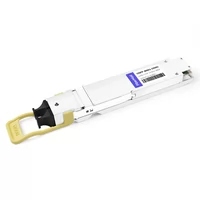
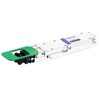
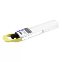
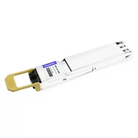
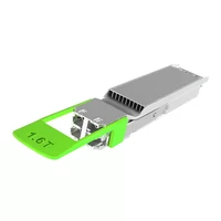
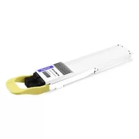
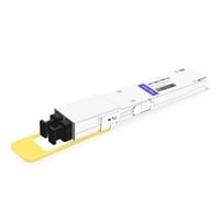
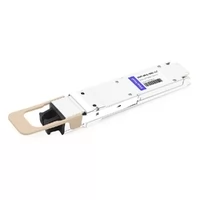
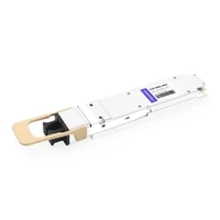
The current speed of AI infrastructure deployment has reached its highest level because hyperscale data centers create an unending need for 800G optical transceivers. Cloud service providers will require 800G transceivers at twice their current shipment rate, which will double their shipment rate 2025, since they need high-speed networks for training large language models and operating GPU clusters.
The 800G OSFP (Octal Small Form-factor Pluggable) transceiver functions as the core element which provides 800 Gbps optical bandwidth through eight 100G PAM4 lanes while maintaining better heat dissipation than other form factor types. Network engineers who build next-generation data center infrastructures must learn how 800G OSFP modules work because these modules define system needs and operational limits.
The complete guide evaluates 800G OSFP standards, which describe different available module types while inspecting thermal behavior and power usage patterns and offering implementation support for AI-based data center operations.
What is 800G OSFP? Technical Overview
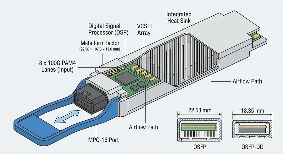
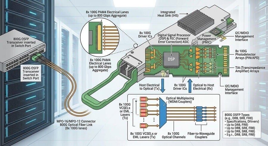
The 800G OSFP optical transceiver module transmits data through optical fiber at a rate of 800 gigabits per second. The “Octal” designation refers to the eight electrical lanes that each carry 100 Gbps using PAM4 (Pulse Amplitude Modulation 4-level) signaling, combining to provide the aggregate 800 Gbps data rate.
Form Factor Specifications
The OSFP form factor was purpose-built for high-speed optical applications, featuring dimensions of 22.58 × 107.8 × 13.0 millimeters. The design uses physical dimensions that exceed the size of QSFP-DD, which measures 18.35 × 89.4 × 8.5 millimeters, to solve thermal problems that occur during 800G transmission.
Key technical specifications include:
| Specification | Details |
| Data Rate | 800 Gbps (8 × 106.25 Gbps lanes) |
| Electrical Interface | 800GAUI-8 |
| Modulation | PAM4 (53 Gbaud) |
| Power Supply | 3.3V single rail |
| Management Interface | CMIS 5.0/5.1 |
| Operating Temperature | 0°C to 70°C (commercial grade) |
The OSFP MSA (Multi-Source Agreement) establishes the mechanical and electrical and thermal requirements which enable different manufacturers’ modules to work together. The 800GBASE Ethernet implementations of IEEE 802.3ck standards provide performance standards which all industry players must follow.
Why OSFP for 800G?
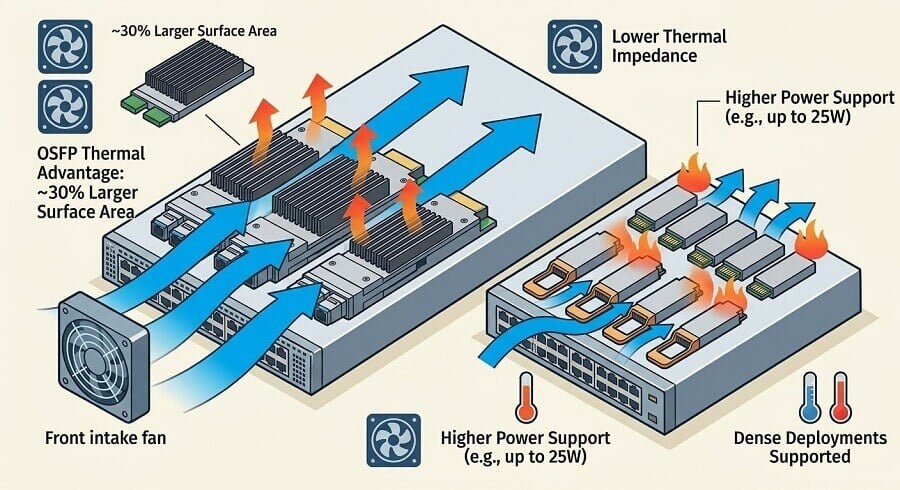
The transition from 400G to 800G optical modules presents significant engineering challenges which engineers must solve through their work on power dissipation and thermal management problems. The 800G optical transceiver needs between 15 and 20 watts of power which means it requires almost twice as much energy as the 400G module. The larger OSFP form factor provides approximately 30% more surface area for heat dissipation compared to QSFP-DD, enabling reliable operation at these higher power levels.
This thermal advantage becomes critical in dense switch configurations. A fully populated 32-port 800G switch generates approximately 480–640 watts from optics alone, plus an additional 300–400 watts from the switch ASIC. The OSFP form factor enables data center operators to handle their challenging thermal loads through its advanced thermal design, which eliminates the need for complex cooling systems.
800G OSFP Types and Specifications
The 800G OSFP transceivers operate according to three different criteria, which include their transmission distance, fiber type, and optical technology. The different types of equipment provide solutions that meet distinct connectivity needs that exist between data center rooms and between different buildings.

800G OSFP SR8: Short-Reach Multimode
The SR8 (Short Range) module provides high-density connectivity for short-distance connections between adjacent racks. The system operates at 850nm using VCSEL (Vertical Cavity Surface Emitting Laser) technology with multimode fiber, which serves as the most economical solution for 800G optical transmission.
Technical Specifications:
- Wavelength: 850nm
- Fiber Type: OM3, OM4, or OM5 multimode fiber
- Maximum Distance: 30m (OM3), 50m (OM4), 100m (OM5)
- Connector: MPO-16 or dual MPO-12 APC
- Power Consumption: <15W
- Laser Type: VCSEL array
The SR8 modules show their best performance when used for intra-rack and adjacent-rack deployments because these situations require high port density but operate within short distance ranges. The 850nm VCSEL technology uses established manufacturing processes, which produce high volumes of products to achieve the most affordable 800G optical solution at a cost of one gigabit. The system requires less than 15 watts of power, which helps to control heat build-up in areas with high equipment density.
The system connects servers to Top-of-Rack switches while creating storage array connections and establishing connections between high-density GPU clusters that operate in adjacent rack spaces.
800G OSFP DR8: Data Center Reach
The DR8 (Data Center Reach) module functions as the main operational component, which enables 800G optical connections to work at distances up to 500 meters through single-mode fiber. The system uses 1310nm EML technology, which features Electro-absorption Modulated Laser components as its primary 800G solution for artificial intelligence clusters and cloud computing systems.
Technical Specifications:
- Wavelength: 1310nm
- Fiber Type: OS2 single-mode fiber
- Maximum Distance: 500 meters
- Connector: MPO-12 APC
- Power Consumption: 16–18W
- Laser Type: EML or Silicon Photonics
The 500-meter reach of DR8 modules covers the vast majority of data center interconnect scenarios, from leaf-to-spine connections to pod-to-pod interconnects within the same facility. The distance sweet spot between 50 and 300 meters matches current data center architectural standards for rack spacing.
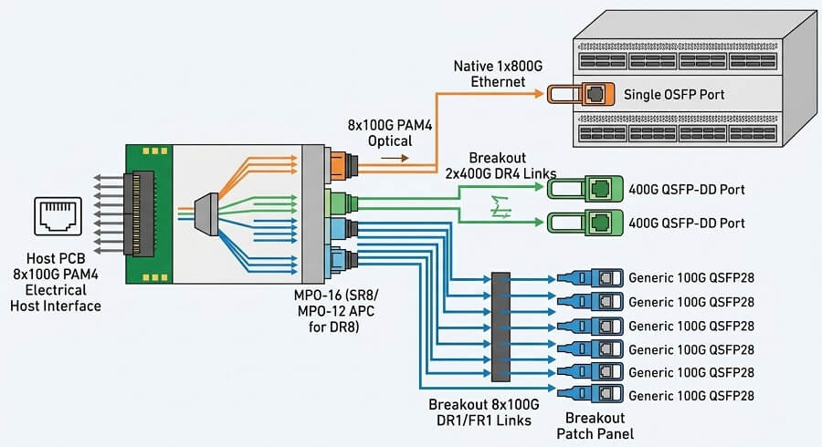
A defining characteristic of DR8 modules is their breakout flexibility. The eight-lane architecture can be configured as:
- 1×800G: Native 800G operation
- 2×400G: Two independent 400G DR4 links
- 8×100G: Eight 100G DR1 links
This breakout capability enables seamless migration from existing 400G or 100G infrastructure without requiring hardware replacement, protecting investment in fiber plant and switch hardware.
800G OSFP FR8: Extended Reach
The FR8 (Longer Reach) module extends connectivity to 2 kilometers using CWDM (Coarse Wavelength Division Multiplexing) technology. It addresses scenarios where DR8’s 500-meter reach is insufficient but long-haul coherent optics would be excessive.
Technical Specifications:
- Wavelength: 1310nm CWDM8
- Fiber Type: OS2 single-mode fiber
- Maximum Distance: 2 kilometers
- Connector: Duplex LC or dual CS
- Power Consumption: 16–18W
- Laser Type: CWDM EML array
FR8 modules achieve substantial fiber count reductions when compared to DR8 because they transmit eight 100G lanes through two fibers, which contain eight wavelengths. The fiber efficiency of this system functions as an essential resource for campus environments and distributed data centers and locations with limited fiber duct space.
The main trade-off between the two options requires higher expenses and more complex systems than DR8. The production of CWDM optics demands advanced techniques for manufacturing and alignment, which leads to elevated costs for each module. When fiber resources become limited, decreased fiber usage results in major financial advantages for the entire project.
800G OSFP Type Comparison
| Specification | SR8 | DR8 | FR8 |
| Distance | 100m | 500m | 2km |
| Fiber Type | MMF (OM4/OM5) | SMF (OS2) | SMF (OS2) |
| Fiber Count | 16 fibers | 16 fibers | 2 fibers |
| Wavelength | 850nm | 1310nm | 1310nm CWDM |
| Connector | MPO-16 | Dual MPO-12 APC | Duplex LC |
| Typical Power | <15W | 16–18W | 16–18W |
| Relative Cost | Low | Medium | High |
800G OSFP vs QSFP-DD: Key Differences
Network architects evaluating 800G optical modules face a fundamental choice between two competing form factors: OSFP and QSFP-DD. The two systems enable 800G transmission, yet they exhibit different physical design elements, thermal performance capabilities, and system compatibility attributes.
Form Factor and Physical Dimensions
The most immediate difference is physical size. OSFP modules are approximately 23% wider and 20% taller than QSFP-DD modules:
| Dimension | OSFP | QSFP-DD |
| Width | 22.58 mm | 18.35 mm |
| Length | 107.8 mm | 89.4 mm |
| Height | 13.0 mm | 8.5 mm |
This larger footprint gives OSFP modules substantially greater surface area for heat dissipation—a critical advantage given the thermal challenges of 800G optics.
Thermal Management Capabilities
OSFP and QSFP-DD systems differ most significantly because their thermal performance serves as their primary distinguishing feature. The OSFP form factor enables installation of larger heat sinks, which improve airflow to support equipment operation at higher power levels.
Power Handling Comparison:
- OSFP: Supports modules up to 20–25W
- QSFP-DD: Typically limited to 17–18W
This thermal headroom becomes particularly important for:
- Coherent optics: 800G ZR/ZR+ modules require 20W+
- High-power DSP implementations: Some 800G designs approach power limits
- Dense deployments: Full 32-port switches with high-power optics
Data center engineers report that OSFP’s integrated heat sink design (IHS variants) provides more predictable thermal performance compared to QSFP-DD’s reliance on switch cage thermal interfaces.
Backward Compatibility
The backward compatibility of QSFP-DD provides it with a major competitive edge. The “Double Density” design maintains the same physical width as QSFP28/QSFP56 modules, which enables QSFP-DD ports to accept legacy modules through suitable adapters. This system safeguards current 100G and 400G optical investments throughout infrastructure enhancements.
OSFP does not provide backward compatibility to QSFP-series modules. OSFP ports only support OSFP modules, but users can use mechanical adapters to connect QSFP-DD modules to OSFP ports (electrical compatibility depends on switch support).
This compatibility consideration heavily influences upgrade strategies:
- QSFP-DD preferred: Organizations upgrading from existing QSFP28/QSFP56 infrastructure
- OSFP preferred: Greenfield deployments or AI-focused infrastructure where backward compatibility is less critical
Port Density and Switch Capacity
Despite the larger module size, both form factors achieve identical port density in modern switch designs:
- Ports per 1RU: 36 ports (14.4 Tbps total capacity)
- Ports per 2RU: 64 ports (25.6 Tbps total capacity)
Switch silicon from leading vendors (Broadcom, Cisco Silicon One, Marvell) supports both form factors at full density, meaning the form factor choice does not constrain overall switch capacity.
Selection Guidelines
Choose 800G OSFP when:
- Building AI/ML training clusters with high-power requirements
- Deploying 800G ZR/ZR+ coherent optics for DCI
- Planning for future 1.6T upgrades (OSFP roadmap extends to 1.6T and beyond)
- Operating in thermally challenging environments
- Implementing greenfield hyperscale infrastructure
Choose 800G QSFP-DD when:
- Upgrading from existing QSFP28/QSFP56 infrastructure
- Maximizing compatibility with the installed base of modules
- Operating in space-constrained environments where every millimeter matters
- Running standard 800G SR8/DR8 optics with moderate power requirements
Power Consumption and Thermal Management
Power consumption and thermal management represent the most critical deployment considerations for 800G OSFP infrastructure. The 800G deployment success depends on understanding thermal calculations and selecting proper cooling methods that protect system reliability.
Real-World Power Consumption
While datasheets typically cite 15–18W for standard 800G OSFP modules, real-world deployments often see higher consumption:
| Module Type | Datasheet Typical | Real-World Range |
| SR8 | 12–15W | 13–16W |
| DR8 | 15–18W | 16–20W |
| FR8 | 16–18W | 17–21W |
| ZR/ZR+ | 18–22W | 20–25W |
Factors affecting actual power draw include:
- Temperature: Higher ambient temperatures increase laser bias current
- Fiber conditions: Poor connections or long fibers increase the transmit power
- FEC overhead: Forward Error Correction processing adds DSP power
- Vendor implementation: Different optical engine designs vary in efficiency
Thermal Math for Switch Deployments
Calculating total thermal load is essential for data center planning. Consider a fully populated 32-port 800G switch:
| Component | Power per Unit | Quantity | Total Power |
| 800G DR8 Optics | 18W | 32 | 576W |
| Switch ASIC | 400W | 1 | 400W |
| System Overhead | 100W | 1 | 100W |
| TOTAL | 1,076W |
Over one kilowatt in a 1RU or 2RU chassis presents significant cooling challenges. At 1,076W with 2RU (88mm) height, the power density exceeds 12 kW per rack unit—demanding careful thermal design.
Cooling Requirements
Maintaining reliable operation requires adhering to specific environmental parameters:
Airflow Requirements:
- Minimum velocity: 3–4 meters per second across module heat sinks
- Intake temperature: <25°C recommended (<35°C maximum)
- Rack clearance: Minimum 6 inches front and rear for adequate airflow
- Air mixing prevention: Hot aisle/cold aisle containment is essential
OSFP Heat Sink Options:
- Finned-top (IHS): Integrated heat sink with vertical fins for air-cooled switches
- Flat-top (RHS): Reduced height for liquid-cooled or constrained environments
The choice between finned-top and flat-top variants depends on the switch platform and cooling architecture. Finned-top modules generally provide superior cooling performance in air-cooled environments.
Impact on Data Center PUE
The heightened energy requirements of 800G optical systems have a direct impact on data center Power Usage Effectiveness (PUE) calculations. The total power consumption of optical modules needs about 1.2 to 1.5 times more facility power when cooling requirements are factored in.
For large-scale deployments, this power penalty drives interest in emerging technologies like Linear-drive Pluggable Optics (LPO) and Co-Packaged Optics (CPO) that promise significant power reductions:
- LPO 800G: <8W (approximately 50% reduction)
- CPO: 3.5× power efficiency improvement (future technology)
800G OSFP Applications and Use Cases
800G OSFP transceivers serve diverse applications across modern data center and networking environments, with AI infrastructure currently driving the strongest demand growth.
AI/ML Training Clusters
The quick rise of generative AI technology has created an extraordinary need for network links that provide high data transmission speeds and minimal delay times between GPU servers. AI training clusters now use 800G OSFP modules as their standard equipment.
Key Requirements:
- Bandwidth: 800 Gbps per link supporting NDR (Next Data Rate) InfiniBand
- Latency: Sub-microsecond latency for RDMA (Remote Direct Memory Access)
- Reliability: 24/7 operation during multi-week training runs
NVIDIA’s Quantum-2 InfiniBand switches and Spectrum-X Ethernet platforms both support OSFP modules, with many configurations defaulting to OSFP due to thermal requirements. The DR8 module breakout feature enables users to connect ConnectX-7 network interface controllers, which support both 400G and 200G data rates.
Typical AI cluster configurations use:
- DR8 modules: For leaf-to-spine and GPU-to-switch connections
- Breakout cables: 800G to 2×400G for flexible NIC connectivity
- Fat-tree topologies: Maximizing bisection bandwidth for all-to-all communication
Hyperscale Cloud Data Centers
Cloud providers deploying 800G infrastructure prioritize scalability, reliability, and operational efficiency. OSFP’s thermal advantages support dense, high-availability architectures required at hyperscale.
Deployment Patterns:
- Spine-leaf architectures: 800G links between spine and leaf switches
- Clos networks: Non-blocking connectivity for massive scale
- Modular building blocks: Standardized pods replicating across facilities
The major cloud providers AWS, Azure, Google Cloud, and Meta currently deploy 800G OSFP infrastructure, according to industry analysts who predict 800G will become the standard for new data center construction starting in 2025.
High-Performance Computing (HPC)
Computational scientific work and simulation tasks need continuous high-speed data transfer between their processing units. High-performance computing facilities first used 100G and 400G network connections, but now upgrade their systems to 800G technology.
HPC-Specific Considerations:
- MPI workloads: Message Passing Interface applications demand consistent latency
- Parallel file systems: High-bandwidth storage access
- Topology optimization: Dragonfly, torus, or fat-tree networks customized for workload patterns
Data Center Interconnect (DCI)
The 800G coherent OSFP modules use ZR/ZR+ technology to connect remote sites at distances between 80 and 120 kilometers. The modules use the OSFP form factor together with coherent optical DSPs to create data center links that handle high capacity without requiring regeneration.
DCI Applications:
- Campus connectivity (FR8 for <2km)
- Metro area networks (ZR for 80km)
- Regional interconnects (ZR+ for 120km+)
Breakout Configurations and Flexibility
The main advantage of 800G OSFP modules over other features is their ability to divide one 800G port into multiple lower-speed links. This capability protects infrastructure investments and enables gradual migration strategies.
1×800G Native Operation
In native mode, the 800G OSFP module operates as a single 800 Gbps link. This configuration maximizes bandwidth per port and minimizes cabling complexity for pure 800G environments.
Use Cases:
- 800G switch-to-switch links
- Direct connection to 800G-capable NICs
- High-bandwidth storage interconnects
2×400G Breakout
The most common breakout configuration splits an 800G port into two independent 400G links. This enables connection to existing 400G infrastructure and supports the transition from 400G to 800G networks.
Implementation:
- Optical breakout cables: MPO-16 to dual MPO-12
- Passive splitters: Optical signal division without active components
- Independent operation: Each 400G link operates autonomously
Applications:
- Migration from 400G to 800G switches
- Connection to ConnectX-7 NICs at 400G
- Maximizing port utilization during transition periods
8×100G Breakout
For maximum flexibility, 800G OSFP modules can break out to eight 100G links. This configuration bridges to legacy 100G infrastructure and enables high-fan-out topologies.
Implementation:
- Breakout cables: MPO-16 to 8×LC duplex
- Patch panel distribution: Centralized fiber management
- Mixed-speed environments: Supporting diverse endpoint requirements
Cable and Connectivity Options
Selecting appropriate cables is critical for 800G OSFP deployments:
| Cable Type | Application | Distance | Characteristics |
| DAC (Direct Attach Copper) | Intra-rack | <3m | Lowest cost, lowest latency |
| AOC (Active Optical Cable) | Intra-row | <100m | Pre-terminated, plug-and-play |
| Breakout AOC | Mixed-speed | <100m | 800G to 2×400G or 8×100G |
| Structured Fiber | Full facility | <500m | Custom lengths, MPO connectors |
Deployment Best Practices
Successful 800G OSFP deployment requires attention to compatibility, infrastructure preparation, and operational procedures.
Switch and Platform Compatibility
Verify switch platform support before procurement. Leading switch vendors offering OSFP support include:
- Arista: 7060X5, 7800R3 series with OSFP variants
- Cisco: 8100 series and select Nexus platforms
- Juniper: PTX10000 and QFX10000 series
- NVIDIA: Quantum-2 InfiniBand, Spectrum-X Ethernet
- Marvell-based: Various white-box switch options
Critical Verification Points:
- CMIS 5.0/5.1 management interface support
- Forward Error Correction (FEC) mode compatibility
- Breakout configuration support (if required)
- Thermal design validation for planned density
Fiber Infrastructure Requirements
800G OSFP modules place stringent requirements on fiber infrastructure:
Multimode (SR8):
- OM4 minimum: Supports 50m at 800G
- OM5 recommended: Extends reach to 100m
- MPO-16 connectors: Ensure proper polarity (Type A/B)
Single-mode (DR8/FR8):
- OS2 single-mode: Standard for 1310nm transmission
- APC polish required: MPO-12 APC connectors mandatory
- Cleanliness critical: 800G signal integrity demands pristine fiber
Testing Requirements:
- Tier 1 testing: Insertion loss verification
- Tier 2 OTDR: Fault location and splice verification
- End-face inspection: 400× magnification before connection
Installation and Handling
Proper handling prevents damage to sensitive optical components:
- ESD protection: Use grounded wrist straps during installation
- Dust caps: Keep caps on until immediate connection
- Connector cleaning: Use lint-free wipes and approved solvents
- Insertion force: Apply even pressure; do not force
- Retention verification: Confirm proper latch engagement
Testing and Validation
Post-installation validation ensures proper operation:
Physical Layer Testing:
- Optical power measurement (TX and RX)
- Bit Error Rate (BER) verification
- FEC error monitoring
Performance Validation:
- Throughput testing at line rate
- Latency measurement
- Buffer behavior under load
Future Roadmap: From 800G to 1.6T
The 800G OSFP module represents a transitional technology toward even higher speeds. Understanding the roadmap helps infrastructure planners make future-proof decisions.
1.6T OSFP Development
Industry standards bodies and the OSFP MSA are actively developing 1.6T OSFP specifications. These modules will double the bandwidth again through:
- 16×100G lanes: Doubling lane count from 8 to 16
- 200G lanes: Alternative approach using 8×200G PAM4
- OSFP-XD: Extended-depth variant for additional thermal capacity
Timeline: 1.6T OSFP modules are expected to enter production in 2025–2026, with hyperscale deployments beginning shortly thereafter.
Co-Packaged Optics (CPO)
Looking further ahead, Co-Packaged Optics represents the next major architectural shift. CPO integrates optical engines directly onto switch ASIC packages, eliminating pluggable modules entirely.
CPO Advantages:
- Power reduction: 50%+ improvement over pluggable optics
- Signal integrity: Eliminates PCB trace losses
- Density: Higher bandwidth per rack unit
Timeline: Early CPO deployments expected 2026–2027, with mainstream adoption following in the 2028–2030 timeframe.
Preparing Infrastructure for Evolution
Organizations deploying 800G today can prepare for future transitions:
- Fiber infrastructure: Deploy MPO-16 and high-fiber-count cables
- Thermal design: Plan for 25W+ per module capability
- Space planning: Ensure adequate rack space for future equipment
- Monitoring: Implement comprehensive optical layer monitoring
Conclusion
AI data centers need high-performance networking infrastructure, which has become the standard optical module for their operations. The system delivers dependable 800G transmission performance through its thermal management system, which operates better than QSFP-DD under high power requirements, while its SR8, DR8, and FR8 variant options provide multiple connection solutions.
Key considerations for network architects include:
- Thermal planning is critical: 800G deployments require careful attention to cooling capacity and airflow design
- Module selection depends on distance: SR8 for intra-rack, DR8 for general data center, FR8 for extended reach
- Breakout flexibility protects investment: 800G ports can serve existing 400G and 100G infrastructure during transition periods
- OSFP positions for the future: The form factor’s roadmap extends to 1.6T and beyond
The 800G OSFP transceivers create the optical basis that supports upcoming network technologies as AI infrastructure deployment progresses and hyperscale data centers reach their maximum operational capacity. The 100% year-over-year growth in 800G shipments demonstrates that the industry considers this technology to be the standard solution for high-bandwidth connections needed throughout the next decade.
Ready to deploy 800G OSFP in your data center? FiberMall offers a comprehensive range of 800G OSFP transceivers, including SR8, DR8, and FR8 variants, all MSA-compliant and compatible with major switch platforms. Our optical networking experts can help you design the optimal infrastructure for your AI and high-performance computing requirements.
Related Articles
- [Complete Guide to OSFP Transceivers] — Comprehensive overview of OSFP technology covering 400G, 800G, and 1.6T implementations
- [OSFP vs QSFP-DD: Form Factor Comparison] — Detailed analysis of the differences between OSFP and QSFP-DD form factors
- [1.6T OSFP InfiniBand: Ultra-High-Speed Connectivity] — Exploring the next generation of OSFP technology for AI clusters
- [OSFP Thermal Management Best Practices] — Engineering guidance for managing power and cooling in OSFP deployments
- [OSFP Data Center Deployment Guide] — Architecture and implementation strategies for OSFP infrastructure
Related Products:
-
 NVIDIA MMA4Z00-NS Compatible 800GBASE 2 x SR4/SR8 OSFP PAM4 850nm 100m DOM Dual MPO-12 MMF Optical Transceiver Module
$550.00
NVIDIA MMA4Z00-NS Compatible 800GBASE 2 x SR4/SR8 OSFP PAM4 850nm 100m DOM Dual MPO-12 MMF Optical Transceiver Module
$550.00
-
NVIDIA MMA4Z00-NS-FLT Compatible 800GBASE 2 x SR4/SR8 OSFP RHS/Flat Top PAM4 850nm 100m DOM Dual MPO-12 MMF Optical Transceiver Module
$600.00
-
NVIDIA MMS4X00-NM Compatible 800GBASE 2 x DR4/DR8 OSFP IHS/Closed Finned Top PAM4 1310nm 500m DOM Dual MTP/MPO-12 SMF Optical Transceiver Module
$600.00
-
NVIDIA MMS4X00-NM-FLT Compatible 800GBASE 2 x DR4/DR8 OSFP Flat Top PAM4 1310nm 500m DOM Dual MTP/MPO-12 SMF Optical Transceiver Module
$650.00
-
NVIDIA MMS4X50-NM Compatible 800G 2x FR4 OSFP IHS/Closed Finned Top PAM4 1310nm 2km DOM Dual Duplex LC SMF InfiniBand NDR Optical Transceiver Module
$1000.00
-
NVIDIA MMS4A20-XM800 Compatible 800G DR4 OSFP224 4x200G-PAM4 1311nm 500m RHS/Flat Top DOM MTP/MPO-12 APC InfiniBand XDR Transceiver Module
$1300.00
-
NVIDIA MMS4A00 (980-9IAH1-00XM00) Compatible 1.6T 2 x DR4/DR8 OSFP224 PAM4 1311nm 500m IHS/Finned Top Dual MPO-12 SMF Optical Transceiver Module
$1500.00
-
NVIDIA MMS4X50-NM Compatible 1.6T 2xFR4/FR8 OSFP224 PAM4 1310nm 2km IHS/Finned Top Dual Duplex LC SMF Optical Transceiver Module
$1800.00
-
NVIDIA MMS4A00-RHS Compatible 1.6T 2xDR4/DR8 OSFP224 PAM4 1311nm 500m RHS/Flat Top Dual MPO-12/APC InfiniBand XDR SMF Optical Transceiver Module
$2000.00
-
OSFP-800G-DR8D-FLT Compatible 800GBASE 2 x DR4/DR8 OSFP Flat Top PAM4 1310nm 500m DOM Dual MTP/MPO-12 SMF Optical Transceiver Module
$650.00
-
OSFP-800G-SR8D-FLT Compatible 800G 2 x SR4/SR8 OSFP RHS/Flat Top PAM4 850nm 100m DOM Dual MPO-12 MMF Optical Transceiver Module
$600.00
-
OSFP-800G-SR8D Compatible 800GBASE 2 x SR4/SR8 OSFP PAM4 850nm 100m DOM Dual MPO-12 MMF Optical Transceiver Module
$550.00
-
OSFP-800G-2FR4L 800G 2 x FR4 OSFP IHS/Closed Finned Top PAM4 1310nm 2km DOM Dual Duplex LC SMF InfiniBand NDR Optical Transceiver Module
$1000.00
-
OSFP-800G-DR8D Compatible 800GBASE 2 x DR4/DR8 OSFP PAM4 1310nm 500m DOM Dual MTP/MPO-12 SMF Optical Transceiver Module
$550.00