James examined the switch log. The system showed the error message %SFP-4-UNSUPPORTED_SENSE. He had just spent two days on an RMA process involving twelve QSFP-DD modules that his Cisco Nexus system failed to identify. When the replacement modules arrived, the exact same error occurred. James finally discovered the root cause when a coworker suggested checking the switch firmware: his new CMIS 4.0 modules were incompatible with the switch’s older CMIS 3.0 firmware. The oversight resulted in two days of unproductive work.
The process of effective QSFP-DD troubleshooting determines whether technicians will solve an issue with a quick solution or require a complete weekend for work at the data center. The system requires high precision because there exists a narrow tolerance range for 400G and 800G operations. A filthy MPO connector, together with two components, which include a firmware mismatch and a hot lane creates an error condition that disables a link responsible for transporting all traffic from an entire rack.
This guide provides a structured five-stage troubleshooting system for QSFP-DD, which solves approximately 90 percent of problems without making any assumptions. The system includes specific diagnostic commands for each vendor, together with a DDM interpretation system and an isolation method that stops unnecessary RMAs from occurring. The framework maintains fast and precise diagnostics for both module detection failures and QSFP-DD link flapping cases. If you need background on the technology first, read our complete QSFP-DD guide.
The 5-Phase QSFP-DD Troubleshooting Workflow
Seventy percent of QSFP-DD troubleshooting cases are resolved in Phase 1. If you skip this step, your time will be wasted because you will search for nonexistent issues.
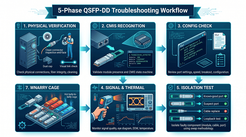
Engineers should verify the physical layer—where the vast majority of failures occur—before moving on to firmware upgrades, configuration checks, and Bit Error Rate (BER) analysis. Completing each phase systematically saves time, avoids unnecessary hardware returns, and achieves faster link stabilization.
| Phase | Focus | Approximate Resolution Rate |
| Phase 1 | Physical Verification | ~40% |
| Phase 2 | Module Recognition & CMIS | ~25% |
| Phase 3 | Configuration Verification | ~15% |
| Phase 4 | Signal Quality, BER & Thermal | ~10% |
| Phase 5 | Isolation Testing | ~10% |
The process requires you to complete each current stage before starting the next one. You need to check physical integrity before proceeding to Phase 2. You need to confirm module recognition and configuration before starting BER analysis in Phase 4. The structured methodology for QSFP-DD troubleshooting prohibits engineers from making random attempts, which result in wasted work hours.
Phase 1: Physical Verification
A seemingly “dead” module often requires nothing more than 30 seconds and a lint-free wipe to restore functionality. Effective troubleshooting always begins with the simplest potential failure points.
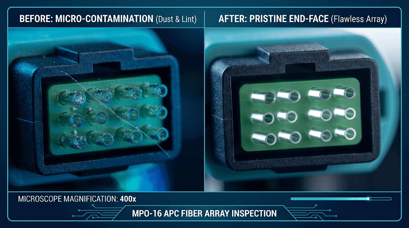
Sarah, a data center technician in Dallas, spent three hours troubleshooting a 400G DR4 link that refused to establish. She verified configurations, updated firmware, and swapped switch ports without success. Finally, after removing the module and inspecting the MPO connector with a fiber microscope, she discovered a single microscopic strand of lint trapped across the fiber array. Cleaning the end-face took 30 seconds, and the link established immediately. The phantom “bad optic” was simply dirty glass.
Visual Inspection Checklist
Start with visual and physical assessments. Most physical layer issues are obvious once you know what to look for:
- Module seating: Push firmly until the latch clicks. Partial insertion is the #1 cause of intermittent lane errors.
- Golden fingers: Check the electrical contacts for corrosion, debris, or bent pins. A single bent pin on lane 3 will break a 400G link.
- Connector damage: Look for cracked ferrules, pulled boots, or kinked cables. 400G MPO-16 connectors are more fragile than MPO-12.
- Dust caps: Modules without dust caps in storage are already contaminated.
Proper cable hygiene is the foundation of effective QSFP-DD troubleshooting. Connector contamination alone accounts for the majority of optical transceiver failures in 400G deployments. For a deeper look at cable types and compatibility, see our QSFP-DD cable guide.
MPO Connector Cleaning Procedure
Connector contamination causes 65-70% of all 400G link failures. In QSFP-DD troubleshooting, the fiber end-face is always worth checking first. At PAM4 modulation, even microscopic debris creates enough loss to close the eye diagram.
- Inspect first: Use a 400× fiber microscope. Look for dust, oil, or debris on the end-face. Never clean what you haven’t inspected.
- Wet-to-dry method: Apply one drop of fiber cleaning fluid to a lint-free wipe. Draw the connector across the wet section, then across a dry section.
- Verify APC polish: 400G QSFP-DD modules use APC (angled physical contact) connectors with an 8° polish angle. If you see a flat blue end-face, that’s UPC. You need green APC connectors.
- Re-inspect: Clean until the end-face passes inspection. A single retry takes 30 seconds. A failed link costs hours.
Cable and Environmental Checks
- Bend radius: Single-mode fiber needs a 30mm minimum bend radius. Tight cable management can induce micro-bending loss — an easy-to-miss variable in QSFP-DD troubleshooting.
- Strain relief: Heavy MPO trunk cables pulling on the module can cause intermittent contact — a subtle but real factor in QSFP-DD troubleshooting that few engineers check first.
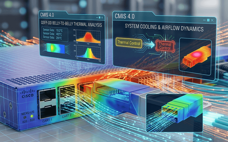
- Airflow and thermal shadowing: In belly-to-belly cage designs, upper-row modules ingest pre-heated air from lower-row exhaust. Upper ports can run 10-15°C hotter. If you’re seeing thermal issues, check our QSFP-DD power guide.
Phase 2: Module Recognition & CMIS
Host switches do not always report module states accurately. “QSFP-DD not detected” is one of the most frequent and frustrating symptoms encountered in the field
The Common Management Interface Specification (CMIS) defines how QSFP-DD transceivers communicate with host switches. Mastering CMIS state transitions is essential for resolving detection issues. CMIS 4.0—the standard for modern 400G/800G optics—introduced complex EEPROM memory maps that older switch firmware cannot properly decode. When this happens, the switch senses the hardware presence but fails to read its operational parameters, resulting in an “unsupported transceiver” flag or total non-detection.
Vendor-Specific Module Detection Commands
Cisco IOS-XR / NX-OS:
show interfaces transceiver
show interfaces transceiver detail
show module
These Cisco commands are foundational to any QSFP-DD troubleshooting effort on IOS-XR or NX-OS platforms.
Arista EOS:
show interfaces Ethernet1/1 transceiver
show interfaces transceiver eeprom
For Arista operators, QSFP-DD troubleshooting starts with checking whether the EEPROM is readable and the module state transitions correctly.
Juniper JunOS:
show chassis hardware
show chassis pic fpc-slot 0 pic-slot 0
These commands should be your first stop in any structured QSFP-DD troubleshooting process.
SONiC / Linux:
show interface transceiver eeprom Ethernet0
ethtool -m Ethernet0
For Linux-based deployments, ethtool -m is an indispensable QSFP-DD troubleshooting command that exposes the full EEPROM memory map.
The module installation requires verification when it fails to show up in the system. The system shows vendor information incorrectly, which indicates a CMIS compatibility problem that represents a common source of CMIS errors within 400G deployments.
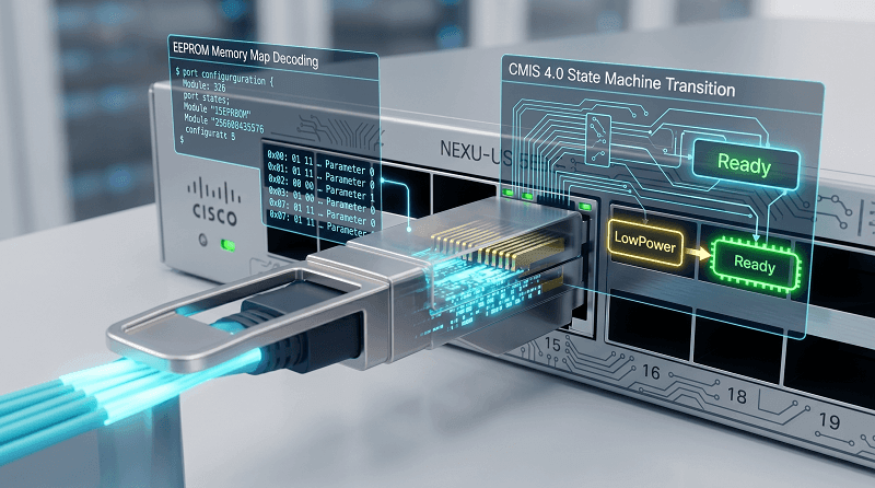
CMIS State Machine Deep-Dive
QSFP-DD modules move through a defined state machine during initialization. In disciplined QSFP-DD troubleshooting, the state machine tells you exactly where to look next.
| State | Description | Common Failure Mode |
| LowPower | Module inserted, minimal power | Power class mismatch |
| PowerUp | Module initializing | Insufficient port power |
| Ready | Module ready for data path | Firmware decode failure |
| Fault | Error condition detected | Hardware failure |
For the data path itself:
| Data Path State | Description | Common Failure Mode |
| Deactivated | No data path active | Port not enabled |
| Init | Data path initializing | Speed/FEC mismatch |
| Activated | Link operational | Should show green |
When a module hangs in Init, the common cause is speed or FEC mismatch between the host and the module. The system will not reach the Ready state because of CMIS version incompatibility, which creates continuous CMIS errors that remain until the firmware is updated.
Vendor Lock-In and Third-Party Modules
OEM switches validate the module’s vendor ID EEPROM field. A third-party module with correct EEPROM coding will work perfectly. A third-party module without vendor-specific coding will fail with errors like:
- Cisco: %SFP-4-UNSUPPORTED_SENSE
- Juniper: Unsupported transceiver
- Arista: Usually detects but logs warnings
When you troubleshoot QSFP-DD systems with third-party optics, platform behaviors become the main factor you need to assess. Optical transceiver failures occur in 99 percent of cases because of firmware compatibility or EEPROM coding issues rather than third-party modules.
Workarounds:
- Cisco: service unsupported-transceiver (hidden command, may void warranty)
- Juniper: Some platforms allow allow-unsupported-transceiver
- Arista: Generally most permissive; third-party optics work without hacks
Resolving CMIS errors and vendor lock-in issues is a core skill in modern QSFP-DD troubleshooting. For more on compatibility, read our QSFP-DD compatibility guide.
Phase 3: Configuration Verification
The link works at 100G but not 400G? Check your FEC.
Modern 400G links depend on Forward Error Correction (FEC) to handle the bit-error rates that PAM4 signaling introduces. FEC mismatches are a frequent culprit in 400G transceiver troubleshooting — if one end has FEC enabled and the other doesn’t, the link either won’t establish or will show massive error counts.
FEC Configuration
400G Ethernet mandates RS-FEC RS(544,514), also known as KP4 FEC. This isn’t optional.
| Parameter | Normal Threshold | Action Required If Exceeded |
| Pre-FEC BER | < 2.4 × 10⁻⁴ | Monitor trend; link still corrects |
| Post-FEC BER | < 1 × 10⁻¹² | Any post-FEC errors = critical |
| Corrected codewords | Stable baseline | Rapid increase = signal degrading |
| Uncorrected codewords | Zero | Non-zero = link will flap |
Common FEC mismatches in 400G transceiver troubleshooting:
- Host FEC enabled, module FEC disabled
- RS-FEC vs FC-FEC type mismatch
- Host-side FEC interfering with module-internal FEC
To check FEC status:
The commands function as necessary components that every 400G transceiver troubleshooting toolkit requires. The test results enable you to determine whether the module shows garbled vendor information or the complete disappearance of vendor information.
Cisco:
show fec event-log
show platform hardware fed active fec statistics
Arista:
show interfaces counters errors
show fec status
SONiC:
show interface counters | grep -i fec
Breakout Configuration
400G QSFP-DD to 4×100G breakout is a common source of confusion. The lane mapping must match between the switch ASIC, the cable, and the remote end.
Standard 400G → 4×100G lane mapping:
- Lane 0-1 → Breakout Port 1
- Lane 2-3 → Breakout Port 2
- Lane 4-5 → Breakout Port 3
- Lane 6-7 → Breakout Port 4
MPO polarity matters. Breakout cables typically use Method B (crossover) polarity. If you see some breakout ports working and others not, polarity is the first suspect in your QSFP-DD troubleshooting process.
For module type specifics that affect breakout, see our guide to 400G QSFP-DD module types.
Port Speed Verification
These commands confirm your port is set to the correct speed — a basic but often overlooked step in 400G transceiver troubleshooting.
| Platform | Command |
| Cisco | show interface status |
| Arista | show interfaces status |
| Juniper | show interfaces terse |
| SONiC | show interface status |
Phase 4: Signal Quality, BER, and Thermal Issues
The Pre-FEC BER trends show that they can identify link failures that will occur 2 to 3 weeks before the links actually stop functioning. The ability to identify optical transceiver failures at their earliest stage enables better decision-making, which results in scheduled replacements instead of emergency outages that occur at 3 AM.
Mike, a network engineer from Phoenix, worked on a difficult problem that involved QSFP-DD link flapping during a new 400G system installation. He performed three DAC replacements. He conducted two replacements of the module. The flapping issue continued to take place. He discovered a known bug that affected that specific DAC part number after checking the switch firmware release notes. The 15-minute firmware update solved the problem that three days of hardware replacements failed to resolve.
DDM Parameter Interpretation
Digital Diagnostic Monitoring (DDM) — also called DOM — gives you real-time telemetry from the module. In advanced QSFP-DD troubleshooting, DDM readings are your earliest warning system. Knowing what’s normal prevents panic.
| Parameter | Normal Range | Warning Sign |
| TX Power | Per module spec (varies by type) | >3dB below spec |
| RX Power | Above receiver sensitivity with margin | Below sensitivity or above overload |
| Temperature | 25-70°C case temp | >70°C warning, >85°C shutdown |
| Laser Bias Current | Stable baseline | >20% increase over baseline |
| Voltage | 3.135-3.465V | Outside range indicates power issue |
The bias current trend is your best early warning in QSFP-DD troubleshooting. A laser that needs 20% more current to maintain the same output power is approaching end-of-life. Replace it during the next maintenance window, not during an outage.
Thermal Shadowing and Belly-to-Belly Cages
The design of dense 1RU switches, which include 32 exterior QSFP-DD ports that connect through belly-to-belly cages, creates actual thermal shadowing which remains unrecognized. The optical transceiver failures that happen through this method create the illusion that their modules are defective.
Lower-row modules exhaust hot air directly into the intake of upper-row modules. When testing different ports, engineers found that upper ports operated 10-15°C hotter than lower ports. The thermal shadowing causes modules to fail at particular port ranges while identical modules in other ranges continue to function normally. This pattern of optical transceiver failure occurs because engineers who examine the system do not take temperature measurements.
Diagnostic approach:
- Compare DOM temperatures across all ports
- Look for temperature clustering by cage row
- Check airflow direction and velocity
- Verify blanking panels are installed in empty slots
- Consider lower-power alternatives (FR4 instead of ZR) for thermally constrained positions
Thermal analysis is a critical dimension of QSFP-DD troubleshooting in high-density switches. For detailed thermal specs, refer to our QSFP-DD power guide.
PAM4 Signal Integrity Basics
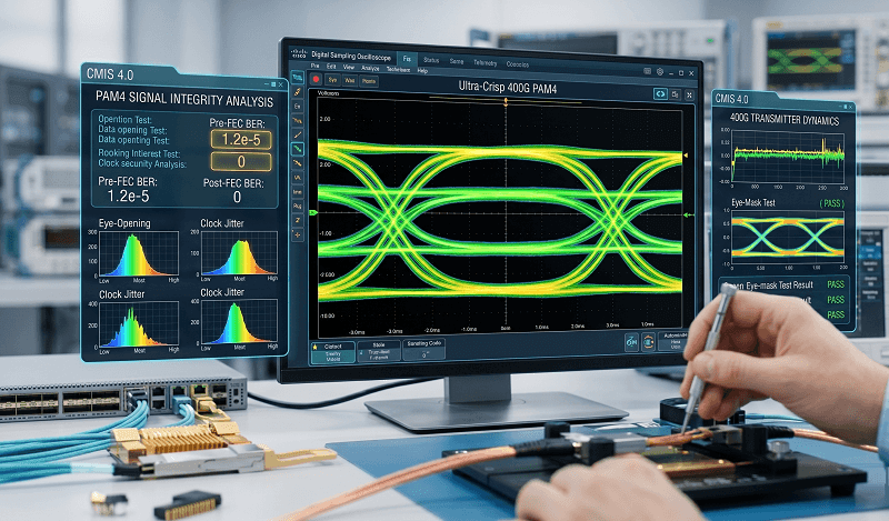
400G and 800G use PAM4 (Pulse Amplitude Modulation with 4 levels) instead of traditional NRZ (Non-Return-to-Zero). PAM4 packs twice the bits per clock cycle but requires significantly better signal quality.
What this means for troubleshooting:
- PAM4 eye diagrams have three eyes instead of one. Any eye closure causes errors.
- Lane-specific errors usually point to host ASIC, electrical interface, or individual optical channel issues.
- Crosstalk between lanes in the same module is more significant at 400G than at 100G.
If you see errors concentrated on specific lanes (e.g., lanes 2 and 3 only), suspect the electrical path between the switch ASIC and the module rather than the optical path. The main pattern that shows advanced QSFP-DD troubleshooting needs to be solved exists through lane-specific errors.
Phase 5: Isolation Testing
Swap the right component, and you’ll know in 30 seconds.
The structured isolation testing process serves as the last stage of QSFP-DD troubleshooting after you have eliminated all physical issues, CMIS problems, configuration problems, and signal quality problems. The testing procedure aims to determine which component among the module, port, cable, and remote end contains the fault.
The Swap Test Decision Tree
Step 1: Module to known-good port
- Move the suspect module to a port that works with a known-good module.
- If the suspect module works → original port or cable is the problem.
- If the suspect module still fails → module is likely faulty.
Step 2: Known-good module to suspect port
- Move a working module to the suspect port.
- If it works → original module is faulty.
- If it fails → port or cable is the problem.
Step 3: Cable replacement
- Replace the cable with a known-good spare.
- If link works → cable was the issue.
- If link still fails → problem is in the port or module.
Step 4: Remote end swap
- If both local tests pass, repeat Steps 1-2 on the remote end.
This four-step sequence isolates the fault in four moves or fewer. Most engineers skip steps or swap multiple components simultaneously, which destroys diagnostic clarity. Patience is a virtue in systematic QSFP-DD troubleshooting.
QSFP-DD Loopback Module Testing
Loopback modules short the TX lanes back to the RX lanes internally. They’re the fastest way to separate host-side issues from fiber-side issues.
When to use a loopback in QSFP-DD troubleshooting:
- Link won’t establish and you need to know if the switch port is healthy
- The remote site is inaccessible and you need local verification
- Suspected host ASIC lane failure
Expected behavior:
- Insert loopback, enable port
- Port should come up immediately (no fiber needed)
- DOM will show high RX power (expected — it’s a short loop)
- BER should be near zero
If the port won’t come up with a loopback, the issue is host-side (ASIC, electrical, or configuration). If it works with loopback but not with a real module, the issue is optical or remote-side. Loopback testing is one of the fastest ways to narrow your QSFP-DD troubleshooting scope.
For environments that need to bridge form factors during QSFP-DD troubleshooting, adapter converter modules can extend your diagnostic toolkit.
QSFP-DD Troubleshooting FAQ
Why is my QSFP-DD not detected?
The first step requires you to check physical seating before proceeding to check firmware compatibility. The QSFP-DD not detected issue occurs because of CMIS version mismatch, which proves the module to be operational. The switch firmware needs to support CMIS 4.0 for QSFP-DD modules to function correctly. The older firmware version cannot decode the EEPROM data because it lacks complete decoding capability. The update process needs to occur before module return authorizations.
My 400G link keeps flapping — what should I check first?
You need to check the MPO polarity. Breakout cables typically use Method B (crossover) polarity. Polarity mismatch exists as the most probable explanation when some lanes function while others remain inoperable. You need to verify lane mapping alignment among switch ASIC, cable, and remote end components.
What steps should I take to resolve my 400G link issue that keeps dropping?
The initial step requires you to examine the physical layer. The QSFP-DD link flapping issue results from connector contamination, loose connector seating, and thermal stress. The process requires you to inspect MPO connectors, clean them, verify module seating, and check DOM temperature trends. The physical checks need to pass before you can check the FEC configuration and firmware version. The majority of flaps become resolved during Phase 1 or Phase 3. The QSFP-DD link flapping issue persists after physical examinations because of a firmware or FEC mismatch.
How do I clean MPO connectors during QSFP-DD troubleshooting?
The first step requires using a 400× fiber microscope to perform an inspection. The process requires applying wet-to-dry cleaning with lint-free wipes and fiber cleaning fluid. The inspection requires you to check both the APC polish and the green connectors, which have an 8° angle. The inspection must proceed before reconnecting the equipment. The inspection step functions as an essential requirement that needs to be followed. The connector cleanliness test represents the most effective method to verify QSFP-DD systems because it detects 90 percent of problems that occur during QSFP-DD tests.
What DDM values should I monitor during QSFP-DD troubleshooting?
The case temperature must remain below 70°C. The TX and RX power levels need to match the specifications established by the module manufacturer. Laser bias current should stay constant because a 20% increase from the standard value signals that the system has reached its end-of-life point. The voltage must show a range between 3.135V and 3.465V.
Can I use third-party QSFP-DD in Cisco switches?
Third-party QSFP-DD devices will function with Cisco switches when you use the correct vendor coding for the EEPROM. The service unsupported-transceiver command needs to be activated by some switches. The warranty protection for that specific port will undergo changes because of this situation. Arista systems demonstrate a more open approach to their users. Vendor lock-in knowledge becomes essential for QSFP-DD troubleshooting in environments that include multiple vendor systems. Users can depend on third-party modules that have correct coding because they function properly, but the main problem arises from CMIS defects and EEPROM compatibility issues instead of hardware quality. For details, see our QSFP-DD compatibility guide.
What’s the difference between pre-FEC and post-FEC BER?
Pre-FEC BER measures raw physical signal quality before error correction. The 400G transmission system experiences typical errors. Post-FEC BER measures remaining errors after Reed-Solomon correction. Any post-FEC errors are critical because they indicate that the noise burst exceeded the FEC’s correction capacity. The complete QSFP-DD troubleshooting process requires both metrics as fundamental data points.
QSFP-DD Troubleshooting: Key Takeaways
James demonstrated his ability to learn from past mistakes by avoiding the same error. After completing his CMIS firmware instruction, he created a pre-deployment checklist that identified three additional compatibility problems that would have been missed until production. The team has developed a solution that enables them to fix 400G link problems within half an hour.
Here’s what to remember from this QSFP-DD troubleshooting guide:
- Seventy percent of QSFP-DD failures are physical layer. Clean connectors, reseat modules, and check cables before you touch a configuration.
- Update firmware before RMAing hardware. CMIS errors from version mismatches and known DAC bugs waste days and shipping costs.
- DDM trends predict failures before they happen. Track laser bias current and temperature. Replace modules showing degradation during planned maintenance, not during outages.
- Use the swap test decision tree. Swap one component at a time. Simultaneous swaps destroy diagnostic clarity.
- Any post-FEC BER is critical. Pre-FEC errors are expected. Post-FEC errors mean your margin is gone.
The rising port densities in AI and HPC cluster systems create increasing difficulties for both thermal management and signal integrity maintenance. The ability to perform complete systematic QSFP-DD troubleshooting from physical layer testing through to CMIS error decoding enables operators to establish active network management processes that act before network problems occur.
If you need replacement modules, loopback test equipment, or compatibility-verified optics for your 400G transceiver troubleshooting toolkit, contact FiberMall. We test every module against major switch platforms before shipment and can pre-code EEPROMs for your specific vendor environment.
Related Products:
-
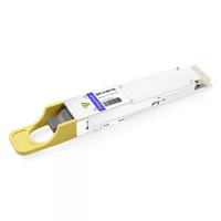
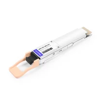
 QSFP-DD-800G-DR8 800G-DR8 QSFP-DD PAM4 1310nm 500m DOM MTP/MPO-16 SMF Optical Transceiver Module
$1000.00
QSFP-DD-800G-DR8 800G-DR8 QSFP-DD PAM4 1310nm 500m DOM MTP/MPO-16 SMF Optical Transceiver Module
$1000.00
-
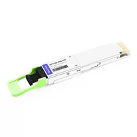
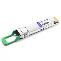
QSFP-DD-800G-FR8 QSFP-DD 8x100G FR PAM4 1310nm 2km DOM MPO-16 SMF Optical Transceiver Module
$1200.00
-
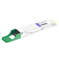
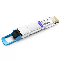
QSFP-DD-800G-2FR4 800G QSFP-DD 2FR4 PAM4 1310nm 2km DOM Dual CS SMF Optical Transceiver Module
$1900.00
-
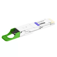
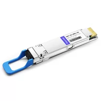
QSFP-DD-800G-2FR4L QSFP-DD 2x400G FR4 PAM4 CWDM4 2km DOM Dual duplex LC SMF Optical Transceiver Module
$1800.00
-
QSFP-DD-800G-DR8D QSFP-DD 8x100G DR PAM4 1310nm 500m DOM Dual MPO-12 SMF Optical Transceiver Module
$1000.00
-
QSFP-DD-800G-FR8L QSFP-DD 800G FR8 PAM4 CWDM8 2km DOM Duplex LC SMF Optical Transceiver Module
$3000.00
-
QSFP-DD-400G-SR8 400G QSFP-DD SR8 PAM4 850nm 100m MTP/MPO OM3 FEC Optical Transceiver Module
$149.00
-
QSFP-DD-400G-DR4 400G QSFP-DD DR4 PAM4 1310nm 500m MTP/MPO SMF FEC Optical Transceiver Module
$400.00
-
QSFP-DD-400G-SR4 QSFP-DD 400G SR4 PAM4 850nm 100m MTP/MPO-12 OM4 FEC Optical Transceiver Module
$450.00
-
QSFP-DD-400G-FR4 400G QSFP-DD FR4 PAM4 CWDM4 2km LC SMF FEC Optical Transceiver Module
$500.00
-
QSFP-DD-400G-XDR4 400G QSFP-DD XDR4 PAM4 1310nm 2km MTP/MPO-12 SMF FEC Optical Transceiver Module
$550.00
-
QSFP-DD-400G-LR4 400G QSFP-DD LR4 PAM4 CWDM4 10km LC SMF FEC Optical Transceiver Module
$600.00
-
QSFP-DD-400G-SR4.2 400Gb/s QSFP-DD SR4 BiDi PAM4 850nm/910nm 100m/150m OM4/OM5 MMF MPO-12 FEC Optical Transceiver Module
$750.00
-
QSFP-DD-400G-ER4 400G QSFP-DD ER4 PAM4 LWDM4 40km LC SMF without FEC Optical Transceiver Module
$3500.00
-
QSFP-DD-400G-ER8 400G QSFP-DD ER8 PAM4 LWDM8 40km LC SMF FEC Optical Transceiver Module
$3800.00
-
QSFP-DD-400G-LR8 400G QSFP-DD LR8 PAM4 LWDM8 10km LC SMF FEC Optical Transceiver Module
$3800.00