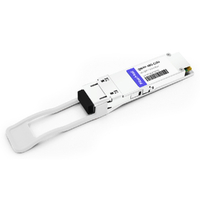
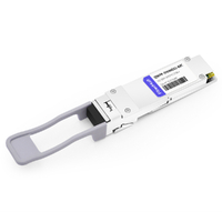
A data center architect told me last month that his team still runs 40G aggregation in every leaf-spine row. I asked why they hadn’t moved to 100G. His answer was simple: the upstream spine was 40G, the servers only needed 10G, and OM4 fiber was already in place. Buying QSFP28 optics would have left them throttled at 40G anyway.
That conversation is exactly why this guide exists. A qsfp+ transceiver isn’t legacy dead weight in 2026. It’s a precision tool for brownfield 40G aggregation, 4×10G breakout, and any network layer where 40G is the real bottleneck. You don’t always need the newest generation. You need the generation that matches the fiber, the port speed, and the budget.
Below, you’ll get a complete variant matrix, a worked port/cable/power example, and a migration checklist that shows when to stay on 40G and when to move to 100G QSFP28. If you already know your fiber type, explore FiberMall’s optical transceiver solutions to compare compatible modules.
What Is a QSFP+ Transceiver?
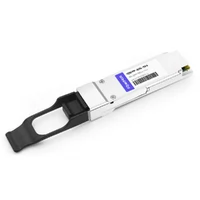
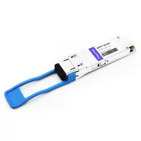
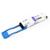
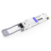
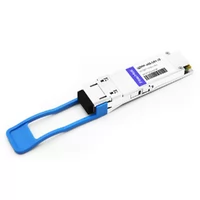
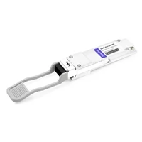
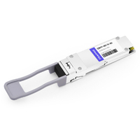
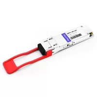
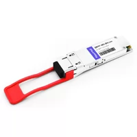
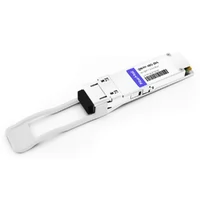
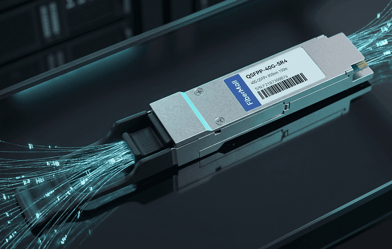
A qsfp+ transceiver is a hot-pluggable optical module that carries four 10 Gbps electrical lanes over a single physical port. QSFP+ stands for Quad Small Form-factor Pluggable Plus. The plus (+) marks the 40G Ethernet generation, not the older 4G QSFP used in Fibre Channel and InfiniBand.
The four lanes are aggregated into a 40 Gbps data transmission rate. The module follows the SFF-8436 mechanical specification and the IEEE 802.3ba 40GBASE family of standards. You can think of it as four SFP+ transceivers sharing one housing, one connector, and one switch port.
QSFP+ ports are common on data center switches, storage controllers, and telecom line cards that need density without jumping to 100G. If you want the full family overview, see our guide to the complete QSFP transceiver family.
QSFP+ Transceiver Variants at a Glance
Not every 40G QSFP+ module is interchangeable. QSFP+ SR4, QSFP+ LR4, QSFP+ ER4, and related variants differ in wavelength, fiber type, connector, transmission distance, optical architecture, and power consumption.
The following table summarizes commonly deployed QSFP+ optical variants. Some products, including CSR4, eSR4, LR4-Lite, PLR4, and PSM4, are vendor-specific or industry-defined implementations rather than universally standardized IEEE interfaces. Their exact specifications should therefore be verified against the manufacturer’s datasheet.
| Variant | Wavelength | Fiber | Connector | Reach | Typical Power | Common Use |
| 40GBASE-SR4 | 850 nm | OM3/OM4 MMF | MPO-12 | OM3 100 m / OM4 150 m | ~1.5 W | Data center top-of-rack |
| 40GBASE-CSR4 | 850 nm | OM4 MMF | MPO-12 | 300–400 m | ~1.5 W | Extended-reach multimode |
| 40GBASE-eSR4 | 850 nm | OM4 MMF | MPO-12 | 300 m (up to 400 m) | ~1.5 W | Longer MMF links |
| 40GBASE-LR4 | 1310 nm CWDM | SMF | LC duplex | 10 km | ~3.5 W | Campus / DCI |
| 40GBASE-LR4-Lite | 1310 nm CWDM | SMF | LC duplex | 2 km | ~3.5 W | Short single-mode spans |
| 40GBASE-ER4 | 1310 nm CWDM | SMF | LC duplex | 40 km | ~3.5 W | Metro / long-haul |
| 40GBASE-PLR4 | 1310 nm parallel | SMF | MPO-12 | 10 km | ~3.5 W | 4×10G breakout over SMF |
| 40GBASE-PSM4 | 1310 nm parallel | SMF | MPO-12 | 2 km | ~3.5 W | 4×10G breakout over SMF |
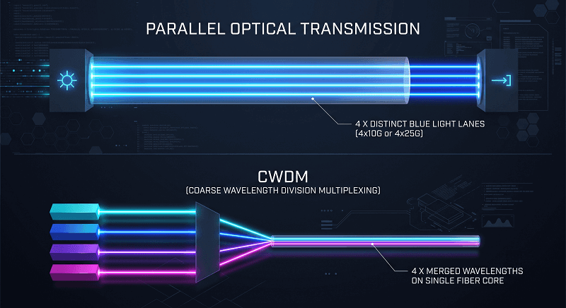
SR4 and its extended cousins use parallel optics over one MPO ribbon. LR4, ER4, and LR4-Lite use four CWDM wavelengths over a single LC duplex pair. PLR4 and PSM4 bridge the two worlds by splitting one 40G MPO port into four 10G single-mode links. For cable and harness details, see our QSFP cables and MPO breakout guide.
The 4×10G Lane Architecture
Inside a QSFP+ transceiver, four electrical lanes operate in parallel. When the host port is configured for 40G operation, the host ASIC treats these lanes as one aggregate 40G interface.
When a supported port is configured for 4×10G breakout mode, the same physical QSFP+ port is divided into four independent 10G logical interfaces. Each electrical lane is mapped to a separate optical or copper connection.
In a QSFP+ SR4 module, each lane drives a separate 850 nm VCSEL transmitter. The four transmit lanes and four receive lanes travel through eight active fibers within an MPO-12 interface. The remaining four fiber positions are normally unused.
In a QSFP+ LR4 module, the four lanes do not travel over separate fibers. Instead, the module converts them into four CWDM wavelengths—1271, 1291, 1311, and 1331 nm—and multiplexes the wavelengths onto one single-mode transmit fiber. A second fiber carries the received wavelengths in the opposite direction.
This distinction explains why an MPO-based SR4 module cannot be connected directly to an LC duplex LR4 fiber plant, or vice versa. Although both modules carry four electrical lanes, their optical transmission architectures, connectors, and cabling requirements are different.
SR4 vs LR4 vs ER4: Which Reach Do You Need?
You should select a QSFP+ transceiver according to the distance between the ports, the installed fiber type, and the connector infrastructure.
QSFP+ SR4 is a common choice for short data center links. It supports up to 100 meters over OM3 multimode fiber and up to 150 meters over OM4 multimode fiber. These distances are sufficient for many intra-rack, inter-rack, and row-level connections.
CSR4 and eSR4 extend the reach of parallel multimode optics. Depending on the product and fiber quality, they typically support up to 300 meters over OM3 and up to 400 meters over OM4.
QSFP+ LR4 is designed for duplex single-mode fiber and supports links of up to 10 kilometers. It is commonly used for campus connections, data center interconnects, telecom aggregation, and longer links within large facilities.
QSFP+ ER4 extends the transmission distance to as much as 40 kilometers over single-mode fiber. However, links beyond approximately 30 kilometers are generally treated as engineered links. The complete optical loss budget—including fiber attenuation, connectors, splices, patch panels, and design margin—must be verified before deployment.
Short ER4 links may also require an optical attenuator if the received power would otherwise exceed the receiver’s maximum input level.
LR4-Lite provides a shorter, typically 2-kilometer, single-mode option for environments where standard LR4 offers more reach than necessary.
For an MPO-based multimode fiber plant, SR4, CSR4, or eSR4 is usually the most practical starting point. For a duplex LC single-mode plant, LR4 is the general-purpose option, while ER4 supports longer engineered links.
Some existing duplex multimode installations may also support vendor-specific 40G BiDi or universal modules. These should be evaluated separately because their optical implementation and interoperability requirements differ from those of SR4.
Connectors: MPO vs LC
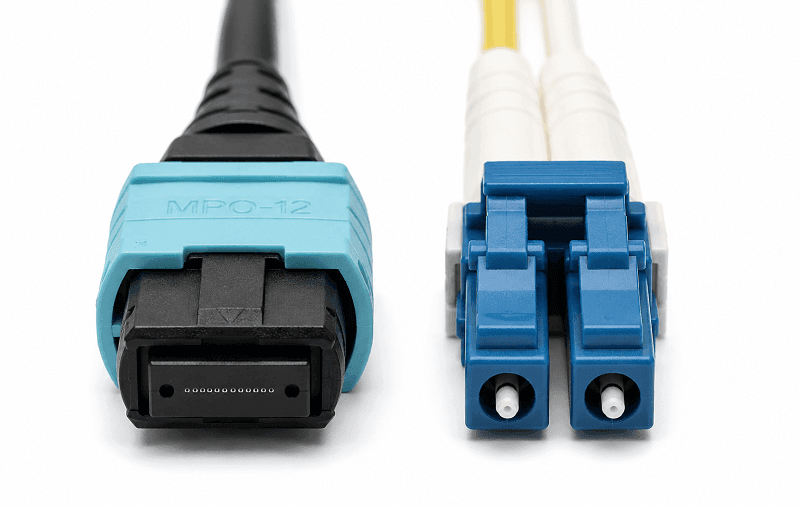
QSFP+ uses two connector families. MPO-12 (or MTP) is the standard for parallel optics like SR4, CSR4, eSR4, PLR4, and PSM4. LC duplex is the standard for CWDM variants like LR4, ER4, and LR4-Lite.
MPO cables are ribbon fibers. Polarity matters. A Method A cable flips the fiber order at one end; Method B flips transmit and receive pairs. Get this wrong and your link won’t come up even though the modules look fine.
LC duplex uses the familiar two-fiber patch cord, one for transmit and one for receive. It’s simpler to deploy, but it requires single-mode fiber for LR4/ER4.
If you are planning a 4×10G breakout connection, the QSFP+ port must use a breakout-capable parallel-optics module, DAC, or AOC. Typical optical options include SR4 over multimode fiber and PLR4 or equivalent 4×10G-LR modules over single-mode fiber.
Power, Heat, and Cost per Gigabit
QSFP+ module power consumption depends on the optical architecture and transmission distance.
Short-reach multimode modules such as SR4 commonly consume approximately 1.5 watts. Single-mode modules such as LR4, ER4, and PLR4 generally consume more power and may require approximately 3.5 watts or more, depending on the product.
For example, if a 48-port switch is populated with modules that consume 3.5 watts each, the optical modules contribute approximately:
48 × 3.5 W = 168 W
This optical load must be included in the switch and rack-level thermal design. Although it may remain manageable compared with the total system power, it is still significant when calculating airflow, cooling capacity, and available power per rack.
Cost per gigabit is one reason 40G continues to compete in brownfield networks. Third-party QSFP+ modules can provide an economical way to retain existing switches and cabling while consolidating multiple 10G links into fewer front-panel ports.
Actual module prices vary widely according to vendor compatibility coding, reach, operating temperature, warranty, order quantity, and market conditions. For this reason, a cost comparison should include:
- The transceivers required at both ends
- The QSFP+ or SFP+ ports consumed
- MPO or LC cabling
- Breakout harnesses or cassettes
- Spare modules
- Compatibility testing
- Power and cooling requirements
A 40G breakout design may reduce the number of transceivers installed on the high-density switch side and free front-panel port capacity. However, it does not eliminate the need for 10G optics or interfaces at the four remote endpoints.
For exact pricing on your switch platform, request a quotation based on the required module type, cable length, temperature range, and compatibility coding.
4×10G Breakout: One QSFP+ Port, Four SFP+ Links
Breakout is one of the best reasons to keep qsfp+ ports in a design. A single 40G QSFP+ port can fan out to four 10G SFP+ links using an MPO-to-4×LC harness or a QSFP+ to SFP+ breakout cable.
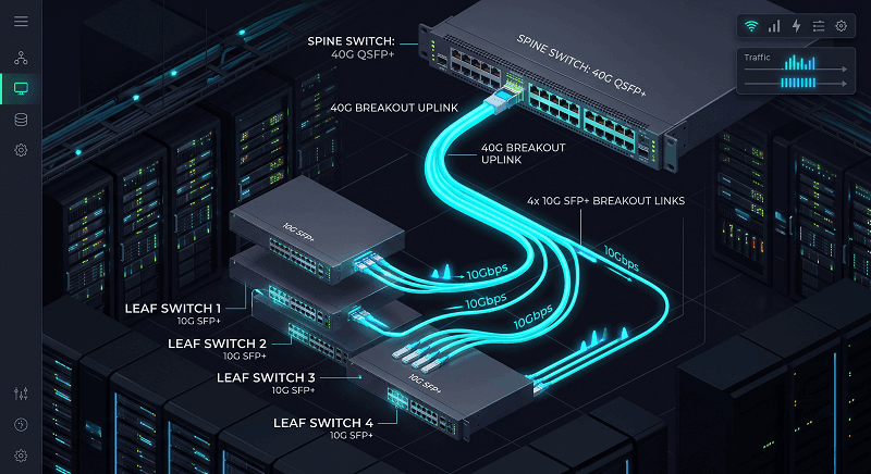
The switch sees one 40G interface, but each lane is wired to a separate SFP+ at the far end. That lets a spine switch feed four access switches without consuming four SFP+ ports on the spine.
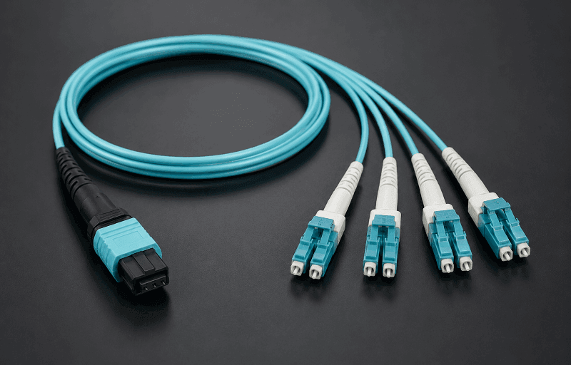
It also saves cable. Instead of four individual duplex fibers, you run one MPO ribbon from the spine to a breakout harness, then four short duplex legs to the access switches. The reduction in cable clutter inside a crowded rack is noticeable.
This is where the QSFP vs SFP comparison gets practical. If the access layer or servers operate at 10G, one breakout-capable QSFP+ port can provide four independent 10G links without consuming four separate high-density switch ports.
A Worked Example: 40G Aggregation in a Leaf-Spine Row
David manages the network for a regional cloud provider in Denver. In March 2026, he needed to connect four leaf switches to a spine switch in the same row. Each leaf switch had one 10G SFP+ uplink, and OM4 multimode fiber was available.
Option A: Four Individual SFP+ SR Links
The conventional design required:
- Four SFP+ SR modules at the spine switch
- Four SFP+ SR modules at the leaf switches
- Four duplex LC multimode fiber connections
- Four SFP+ ports on the spine switch
This design was straightforward, but it consumed four separate spine-side ports and required four spine-side transceivers.
Option B: One QSFP+ SR4 Breakout Connection
The breakout design required:
- One breakout-capable QSFP+ SR4 module at the spine switch
- Four SFP+ SR modules at the leaf switches
- One MPO-to-4×LC OM4 breakout harness
- One QSFP+ port on the spine switch
The spine port was configured in 4×10G breakout mode, creating four independent 10G logical interfaces.
David reduced the number of spine-side optical modules from four to one and freed three front-panel port positions. The four leaf switches continued to receive independent 10G links.
The exact cost difference depended on module and cabling prices, but the design improved port density and reduced switch-side cabling complexity without requiring a 100G migration.
That is the practical value of 40G breakout aggregation. The QSFP+ transceiver provides value through lane density and port consolidation rather than through higher speed at each endpoint.
QSFP+ Transceiver vs QSFP28: Stay, Migrate, or Hybrid?
A qsfp+ transceiver port and a QSFP28 port look identical. That leads to a common qsfp+ vs qsfp28 question: can you mix them?
QSFP28 ports support 40G qsfp+ modules in most switches. The reverse is not true. A QSFP28 100G module will not negotiate down to 40G in a qsfp+ port. The electrical lane rate is 25G per lane on QSFP28, and the older host can’t run it.
Stay on QSFP+ when your upstream is 40G, your endpoints are 10G or 40G, and your fiber matches SR4 or LR4. Migrate to QSFP28 when you need 100G spine uplinks or 25G server ports. Go hybrid by upgrading the spine first and leaving qsfp+ at the leaf until the next refresh. That spreads CapEx and avoids a forklift migration.
For the full speed/generation breakdown, read our QSFP+ vs QSFP28 vs QSFP56 detailed comparison. If you’re already planning the 100G layer, our complete QSFP28 100G guide has the next steps.
Vendor Compatibility and Coding Reality
Marcus bought the same third-party qsfp+ SR4 module for two switches. In the Arista switch it came up immediately. In the Cisco switch it logged an unsupported-transceiver warning and refused to light.
The module wasn’t broken. The switch checks the vendor ID burned into the EEPROM. If the ID doesn’t match the platform’s allow-list, the port can be blocked or limited. Some vendors let you override with a command; others won’t.
Arista and many white-box vendors are more permissive. Cisco often requires compatible coding. Juniper maintains platform-specific matrices. Always check the switch compatibility list before you order.
DDM/DOM helps after installation. Voltage, temperature, Tx/Rx power, and bias current are exposed over the I²C bus. If a link degrades, DDM shows whether the issue is the module, the fiber, or the remote end.
How to Choose a QSFP+ Transceiver
Follow this decision tree when you’re ready to order:
1. Confirm the switch supports qsfp+ and the exact 40GBASE variant you need.
2. Measure the link distance and identify the installed fiber (OM3, OM4, or single-mode).
3. Pick the reach class: SR4 for OM4 up to 150 m, CSR4/eSR4 for 300–400 m, LR4 for 10 km single-mode, ER4 for 40 km.
4. Match the connector to your cable plant: MPO-12 for parallel optics, LC duplex for CWDM.
5. Verify vendor coding or buy MSA-compatible modules with the right EEPROM for your switch.
6. Budget for optics, cables, and spare modules; plan for breakout harnesses if you need 4×10G.
If you’re unsure about the EEPROM or the platform matrix, contact our networking experts before you buy. A five-minute compatibility check beats a week of RMAs.
FAQ
What does QSFP+ stand for?
QSFP+ stands for Quad Small Form-factor Pluggable Plus. It is a four-lane pluggable interface commonly used for nominal 40 Gigabit Ethernet connections.
What is the difference between QSFP+ and QSFP28?
QSFP+ typically uses four approximately 10G electrical lanes to provide a 40G interface. QSFP28 typically uses four approximately 25G electrical lanes to provide a 100G interface.
They use similar physical form factors, but their electrical lane rates and host-interface requirements are different.
Can I use a QSFP+ module in a QSFP28 port?
Often, yes. Many QSFP28 ports support QSFP+ modules at 40G, but compatibility depends on the specific switch, port, line card, software version, and configuration.
Always verify the platform’s hardware compatibility list before deployment.
What is the difference between QSFP+ SR4 and LR4?
QSFP+ SR4 uses four parallel 850 nm optical lanes over multimode fiber and normally has an MPO-12 connector.
QSFP+ LR4 uses four CWDM wavelengths over a duplex single-mode fiber pair and normally has an LC duplex connector.
SR4 is primarily intended for shorter data center links, while LR4 supports distances of up to 10 kilometers.
How far can QSFP+ LR4 reach?
QSFP+ LR4 supports links of up to 10 kilometers over compatible single-mode fiber, subject to the specified optical loss budget.
QSFP+ ER4 extends the nominal reach to as much as 40 kilometers, although longer ER4 connections require careful link-budget engineering.
Can QSFP+ be broken out to 10G?
Yes, but only when the switch port and module support breakout operation.
A breakout-capable QSFP+ SR4 module can connect to four SFP+ SR interfaces using an MPO-to-4×LC multimode harness. A breakout-capable PLR4 or equivalent parallel single-mode module can connect to four SFP+ LR interfaces.
A standard LC-duplex QSFP+ LR4 module cannot be passively broken out into four SFP+ LR links.
Does a switch still see one 40G interface after breakout?
No. After a supported QSFP+ port is configured for 4×10G breakout mode, the switch normally exposes four independent 10G logical interfaces.
The exact interface naming convention depends on the switch operating system.
Is QSFP+ backward compatible with QSFP28?
The more accurate question is whether a QSFP28 port can accept a QSFP+ module.
Many QSFP28 ports can operate with QSFP+ modules at 40G. However, a standard 100G QSFP28 module normally cannot operate in a QSFP+ host port because the host does not support the required electrical lane rate.
Can all QSFP+ SR4 modules support 4×10G breakout?
No. Although many QSFP+ SR4 modules support breakout, some vendor-specific variants do not.
You must confirm both module interoperability with 10GBASE-SR receivers and host-port support for 4×10G channelization.
Conclusion
QSFP+ remains a practical networking option rather than simply obsolete technology. It is well suited to brownfield 40G aggregation, 4×10G breakout connections, and cost-sensitive network layers where 100G is not yet required.
The correct QSFP+ transceiver depends on the transmission distance, fiber type, connector, optical architecture, switch capabilities, and vendor compatibility requirements—not only the headline speed.
Use SR4 and its extended-reach variants for MPO-based multimode data center links. Use LR4 for duplex single-mode campus and data center interconnect applications. Use ER4 for longer engineered single-mode links. Use a breakout-capable SR4, PLR4, DAC, or AOC when one QSFP+ port needs to provide four independent 10G connections.
Move to QSFP28 when the endpoints and surrounding network infrastructure can actually use 100G capacity. Otherwise, retaining a properly designed 40G layer can reduce migration costs while continuing to provide reliable performance.
If you are mapping these options to a real deployment, explore FiberMall’s optical transceiver solutions or contact our networking specialists for a compatibility review. Selecting the correct optic for each network layer can improve reliability, simplify cabling, and reduce unnecessary infrastructure costs.
Related Products:
-
 H3C QSFP-40G-SR4-MM850 Compatible 40G QSFP+ SR4 850nm 150m MTP/MPO MMF DDM Transceiver Module
$25.00
H3C QSFP-40G-SR4-MM850 Compatible 40G QSFP+ SR4 850nm 150m MTP/MPO MMF DDM Transceiver Module
$25.00
-
QSFPP-40G-IR4 40G QSFP+ IR4 1310nm (CWDM4) 2km LC SMF DDM Transceiver Module
$129.00
-
QSFPP-40G-LR4-PSM 40G QSFP+ LR4 PSM 1310nm 10km MTP/MPO SMF DDM Transceiver Module
$149.00
-
QSFPP-40G-UNIV 40G QSFP+ UNIV 1310nm 150m/2km LC MMF/SMF DDM Transceiver Module
$149.00
-
Gigamon QSF-503 Compatible 40G QSFP+ LR4 1310nm (CWDM4) 10km LC SMF DDM Transceiver Module
$149.00
-
QSFPP-40G-BD-RX 40G QSFP+ Bi-Directional 850nm/900nm 100m/150m Duplex LC MMF Optic Module Receiver Only
$165.00
-
Cisco QSFP-40G-LR4-20 Compatible 40G QSFP+ LR4 1310nm CWDM4 20km LC SMF DDM Transceiver Module
$175.00
-
QSFP-40G-SWDM4 40G QSFP+ SWDM4 850nm-940nm 350m LC MMF DDM Optical Transceiver
$249.00
-
QSFPP-40G-SR-BD 40G QSFP+ SR Bi-Directional 850nm/900nm 100m/150m Duplex LC MMF Transceiver Module
$249.00
-
QSFPP-40G-ER4 40G QSFP+ ER4 1310nm (CWDM4) 40km LC SMF DDM Transceiver Module
$449.00
-
QSFPP-40G-ZR4-Lite 40G QSFP+ ZR4 Lite CWDM4 60km LC SMF DDM Optical Transceiver Module
$599.00
-
QSFPP-40G-ZR4 40G QSFP+ ZR4 LWDM4 80km LC SMF DDM Optical Transceiver Module
$1200.00
-
QSFPP-40G-EZR4 40G QSFP+ EZR4 DWDM4 100km LC SMF DDM Optical Transceiver Module
$1600.00
-
QSFPP-DW40G22-80C 40G QSFP+ DWDM C22 100GHz ZR 80km 1559.79nm LC SMF DDM Transceiver Module
$1650.00