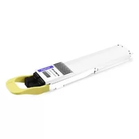

As AI clusters grow from hundreds to thousands of accelerators, traditional electrical and pluggable optical interconnects face increasing challenges in bandwidth density, power consumption, and signal integrity. A 102.4T NPO switch (Near-Packaged Optics switch) addresses these limitations by placing optical engines close to the switching ASIC, shortening high-speed electrical paths and enabling high-density optical connectivity. This article examines a practical 102.4T NPO switch architecture, including its optical configuration, thermal management, internal fiber routing, mechanical assembly, software management, and future development toward 204.8T platforms.
Why Scale-Up Networks Need an NPO Switch
AI infrastructure increasingly relies on large-scale GPU and accelerator clusters that require extremely high bandwidth and low-latency communication. Within these clusters, the scale-up network connects processors and accelerators that must exchange large volumes of data with minimal communication overhead.
Traditional copper and pluggable optical architectures face different limitations as network bandwidth increases. Near-Package Optics provides an alternative by moving optical engines closer to the switching ASIC while retaining a degree of modularity and serviceability.
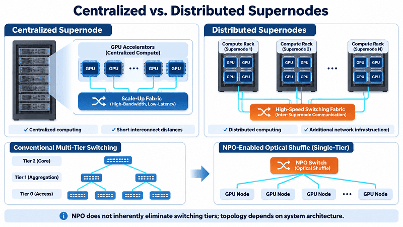
Centralized vs. Distributed Supernodes
Scale-up networks generally adopt two deployment approaches: centralized and distributed supernodes.
A centralized supernode integrates a large number of GPUs within a single physical system or rack. For example, NVIDIA NVL72 connects 72 GPUs through a high-bandwidth NVLink fabric. This architecture provides direct, high-speed communication but places considerable demands on power delivery, cooling, rack structure, and physical interconnection.
As the number of accelerators increases, copper interconnect distance and cable-management complexity become important constraints.
A distributed supernode spreads GPUs across multiple compute racks and connects them through a switching fabric. This approach improves deployment flexibility and reduces the physical concentration of computing resources. However, conventional two-tier switching architectures introduce additional switching stages, equipment costs, and network-management complexity.
An NPO-based switching architecture offers another approach. By combining high-capacity optical engines with shuffle-based connectivity, a single-tier network can support larger distributed scale-up domains without relying on the same two-stage switching structure.
The objective is to extend scale-up connectivity while reducing interconnection power, communication latency, and infrastructure complexity.
What NPO Changes: DSP Removal and Single-Tier Shuffle
In conventional pluggable optical modules, high-speed electrical signals travel from the switching ASIC across PCB traces and through the module’s electrical interface before reaching the optical conversion circuitry.
At increasingly high lane rates, this electrical channel introduces insertion loss and signal-integrity challenges. A DSP is commonly used to compensate for channel impairments, but it also consumes additional power and introduces processing latency.
NPO changes this arrangement by placing optical engines near the switching ASIC.
The shorter electrical connection makes it possible to use a linear direct-drive architecture, removing the need for a conventional retiming DSP in the optical engine’s signal path.
This approach provides two important benefits:
- Lower power consumption: Removing the DSP reduces the power required for electrical signal processing.
- Lower latency: A shorter signal path and reduced processing can decrease end-to-end communication delay.
NPO can also work with optical shuffle architectures. Instead of relying on multiple switching tiers, optical connections can be arranged to support direct communication between different compute groups within a larger supernode.
The result is a network architecture designed to improve bandwidth efficiency while reducing the cost and latency associated with additional switching stages.
The Measurable Gains
A published 102.4T NPO reference design reports several improvements compared with a traditional pluggable optical switching architecture.
| Performance metric | Reported result | Engineering significance |
| System power | Approximately 1,000 W lower | Reduced power associated with DSP removal |
| End-to-end latency | Nearly 100 ns lower | Less signal-processing and interconnect overhead |
| Signal architecture | Linear direct drive | Shorter electrical channel |
| BER | Better than 1 × 10⁻¹⁰ across all ports in the reported test | Demonstrates signal integrity in the reference implementation |
| Bandwidth roadmap | 204.8T, with potential for 409.6T | Supports future system scaling |
These figures describe a specific reference design and its reported comparison, rather than guaranteed improvements for every NPO implementation. Actual results depend on ASIC characteristics, optical-engine design, link configuration, and measurement conditions.
102.4T NPO Switch Architecture at a Glance
A 102.4T NPO switch integrates high-speed switching and optical conversion into a compact system architecture. Instead of placing optical transceivers along the front panel, it distributes optical engines around the central switching ASIC.
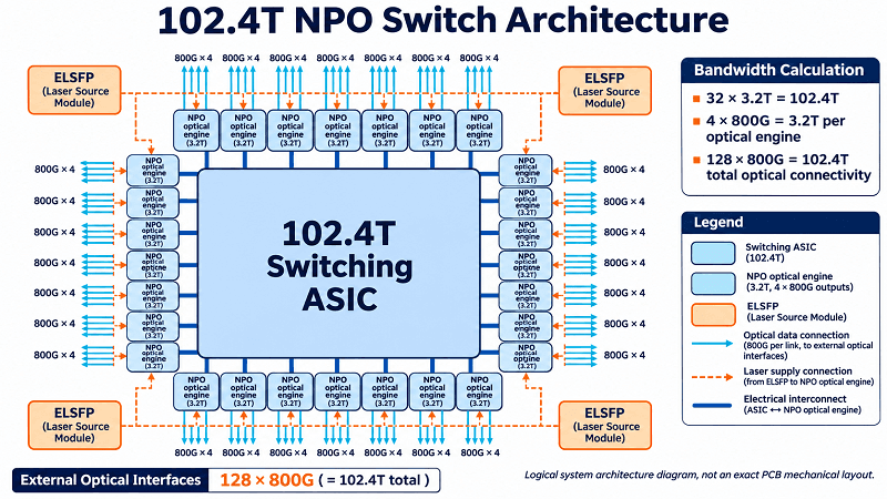
One practical implementation uses 32 optical engines, each providing 3.2T of aggregate bandwidth.
This architecture creates 128 external 800G optical connections, providing a total switching bandwidth of 102.4 Tbps.
System Specifications
The following specifications describe the reference 102.4T NPO switch architecture.
| Parameter | Reference configuration |
| Switching capacity | 102.4 Tbps |
| Switch ASIC | 1 × 102.4T ASIC |
| Optical engines | 32 × 3.2T NPO |
| External light sources | 32 × ELSFP |
| External optical interfaces | 128 × 800G |
| Optical connector | MPO-16 |
| Electrical signaling | 100G-class lanes (112G PAM4 signaling) |
| Optical engine placement | Symmetrically around the ASIC |
| Chassis height | 4RU |
| Management | Front-accessible, field-replaceable management card |
Each 3.2T NPO engine handles 32 electrical channels and provides four 800G optical outputs. Across 32 engines, the system delivers 128 optical interfaces.
The external laser source is implemented separately through ELSFP modules, allowing the light source to be replaced without replacing the entire optical engine.
Bandwidth calculation:
- 32 × 3.2T NPO engines = 102.4T
- 4 × 800G optical outputs per engine = 3.2T
- 32 × 4 = 128 optical outputs
- 128 × 800G = 102.4T
This configuration illustrates how optical-engine aggregation translates into high-density external connectivity.
Four Design Shifts That Break Legacy Assumptions
An NPO switch is not simply a conventional switch with its optical modules moved inside. It changes several fundamental aspects of hardware design.
1. Optical engines move from the front panel to the ASIC area.
The optical engines are positioned around the switching chip to minimize high-speed electrical trace length. This requires much tighter PCB layout coordination.
2. Optical fibers move inside the chassis.
Traditional switches route optical connections directly from front-panel transceivers to external fiber cables. NPO systems must manage hundreds or potentially thousands of internal fiber positions between optical engines and front-panel adapters.
3. Optical-engine installation becomes a mechanical assembly process.
Instead of conventional front-panel insertion, socket-based NPO engines require controlled mechanical compression to maintain reliable electrical contact.
4. Software management shifts from individual modules to shared physical devices.
Multiple logical ports can share one optical engine and its management resources. Software must therefore distinguish between logical port operations and physical device management.
These changes make NPO a complete system-engineering challenge involving electronics, optics, mechanics, thermal design, and software.
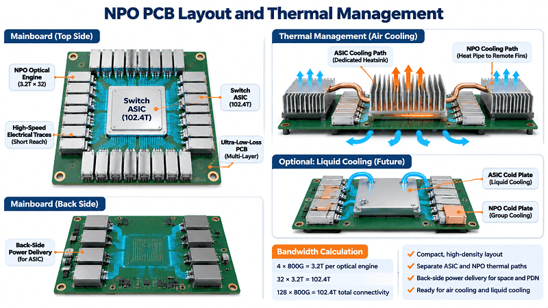
Layout and Thermal Design: The Cost of Moving Optics Next to the ASIC
Moving optical engines closer to the switching ASIC reduces electrical channel length, but it also concentrates components within a limited PCB area.
In a 102.4T NPO switch, 32 optical engines must fit around one high-capacity switching chip. Each engine requires high-speed electrical connections, optical fiber access, mechanical support, and sufficient thermal clearance.
The result is a much more demanding layout than a traditional front-panel optical architecture.
PCB Real Estate and Ultra-Low-Loss Material
In a conventional switch, optical modules occupy the front-panel area, leaving the main PCB layout relatively concentrated around the ASIC, memory, power circuits, and other supporting components.
With NPO, optical engines occupy the space immediately surrounding the ASIC.
This creates several challenges:
- Limited PCB routing space around the switching chip.
- High-density SerDes connections between the ASIC and optical engines.
- Increased sensitivity to insertion loss and signal reflection.
- More complicated component placement and manufacturing constraints.
Ultra-low-loss PCB materials are therefore essential for maintaining signal integrity.
In the reference design, the mainboard uses Ultra-Low-Loss material, with combined host and package insertion loss specified at no more than approximately 13 dB at 26.56 GHz.
This electrical-channel performance helps support linear direct-drive operation.
PCB design must also account for trace length matching, impedance control, via transitions, connector characteristics, and the electrical behavior of the optical-engine socket.
Power Delivery on the Back Side of the Board
Power delivery becomes another major challenge when optical engines occupy most of the available space around the ASIC.
The switching chip requires substantial power, while the NPO engines and their supporting circuits introduce additional power-delivery requirements.
Placing conventional power modules near the optical engines could interfere with high-speed routing and mechanical installation.
One solution is to move dedicated ASIC power-delivery modules to the back side of the PCB.
This arrangement provides several advantages:
- Frees valuable component-placement space around the ASIC.
- Shortens the power-delivery path to the switching chip.
- Helps reduce power distribution network (PDN) impedance.
- Improves transient response under changing ASIC workloads.
The key is to coordinate power distribution, signal routing, PCB mechanical strength, and component cooling rather than optimizing each subsystem independently.
Decoupling NPO and ASIC Thermal Paths
Thermal management is one of the most demanding aspects of NPO switch design.
The switching ASIC and optical engines operate in close proximity, creating concentrated heat sources. However, optical engines can have different temperature sensitivities and cooling requirements from the main switching chip.
If both components share an unsuitable thermal path, heat from the ASIC can increase the optical-engine inlet temperature and affect optical performance.
A practical cooling architecture should therefore separate their thermal management paths.
In an air-cooled design, heat pipes can move the NPO heatsink fins away from the ASIC’s main airflow path. This reduces the likelihood that the optical engines receive preheated air from the switching chip.
The system can also reserve space for future liquid cooling.
A liquid-cooled implementation may divide the 32 NPO engines into four independent cold-plate groups. Floating copper pipes connect the cold plates while accommodating mechanical assembly tolerances and reducing stress.
Additional design considerations include:
- Compliant thermal interface materials to compensate for component-height differences.
- Controlled contact pressure between optical engines and cooling assemblies.
- Independent airflow and heatsink optimization.
- High-density fin structures for the switching ASIC.
- Mechanical accommodation for future higher-power ASIC generations.
The goal is not simply to remove heat, but to maintain stable and predictable operating temperatures across the entire optical and electrical system.
In-Chassis Fiber Routing: Giving 1,000+ Fibers a Lane
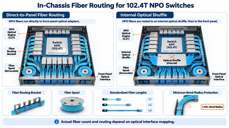
Unlike traditional pluggable switches, an NPO switch contains a large number of internal optical connections.
In the 102.4T reference architecture, 32 optical engines provide 128 MPO-16 external interfaces. If all 16 fiber positions of every interface are populated, the connector configuration represents up to 2,048 fiber positions.
The actual number of active fibers depends on the optical interface and fiber utilization.
This scale makes internal fiber management a critical part of the mechanical design.
Poor fiber routing can lead to excessive bending, connector stress, assembly difficulties, and longer maintenance times.
Brackets, Spools and Fiber-Length Standardization
A structured fiber-routing system helps control the optical paths between the NPO engines and front-panel adapters.
A practical design uses two main mechanical components.
Fiber-routing brackets
Brackets are installed around the NPO output areas to guide fiber bundles along predefined paths. Interlocking or comb-shaped structures help maintain consistent spacing, prevent fiber crossover, and control bend radius.
Fiber-management spools
Excess fiber length can be stored on removable spools positioned between the mainboard and front panel.
Instead of manufacturing many different fiber lengths, the design can standardize the internal fiber assemblies into three or fewer length specifications.
This reduces inventory complexity and improves assembly consistency.
The routing structure should also allow technicians to access individual fiber bundles without disturbing unrelated connections.
Direct-to-Panel vs. Internal Shuffle
Two main fiber-routing approaches can be used.
| Design approach | Description | Main advantage |
| Direct-to-panel | NPO fibers run directly to front-panel optical adapters | Simpler routing and fewer internal optical connections |
| Internal shuffle | Fibers pass through an internal optical distribution or shuffle structure before reaching the panel | Supports more complex multi-chip connectivity |
For a single-ASIC switch without internal optical cross-connections, direct-to-panel routing is generally simpler.
It also avoids additional optical connectors that could introduce insertion loss and return loss.
For multi-ASIC systems requiring optical channel interconnection, an internal shuffle structure may be more appropriate. It can simplify external cabling and improve overall network installation and maintenance.
The right choice depends on the switching topology, optical channel mapping, chassis layout, and serviceability requirements.
Compression Hardware: A Split Cover Beats Tolerance Stack-Up
Mechanical reliability is particularly important in socket-based NPO architectures.
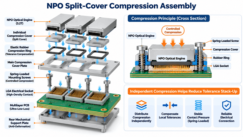
The optical engine connects to the mainboard through an LGA socket. Reliable electrical contact requires continuous and evenly distributed compression across the module.
However, a 102.4T switch may have eight optical engines arranged side by side in each direction around the ASIC. PCB routing and component placement can limit the available spacing and screw positions.
Using one large cover plate for all eight engines creates a potential tolerance problem.
Small variations in socket height, optical-engine dimensions, PCB flatness, and assembly position can accumulate along the mechanical stack. As a result, some modules may receive insufficient contact pressure while others experience excessive pressure.
A split-cover design provides a more controlled solution.
The structure consists of three main elements:
Individual small covers: Each optical engine receives a dedicated small cover attached to a larger supporting plate. An elastic rubber ring helps absorb local assembly tolerances and distribute compression more evenly.
Main cover plate: The larger plate is secured to the PCB using spring-loaded screws. The springs provide controlled and sustained compression while the plate maintains structural stability. The reference design specifies a flatness target within 0.1 mm.
Backplate support structure: A mechanical support structure on the back side of the PCB locks into the main cover assembly, helping prevent PCB deformation under compression. Local openings accommodate components mounted on the rear side.
Together, these components create a more reliable compression structure.
The important principle is to control mechanical tolerances at the individual module level rather than allowing multiple tolerance variations to accumulate across one large assembly.
Software and Operations: Making NPO Behave Like a Pluggable
Hardware integration is only part of the NPO design challenge. The management software must also support a different relationship between logical optical ports and physical optical engines.
Traditional pluggable modules generally expose an individual management interface for each module. NPO systems can have multiple logical ports sharing one physical optical engine and its management resources.
The software architecture must account for this difference while maintaining compatibility with existing optical management applications.
CMIS Three-Dimensional Addressing
NPO and ELSFP management can use a CMIS-based register structure organized through three addressing dimensions:
- Bank: Selects a register bank.
- Page: Selects a register page within the bank.
- Byte: Identifies a specific register offset.
This Bank:Page structure requires additional management operations compared with a conventional flat register-access model.
The challenge becomes more significant when several logical ports share one physical NPO engine.
A suitable software architecture should provide two management levels.
Logical port-level management
Each logical port retains a familiar management interface for independent status monitoring, control, and fault reporting.
Physical device-level management
A separate device-level interface provides access to the complete register space for firmware upgrades, configuration validation, diagnostics, and fault-data collection.
The underlying driver translates logical port offsets into the corresponding Bank ID, Page ID, and byte offset.
It also manages bank and page switching, concurrent access, and register-operation locking.
This abstraction allows higher-level applications to continue using familiar optical management workflows without requiring extensive application-level modifications.
Power-Up and Initialization Sequencing
External laser sources introduce additional coordination requirements between the NPO engines and ELSFP modules.
The switching ASIC, NPO engines, and external laser sources must be initialized in a controlled sequence to prevent abnormal optical output or link-state errors.
A reference implementation uses the following power-up sequence:
- MAC initialization: Power up and initialize the switching ASIC and MAC-related functions.
- NPO initialization: Initialize the optical engines and their management interfaces.
- ELSFP initialization: Power up the external laser sources.
- Optical verification: Enable low-level or half-power optical output and verify light injection into the optical engines.
- Normal operation: Enable full optical output after successful verification.
Software-controlled restart procedures should also disable optical output before resetting the relevant devices.
This sequence helps prevent unexpected optical states and improves system-level startup reliability.
What Comes Next: 6.4T NPO and 204.8T Platforms
The evolution of NPO will depend on improvements in optical-engine bandwidth, mechanical integration, optical connectivity, and thermal management.
A 102.4T platform provides a foundation for higher-capacity systems, but future generations will need to address additional challenges in density, serviceability, and power efficiency.
Pluggable FAU
In some current NPO implementations, the optical engine and its fiber pigtail are integrated into one assembly.
If the optical engine or fiber termination fails, replacing the assembly may require both module removal and fiber rerouting.
A pluggable Fiber Array Unit (FAU) could separate these maintenance operations.
Technicians could replace the optical engine independently of the internal fiber assembly, potentially reducing maintenance time and improving serviceability.
This approach would require reliable optical alignment, connector repeatability, low insertion loss, and robust mechanical interfaces.
ELSFP vs. Integrated Laser
ELSFP separates the external laser source from the optical engine.
Its main advantage is serviceability: a failed laser can be replaced without replacing the entire NPO engine.
However, external laser architecture introduces additional considerations:
- Dedicated ELSFP board and front-panel space.
- Polarization-maintaining fiber requirements in applicable designs.
- Additional optical connections and alignment requirements.
- Connector cleanliness and contamination risks.
An integrated laser architecture places the light source within the optical engine.
This can reduce external laser-routing complexity and save chassis space, but it also changes the maintenance model. A laser failure may require replacement of the entire optical engine.
The choice between ELSFP and integrated lasers depends on laser reliability, system architecture, repair strategy, and total cost of ownership.
2.5D / 3D Packaging
Packaging technology will be another important factor in future NPO development.
A conventional 2D optical-engine layout can occupy considerable PCB area, limiting how closely optical engines can be positioned around the ASIC.
Advanced 2.5D and 3D packaging technologies can improve component integration and reduce the physical footprint of optical engines.
Potential benefits include:
- Higher interconnect density.
- Shorter electrical connections.
- Reduced PCB routing complexity.
- Improved optical-engine placement flexibility.
- Greater potential for higher-bandwidth system designs.
The next development stage includes 6.4T NPO engines and 204.8T switching platforms. These designs will need coordinated improvements across the ASIC, optical engine, packaging, laser architecture, and cooling system.
The long-term objective is to extend high-density optical connectivity from 512-accelerator supernodes toward systems containing thousands of accelerators.
FAQ
What is the difference between NPO and CPO?
NPO places optical engines near the switching ASIC but keeps them as separate modules or assemblies, generally with a socket-based or modular interface.
CPO integrates optical engines directly into the same package as the switching ASIC.
Both approaches shorten electrical connections and can reduce power consumption. However, NPO generally offers greater module-level serviceability, while CPO provides a more tightly integrated packaging architecture.
Why remove the DSP from the optical module?
A DSP compensates for electrical-channel impairments in conventional retimed optical modules. However, it consumes additional power and introduces processing latency.
NPO shortens the electrical connection between the ASIC and optical engine, making linear direct-drive operation possible in suitable designs.
Removing the conventional retiming DSP reduces power consumption and signal-processing overhead.
How many 800G ports does a 102.4T NPO switch provide?
In the reference architecture discussed in this article, a 102.4T NPO switch provides 128 × 800G optical ports.
The system uses 32 × 3.2T optical engines, with each engine providing four 800G MPO-16 optical interfaces.
The total bandwidth is:
32 × 3.2T = 128 × 800G = 102.4T.
Can existing optical module software manage an NPO switch?
Yes, with an appropriate software abstraction layer.
NPO management may use CMIS-based Bank:Page addressing, and multiple logical ports may share one physical optical engine.
The underlying driver must translate logical port operations into the correct physical register accesses and manage concurrent operations.
With separate logical port-level and device-level management interfaces, existing optical management applications can retain familiar workflows with limited or no application-level changes.
Conclusion
The 102.4T NPO switch represents an important evolution in optical interconnect architecture for large-scale AI networks. By moving optical engines closer to the switching ASIC, it reduces electrical channel length, enables DSP-free linear drive, and supports high-density optical connectivity for scale-up networks.
However, successful NPO deployment requires more than optical-engine integration. PCB layout, power delivery, thermal separation, internal fiber routing, mechanical compression, and software management must all be designed as one coordinated system.
As 6.4T optical engines and 204.8T switching platforms develop, improvements in FAU serviceability, laser architecture, and 2.5D/3D packaging will play an important role in making NPO more scalable and maintainable.
For AI infrastructure developers, NPO offers a practical path toward higher-bandwidth, lower-power optical connectivity while preserving modularity and system-level flexibility.
Related Products:
-
 NVIDIA MMA4Z00-NS Compatible 800GBASE 2 x SR4/SR8 OSFP PAM4 850nm 100m DOM Dual MPO-12 MMF Optical Transceiver Module
$550.00
-
NVIDIA MMA4Z00-NS-FLT Compatible 800GBASE 2 x SR4/SR8 OSFP RHS/Flat Top PAM4 850nm 100m DOM Dual MPO-12 MMF Optical Transceiver Module
$600.00
-
NVIDIA MMS4X00-NM Compatible 800GBASE 2 x DR4/DR8 OSFP IHS/Closed Finned Top PAM4 1310nm 500m DOM Dual MTP/MPO-12 SMF Optical Transceiver Module
$600.00
-
NVIDIA MMS4X00-NM-FLT Compatible 800GBASE 2 x DR4/DR8 OSFP Flat Top PAM4 1310nm 500m DOM Dual MTP/MPO-12 SMF Optical Transceiver Module
$650.00
-
NVIDIA MMS4X50-NM Compatible 800G 2x FR4 OSFP IHS/Closed Finned Top PAM4 1310nm 2km DOM Dual Duplex LC SMF InfiniBand NDR Optical Transceiver Module
$1000.00
-
NVIDIA MMS4A00 (980-9IAH1-00XM00) Compatible 1.6T 2 x DR4/DR8 OSFP224 PAM4 1311nm 500m IHS/Finned Top Dual MPO-12 SMF Optical Transceiver Module
$1500.00
-
NVIDIA MMS4A50 Compatible 1.6T 2xFR4/FR8 OSFP224 PAM4 1310nm 2km IHS/Finned Top Dual Duplex LC SMF Optical Transceiver Module
$1800.00
-
NVIDIA MMS4A00-RHS Compatible 1.6T 2xDR4/DR8 OSFP224 PAM4 1311nm 500m RHS/Flat Top Dual MPO-12/APC InfiniBand XDR SMF Optical Transceiver Module
$2000.00