
A CWDM network design starts with three practical questions: how many fiber strands are available, how much optical loss the transmission path introduces, and how many independent channels the network needs.
These three factors determine whether CWDM is a practical solution and which MUX/DEMUX configuration can support the required services.
Many guides start with the wavelength grid. That is not where the design begins. The CWDM wavelength grid is defined by ITU-T G.694.2, with nominal channel spacing of 20 nm. You select the wavelengths that fit your application, but you cannot freely change the grid.
What you can control is how efficiently you use the existing fiber infrastructure, how much insertion loss your optical components introduce, and how much hardware you need to purchase.
There is also an important cost consideration. CWDM does not automatically reduce the cost of optical transceivers. Wavelength-specific CWDM modules generally carry a price premium over standard gray optics. What CWDM can save is fiber capacity.
The real design question is whether the cost of the additional CWDM hardware is lower than the cost of obtaining or leasing the fiber strands that the system saves.
This guide follows a practical engineering sequence:
- Assess the existing fiber infrastructure.
- Select the network topology.
- Develop the CWDM channel plan.
- Verify transceiver wavelength and reach availability.
- Calculate the complete CWDM link budget.
- Build and compare the bill of materials.
- Commission and test the network.
Product prices in this article are indicative FiberMall list prices checked on November 16, 2026. They are subject to change and should be reconfirmed before ordering.
Key Takeaways
- Start with available fiber strands and measured span loss before selecting CWDM hardware.
- A dual-fiber CWDM system typically uses one fiber pair to carry multiple independent wavelength channels in both directions.
- MUX/DEMUX insertion loss increases with channel count. An 8-channel configuration typically introduces up to 2.4 dB per end, while an 18-channel configuration can introduce up to 5.4 dB per end.
- A transceiver’s rated transmission distance does not guarantee the same reach after MUX/DEMUX insertion loss is included.
- FiberMall’s 10G CWDM transceiver availability varies by wavelength and reach. Check the exact SKU before finalizing the channel plan.
- Reserving spare MUX ports does not inherently increase the insertion loss of existing channels.
- A passive CWDM ring does not provide automatic protection switching. Network-level protection requires an appropriate switching or routing mechanism.
Start With the Fiber Infrastructure You Have
Before selecting optical transceivers or opening a MUX/DEMUX catalog, document the existing fiber infrastructure.
Five pieces of information are essential.
1. Available fiber strands
Count the usable strands between each pair of sites. Include:
- Active fiber strands.
- Dark or unused fiber strands.
- Fiber pairs already allocated to existing services.
- Fiber reserved for future expansion.
- Any strands that cannot be used because of physical damage or excessive loss.
Count strands by route segment rather than simply counting the total number of fibers across the entire network.
2. Fiber type
Identify the installed fiber standard.
For example, G.652.D single-mode fiber has low water-peak attenuation around 1383 nm, while older G.652.A fiber may exhibit higher attenuation in this region.
This distinction matters when considering CWDM channels around 1371 nm and 1391 nm.
If the fiber type is unknown, do not assume that every wavelength in the CWDM grid will perform equally well.
3. Measured span loss
Measure the actual end-to-end optical loss whenever possible.
Use an optical loss test set (OLTS), consisting of a calibrated light source and power meter, to measure insertion loss. An OTDR can help identify splice events, connector problems, and other loss locations.
Measurements should be performed at relevant wavelengths rather than relying on a single generic attenuation figure.
4. Splices and connectors
Record the number of fusion splices, connector pairs, patch panels, and intermediate distribution points.
For preliminary planning, engineers often use approximately 0.1 dB per fusion splice and 0.5 dB per connector pair as estimation values. Actual loss must be confirmed by measurement.
5. Existing optical services
Identify all services already operating on the route.
Pay particular attention to:
- Existing 1310 nm Ethernet links.
- PON infrastructure and splitters.
- Existing 1550 nm transmission systems.
- Any WDM equipment already installed.
An existing 1310 nm service cannot automatically pass through a standard 1470–1610 nm CWDM MUX.
If the existing service must share the same fiber pair, select a MUX/DEMUX configuration with a compatible 1310 nm pass-through window. Confirm its passband and insertion-loss specifications before ordering.
A 1310 nm pass-through port is not the same as a standard 1311 nm CWDM channel.
The Three Numbers That Determine the Initial Design
After collecting the infrastructure information, summarize the design requirements into three numbers:
- Available fiber strands on each route segment.
- Measured end-to-end optical loss, including connectors and splices.
- Required wavelength channels by service, direction, and data rate.
Add spare channel capacity to the third number, but distinguish between reserving unused MUX ports and purchasing spare transceivers.
A reserved port does not require an optical module until the channel is activated.
The economic value of CWDM also becomes clearer at this stage.
Compare the total cost of CWDM equipment against the cost of the alternative: installing additional fiber, leasing dark fiber, or using another available transmission route.
That comparison, rather than the transceiver datasheet alone, determines whether a CWDM network design makes financial sense.
Choose the Network Topology Before the Channel Plan
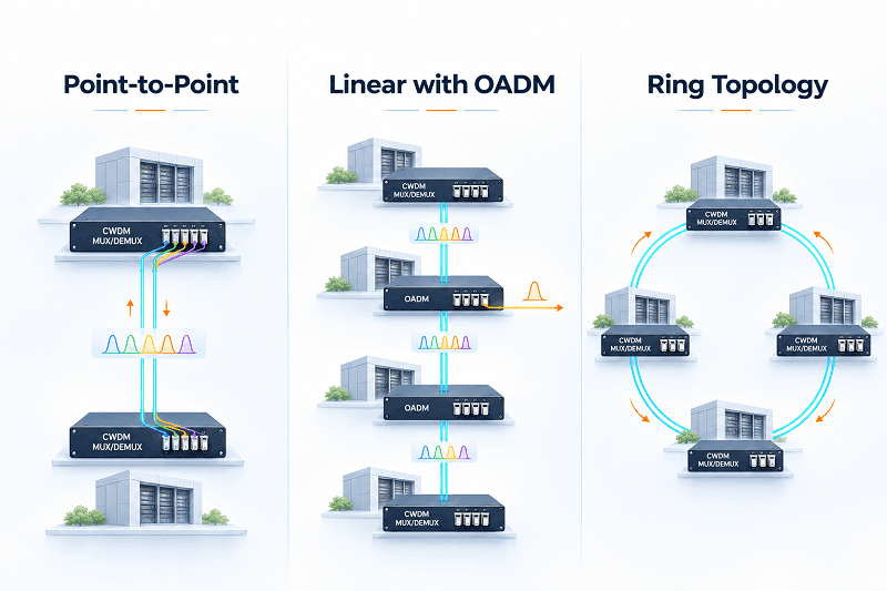
Three topologies cover most CWDM deployments: point-to-point, linear with OADM, and ring.
The physical site layout and service requirements usually determine which one is appropriate.
Point-to-Point
A point-to-point CWDM system uses MUX/DEMUX equipment at two endpoints.
Multiple wavelength channels are combined onto one fiber pair and separated at the receiving end.
This is generally the simplest and most cost-effective configuration when all services connect between the same two locations.
Linear Topology With OADM
A linear CWDM network uses Optical Add-Drop Multiplexers (OADMs) at intermediate sites.
Each OADM can add or drop designated wavelengths while allowing other wavelengths to pass through the node.
This topology is useful when multiple buildings, remote offices, or access sites are connected along one fiber route.
However, every intermediate OADM introduces additional optical loss. The actual express-path and add/drop losses must be taken from the selected device’s specifications.
The channel plan must also identify which wavelengths are dropped, added, and passed through at every site.
For more information, see the CWDM OADM Guide.
Ring Topology
A CWDM ring connects multiple sites in a closed physical path, allowing traffic to reach a destination through either direction.
A ring can provide an alternative physical route, but a passive CWDM ring does not automatically switch traffic when a fiber is cut.
It has no inherent protection-switching controller, monitoring logic, or automatic failover mechanism.
If a span fails, the affected wavelengths remain unavailable unless another network element or protection mechanism redirects traffic.
A passive ring should therefore not be described as a sub-50 ms protection solution.
If the service-level agreement requires fast recovery, the protection mechanism must be designed at the appropriate Ethernet, transport, or routing layer.
Topology Comparison
| Topology | Additional Hardware | Optical Loss Consideration | Protection |
| Point-to-point | Two endpoint MUX/DEMUX units | Endpoint MUX/DEMUX loss | None by itself |
| Linear with OADM | OADM at each add/drop site | Cumulative express and add/drop loss | None by itself |
| Ring | OADM and endpoint equipment as required | Both possible paths must be evaluated | Requires separate protection switching |
Design a Ring for Its Worst Optical Path
For a ring network, calculate the optical loss of both possible routes between communicating nodes.
Do not simply average the two path losses or assume that the longer path is always half the ring circumference.
The backup route can be substantially longer than the primary route, depending on the location of the communicating nodes.
For every wavelength, document:
- Primary path distance.
- Alternate path distance.
- MUX/DEMUX insertion loss.
- OADM express-path loss.
- Connector and splice loss.
- Required engineering margin.
The design must close on the worst path that the service may use.
Build the CWDM Channel Plan
Once the topology is established, assign wavelengths according to service requirements and optical constraints.
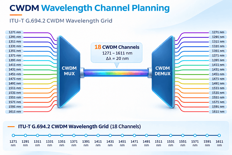
The ITU-T G.694.2 CWDM grid defines 18 nominal center wavelengths with 20 nm spacing:
1271, 1291, 1311, 1331, 1351, 1371, 1391, 1411, 1431, 1451, 1471, 1491, 1511, 1531, 1551, 1571, 1591, and 1611 nm.
Commercial product descriptions commonly use rounded labels such as 1270 nm, 1290 nm, and 1470 nm.
See the complete CWDM Wavelength Chart.
Three factors should guide wavelength assignment.
Consider the Fiber Water Peak
The wavelengths around 1371 nm and 1391 nm are close to the traditional 1383 nm water-peak region.
Older fiber with higher hydroxyl absorption may introduce additional attenuation around this region.
Modern low-water-peak fiber, such as G.652.D, is designed to address this issue.
If the installed fiber type cannot be verified, avoid assigning critical long-distance services to these channels until their actual attenuation has been measured.
Consider Future DWDM Coexistence
Some CWDM wavelengths overlap spectrally with the DWDM C-band operating region.
However, leaving individual CWDM channels unused does not automatically make a network compatible with a future DWDM overlay.
DWDM coexistence requires an appropriate filter architecture, compatible passbands, and a complete optical budget.
If a DWDM upgrade is part of the roadmap, select a compatible upgrade or coexistence architecture before purchasing the CWDM MUX/DEMUX equipment.
See DWDM vs. CWDM for a comparison of the two technologies.
Match Wavelengths to Fiber Attenuation and Transceiver Specifications
Single-mode fiber generally has lower attenuation around the 1550 nm region than around 1310 nm.
However, attenuation is wavelength-dependent, and longer wavelengths do not automatically provide better performance across the entire CWDM grid.
Consider the actual fiber attenuation curve, transceiver specifications, and measured span loss when assigning channels.
Do not assign the longest wavelengths to the longest routes without checking their optical budgets.
Label Every Port by Wavelength
Label MUX/DEMUX ports and patch-panel connections with their actual wavelength.
For example, use:
- 1470 nm
- 1490 nm
- 1510 nm
- 1530 nm
Avoid relying exclusively on channel numbers such as CH1 or CH6.
A technician troubleshooting a network should be able to identify the correct wavelength without needing to find the original MUX datasheet.
Check 10G CWDM Transceiver Availability by Reach
One frequently overlooked issue is that not every CWDM wavelength is available at every transmission distance in a particular product range.
The following table summarizes the 10G CWDM wavelength availability in the FiberMall product range used for this design.
| Rated Reach | Available Wavelength Range | Number of Channels |
| 10 km | 1270–1570 nm | 16 |
| 20 km | 1270–1450 nm | 10 |
| 40 km | 1270–1390 nm and 1470–1610 nm | 15 |
| 60 km | 1270–1330 nm | 4 |
| 80 km | 1470–1610 nm | 8 |
| 100 km | 1470–1550 nm | 5 |
These figures describe the listed product configurations, not universal technical limits of CWDM.
The actual wavelength availability must be confirmed against the selected product SKU and compatibility requirements.
For example, an 8-channel 10G design using 80 km-rated CWDM transceivers must use the available 1470–1610 nm wavelength band.
However, selecting eight available wavelengths does not automatically mean the complete 80 km link will work. The MUX/DEMUX insertion loss must still be included in the optical budget.
The 1.25G CWDM product range offers a broader wavelength selection. FiberMall lists 40 km 1.25G CWDM SFP variants across the 18-channel wavelength grid.
Check the exact product availability and optical specifications at other reach levels before finalizing a channel plan.
The CWDM SFP Selection Guide provides additional information about transceiver selection and wavelength matching.
A Practical CWDM Channel Plan Example
Consider a point-to-point connection between two hub locations, Site A and Site B.
The fiber route is approximately 9 km long, and the network requires six active services with two additional channels reserved for future expansion.
The selected configuration is an 8-channel dual-fiber CWDM MUX/DEMUX operating across 1470–1610 nm.
A possible channel plan is:
| Wavelength | Service | Data Rate | Status |
| 1471 nm | Core uplink | 10G | Active |
| 1491 nm | Distribution link | 10G | Active |
| 1511 nm | Distribution link | 10G | Active |
| 1531 nm | CCTV backhaul | 10G | Active |
| 1551 nm | Administration network | 1.25G | Active |
| 1571 nm | Management network | 1.25G | Active |
| 1591 nm | Future expansion | 10G | Reserved |
| 1611 nm | Future expansion | 10G | Reserved |
All six active services connect between the same two endpoint locations.
If intermediate sites need to add or drop individual services, the design must include the appropriate OADM equipment rather than treating the entire route as a simple point-to-point link.
The two spare wavelengths are assigned in advance so that future transceiver selection and MUX port mapping remain predictable.
A reserved wavelength does not require an optical module to be installed immediately.
It is also important to confirm that the reserved wavelength has a suitable transceiver available at the required data rate and reach.
Size the CWDM MUX by the Optical Link Budget
MUX/DEMUX insertion loss is one of the most important factors in CWDM network design.
As channel count increases, the optical filter structure generally introduces greater insertion loss.
The loss occurs at both ends of a point-to-point link and must be included in the complete end-to-end budget.
FiberMall CWDM MUX/DEMUX Insertion Loss
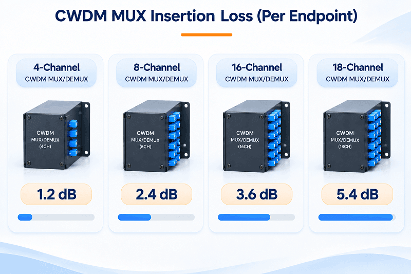
The following values are representative published maximum insertion-loss specifications for FiberMall dual-fiber configurations.
| MUX Configuration | Maximum IL per End | Maximum Loss at Both Ends |
| 4-channel | 1.2 dB | 2.4 dB |
| 8-channel | 2.4 dB | 4.8 dB |
| 16-channel | 3.6 dB | 7.2 dB |
| 18-channel | 5.4 dB | 10.8 dB |
Always verify the specifications of the exact MUX/DEMUX SKU, including any optional monitor, express, or pass-through ports.
For the complete product range, see FiberMall CWDM MUX/DEMUX.
Calculate the Optical Power Budget
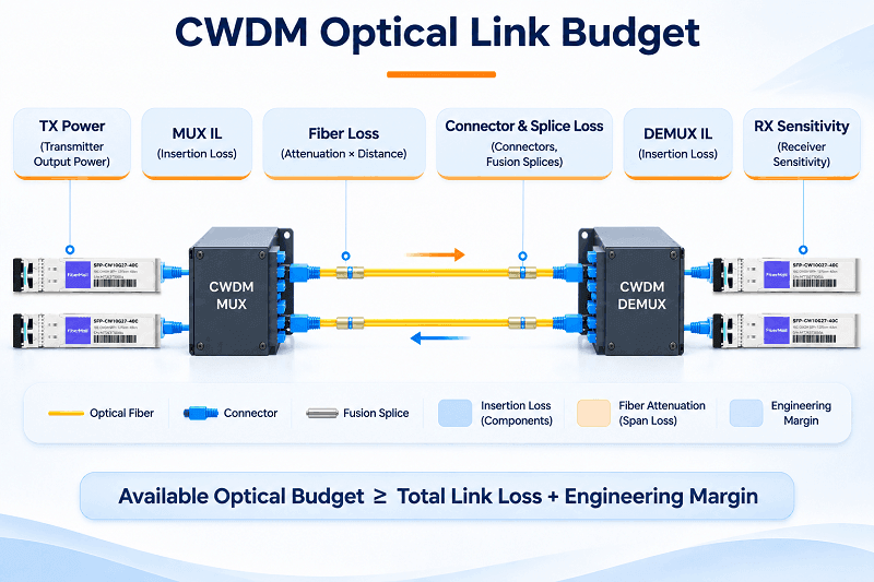
The available optical power budget can be calculated as:
Available Optical Budget = Minimum Transmitter Output Power − Receiver Sensitivity
The required optical budget must account for:
- Fiber attenuation.
- MUX/DEMUX insertion loss.
- OADM insertion loss, if applicable.
- Connector and splice losses.
- Other passive component losses.
- Engineering margin.
The design condition is:
Available Optical Budget ≥ Total Required Optical Loss + Engineering Margin
Use minimum transmitter output power rather than typical or maximum output power.
Similarly, use the receiver sensitivity and maximum input power specifications of the actual transceiver.
Example: 10G CWDM 1470 nm, 40 km-Rated Transceiver
FiberMall’s 10G CWDM SFP+ 1470 nm, 40 km product specifies:
- Minimum TX power: -1 dBm.
- Receiver sensitivity: -16 dBm.
The available optical budget is therefore:
-1 dBm − (-16 dBm) = 15 dB.
Now consider an 8-channel dual-fiber CWDM system.
The two endpoint MUX/DEMUX units introduce a combined maximum insertion loss of:
2.4 dB + 2.4 dB = 4.8 dB.
If the engineering margin is 3 dB, the remaining budget for fiber, connectors, and splices is:
15 dB − 4.8 dB − 3 dB = 7.2 dB.
This is the important result.
At a representative fiber attenuation of 0.20 dB/km around the 1550 nm region, a 40 km span would introduce approximately 8 dB of fiber attenuation alone.
That already exceeds the remaining 7.2 dB allowance, before connector and splice losses are added.
Therefore, a transceiver rated for 40 km cannot automatically be used over a 40 km span with an 8-channel MUX/DEMUX.
The complete link must be validated using the actual fiber attenuation, component specifications, and required margin.
Why a Larger MUX Can Reduce Network Reach
Consider an 18-channel MUX/DEMUX pair.
Its combined maximum insertion loss is 10.8 dB.
For a transceiver with a 15 dB available optical budget, only 4.2 dB remains before considering the engineering margin.
That leaves very little capacity for fiber attenuation, connectors, and splices.
An 18-channel MUX may therefore be unsuitable for a long-distance 10G application, even if the transceiver itself has a nominal reach of 40 km.
Choosing an 18-channel unit simply because more ports may be useful in the future can create unnecessary optical loss.
Select the MUX according to the required channel capacity and the optical loss that the link can support.
Spare Ports Do Not Inherently Increase Insertion Loss
An important distinction is the difference between reserving a MUX port and changing the optical filter architecture.
If an existing passive MUX has unused ports, activating an available wavelength does not inherently increase the insertion loss of the other channels.
You should not add an arbitrary 0.3 dB loss penalty to every existing channel simply because a spare port becomes active.
Additional loss must be evaluated when the MUX/DEMUX configuration changes or when other passive components are introduced.
Single-Fiber CWDM Requires Additional Planning
A conventional dual-fiber CWDM system uses one fiber for each transmission direction.
A single-fiber bidirectional CWDM system can reduce the fiber requirement to one strand by using complementary wavelength assignments at the two ends.
However, the system requires the correct A-side and B-side MUX/DEMUX configurations.
Its insertion loss depends on the actual filter architecture and must be checked against the relevant datasheet.
Do not assume that single-fiber CWDM has exactly twice the insertion loss of a dual-fiber system.
For a comparison of passive and active architectures, see Passive CWDM vs. Active CWDM.
Build the CWDM Bill of Materials
Once the channel plan and link budget are complete, the hardware cost can be calculated.
The following examples use FiberMall’s displayed list prices checked on November 16, 2026.
All prices are in USD and are indicative. They exclude shipping, taxes, installation, and other project-specific costs.
The BOM examples assume:
- Dual-fiber transmission.
- Two endpoint MUX/DEMUX units.
- Two optical transceivers per active wavelength channel.
- Point-to-point connectivity.
- No intermediate OADM equipment.
- All channels in each example are populated.
Reference BOM Comparison
| Design | MUX/DEMUX Pair | Optical Modules | Hardware Total | Cost per Channel | Fiber Strands |
| A. 4-channel 10G, 40 km-rated | $300 | $1,240 | $1,540 | $385 | 2 |
| B. 8-channel 10G, 40 km-rated | $560 | $2,480 | $3,040 | $380 | 2 |
| C. 4-channel 1.25G, 40 km-rated | $300 | $240 | $540 | $135 | 2 |
| D. 18-channel 1.25G, 40 km-rated | $1,260 | $1,080 | $2,340 | $130 | 2 |
The 10G examples use 1470–1610 nm CWDM SFP+ modules listed at $155 each.
The 1.25G examples use 40 km CWDM SFP modules listed at $30 each.
The MUX/DEMUX prices represent one unit at each endpoint. For example, an 8-channel unit listed at $280 requires a pair costing $560.
These are hardware price comparisons, not guaranteed maximum-reach designs. The complete optical budget must be checked before selecting a transmission distance.
Design A: Four-Channel 10G CWDM
A four-channel design operating across 1470–1530 nm requires:
- Two 4-channel MUX/DEMUX units: $300.
- Eight 10G CWDM SFP+ modules: 8 × $155 = $1,240.
Total hardware cost:
$300 + $1,240 = $1,540.
This configuration supports four independent 10G services over one fiber pair.
Design B: Eight-Channel 10G CWDM
An eight-channel design operating across 1470–1610 nm requires:
- Two 8-channel MUX/DEMUX units: $560.
- Sixteen 10G CWDM SFP+ modules: 16 × $155 = $2,480.
Total hardware cost:
$560 + $2,480 = $3,040.
The cost per active channel is $380.
The actual optical reach depends on the combined MUX/DEMUX loss and the measured fiber attenuation.
Design C: Four-Channel 1.25G CWDM
A four-channel 1.25G configuration requires:
- Two 4-channel MUX/DEMUX units: $300.
- Eight 1.25G CWDM SFP modules: 8 × $30 = $240.
Total hardware cost:
$300 + $240 = $540.
The cost per channel is $135.
Design D: Eighteen-Channel 1.25G CWDM
A full 18-channel configuration requires:
- Two 18-channel MUX/DEMUX units: $1,260.
- Thirty-six 1.25G CWDM SFP modules: 36 × $30 = $1,080.
Total hardware cost:
$1,260 + $1,080 = $2,340.
The cost per channel is $130.
This configuration offers a relatively low hardware cost per channel, but its 5.4 dB insertion loss per end must be considered carefully.
It is more suitable for applications where the measured link loss leaves sufficient optical budget.
What Does CWDM Actually Save Compared With Gray Optics?
The most useful comparison is not the price of one optical module. It is the total cost of supporting the same number of services.
Consider Design B, which carries eight independent 10G services.
With standard 10G ER optics:
- Sixteen 10G ER modules are required.
- Each module is listed at approximately $80.
- Total optical module cost: 16 × $80 = $1,280.
- Eight independent duplex links require 16 fiber strands.
With eight-channel CWDM:
- Sixteen 10G CWDM modules cost $2,480.
- The MUX/DEMUX pair costs $560.
- Total hardware cost: $3,040.
- Only two fiber strands are required.
The CWDM hardware premium is:
$3,040 − $1,280 = $1,760.
The number of fiber strands saved is:
16 − 2 = 14 strands.
The additional hardware cost per saved strand is:
$1,760 ÷ 14 = $125.71 per strand.
This is the practical economic threshold.
If providing an additional fiber strand along the same route costs more than approximately $125.71, CWDM may offer a lower overall project cost.
If spare fiber capacity is readily available and additional construction is unnecessary, standard gray optics may remain the cheaper option.
The same comparison can be performed for four-channel 10G CWDM:
- CWDM hardware total: $1,540.
- Four standard 10G ER links: $640 in optics.
- Hardware premium: $900.
- Fiber strands saved: 6.
- Additional cost per saved strand: $150.
The result depends on the wavelength band and exact transceiver SKU.
For example, FiberMall lists 10G CWDM modules in the 1270–1390 nm band at $95, while the 1470–1610 nm 40 km family is listed at $155. The equivalent 10G ER reference module is listed at $80.
Therefore, the CWDM optics premium is not a universal four-times multiplier.
It must be calculated using the actual wavelength, reach, compatibility, and product configuration.
Cost of Spare Channels
A spare wavelength should be included in the channel plan, but the purchasing strategy should distinguish between reserved ports and stocked transceivers.
For example:
- One complete 10G channel using 1470–1610 nm 40 km modules requires two transceivers: $310.
- One complete 1.25G channel using 40 km CWDM SFP modules requires two transceivers: $60.
If the MUX already has an available port, there is no need to purchase the spare modules immediately.
When the spare channel is activated, install the corresponding wavelength-matched modules at both endpoints and verify the optical budget.
What the BOM Does Not Include
A hardware-only BOM is not a complete project quotation.
Several additional items should be considered.
Patch cords
Each wavelength channel requires the appropriate connections at both endpoints.
Count the duplex patch cords required between the transceivers and MUX/DEMUX equipment.
Chassis and mounting
LGX modules may require a suitable mounting shelf or rack enclosure.
Check whether the selected configuration already includes the required mounting hardware.
OADM equipment
Linear and ring networks require additional add/drop equipment.
Include the OADM units, corresponding patch cords, and their insertion losses.
Labor and fiber preparation
Installation, fiber splicing, connector termination, testing, and commissioning can represent a significant portion of the project cost.
Acceptance testing and spare modules
Include testing equipment or service costs, and consider stocking spare modules for critical wavelength bands.
A complete quotation should separate equipment, fiber infrastructure, installation, testing, and ongoing maintenance.
Commission and Acceptance-Test the CWDM Network
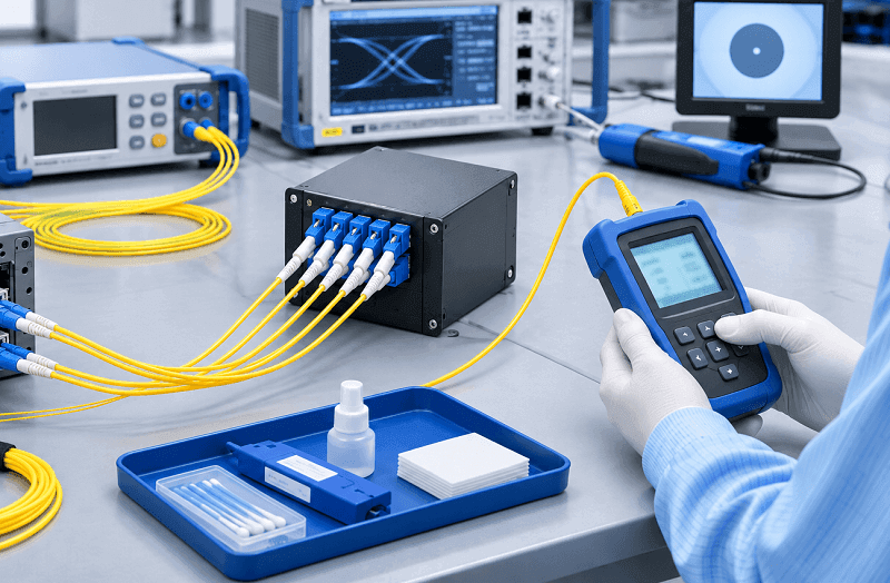
A CWDM network should be commissioned one wavelength at a time.
Installing all optical modules simultaneously and troubleshooting multiple channels afterward makes fault isolation unnecessarily difficult.
A controlled commissioning sequence is more effective.
- Inspect and clean all optical connectors.
- Install the MUX/DEMUX equipment at both endpoints.
- Verify the fiber connections and channel mapping.
- Activate the first wavelength at both endpoints.
- Measure received optical power and compare it with the engineered budget.
- Repeat the process for every active channel.
- Record the DDM baseline and final channel configuration.
CWDM Acceptance-Test Checklist
| Test Item | Acceptance Requirement |
| Received optical power | Within the transceiver’s specified operating range, with the required engineering margin |
| Per-channel insertion loss | Within the selected MUX/DEMUX and system specifications |
| Connector cleanliness | Inspected and cleaned before mating |
| DDM baseline | TX and RX optical power recorded for every module |
| Channel-to-port mapping | Matches the approved channel plan |
| End-to-end service test | All active services pass their required traffic and error tests |
Do not use a universal ±1 dB tolerance as the sole acceptance criterion.
The measured optical power must be evaluated against the actual transceiver limits and the calculated system budget.
DDM readings are also useful for ongoing maintenance.
If a receiver power reading changes significantly over time, investigate the transmitter, connectors, patch cords, fiber path, and transceiver condition.
A 3 dB change is a reason to investigate, not proof of a particular component failure.
The as-built wavelength map should be stored with the network documentation so that future maintenance teams can identify every service and optical port correctly.
Frequently Asked Questions
How many fiber strands does a CWDM network need?
A conventional dual-fiber CWDM system uses two fiber strands: one for each transmission direction.
Multiple wavelength channels can operate simultaneously over the same fiber pair.
Single-fiber bidirectional CWDM can reduce the requirement to one strand, but it requires complementary A/B MUX/DEMUX configurations and a compatible optical budget.
How many CWDM channels should I plan for?
Count the active services and add spare capacity according to the expected growth of the network.
For many small and medium deployments, two spare channels provide a practical starting point.
However, choose the MUX size according to both the required channel count and the available optical budget.
Is CWDM cheaper than gray optics?
Not necessarily.
CWDM transceivers generally have a price premium over comparable gray optics, and the system also requires MUX/DEMUX equipment.
CWDM becomes economically attractive when the value of the fiber strands it saves exceeds the additional equipment cost.
The calculation should include both optical hardware and the actual cost of providing additional fiber capacity.
Can I add CWDM channels later without downtime?
In many point-to-point configurations, additional wavelength channels can be activated through unused MUX ports without changing existing channels.
However, this depends on the MUX architecture, channel isolation, optical power levels, and the installation procedure.
A larger MUX replacement may require service interruption.
Always validate the expansion plan before deployment.
Do I need a ring topology for network protection?
Not necessarily.
A ring provides two physical paths between network locations, but a passive CWDM ring does not automatically switch traffic when a fiber fails.
If fast recovery is required, an appropriate protection mechanism must be implemented at the network or transport layer.
How much insertion loss does a CWDM MUX add?
Representative maximum insertion-loss values per end are:
- 4-channel: 1.2 dB.
- 8-channel: 2.4 dB.
- 16-channel: 3.6 dB.
- 18-channel: 5.4 dB.
For a point-to-point system, include the loss of both endpoint MUX/DEMUX units in the total link budget.
Always verify the specifications of the exact product configuration.
Conclusion: Design the Fiber Before the Optics
A successful CWDM network design begins with the existing fiber infrastructure, not the optical transceiver catalog.
Count the available strands, measure the span loss, identify existing services, and determine how many wavelength channels the network needs.
Then select the topology, assign wavelengths, calculate the complete optical budget, and build the bill of materials.
Two mistakes are particularly expensive:
- Selecting a MUX based on the number of ports you might need rather than the insertion loss your link can support.
- Assuming that a transceiver’s rated reach guarantees the same distance after MUX/DEMUX and other passive losses are included.
Both problems can be identified during the design stage.
FiberMall provides a range of passive CWDM MUX/DEMUX equipment and wavelength-specific CWDM SFP/SFP+ transceivers for different channel counts, data rates, and transmission distances.
Explore the CWDM MUX/DEMUX Product Range and CWDM SFP Product Range to identify suitable configurations.
For a project-specific design, provide FiberMall’s engineering team with:
- Available fiber strand count.
- Route length and measured span loss.
- Fiber type.
- Required services and data rates.
- Existing wavelengths and optical equipment.
- Required spare channel capacity.
The engineering team can then help develop a wavelength plan, evaluate MUX/DEMUX insertion loss, and prepare a project-specific bill of materials.
The wavelength grid is defined by ITU-T G.694.2, while optical interface applications are specified in ITU-T G.695. The current G.695 (05/2025) recommendation covers applications with up to 16 channels and up to 100 Gbit/s. An 18-channel commercial MUX configuration should therefore be evaluated against its actual component specifications rather than automatically described as an 18-channel G.695 application.
The fiber infrastructure, optical budget, and service requirements ultimately determine the right CWDM design.
Related Products:
-
 Passive CWDM Double Fiber Mux & Demux Module 18 CH (1270-1610nm) LC/UPC 1U Rack
$630.00
-
Passive CWDM Double Fiber Mux & Demux Module 16 CH (1310-1610nm) 1U Rack
$570.00
-
CWDM MUX 8CH 16 Wavelengths (TX: 1310/1330/1390/1410/1470/1490/1550/1570nm RX: 1350/1370/1430/1450/1510/1530/1590/1610nm) LC/UPC Single Fiber 1U Rack
$320.00
-
Passive CWDM Double Fiber Mux & Demux Module 8CH (1470-1610nm) LC/UPC LGX BOX
$280.00
-
CWDM MUX 4CH 8 Wavelengths (TX: 1470/1490/1510/1530nm RX: 1550/1570/1590/1610nm) with Express Port LC/UPC Single Fiber LGX BOX
$150.00
-
Passive CWDM Double Fiber Mux & Demux Module 4 CH (1470-1530nm) LC/UPC LGX BOX
$150.00
-
Passive CWDM Single Fiber 1 Channel OADM LGX BOX
$70.00
-
Passive CWDM Double Fiber 2 Channels OADM LGX BOX
$130.00
-
Passive CWDM Double Fiber 4 Channels OADM LGX BOX
$250.00
-
SFP-CW10G27-40C 10G CWDM SFP+ 1270nm 40km LC SMF DDM Transceiver Module
$95.00
-
SFP-CW10G27-10C 10G CWDM SFP+ 1270nm 10km LC SMF DDM Transceiver Module
$60.00
-
SFP-CW10G59-05C 10G CWDM SFP+ 1590nm 5km LC SMF DDM Transceiver Module
$60.00
-
SFP-CW10G27-20C 10G CWDM SFP+ 1270nm 20km LC SMF DDM Transceiver Module
$75.00
-
SFP-CW10G47-100C 10G CWDM SFP+ 1470nm 100km LC SMF DDM Transceiver Module
$280.00