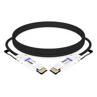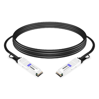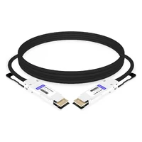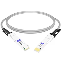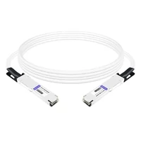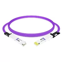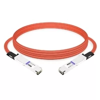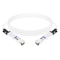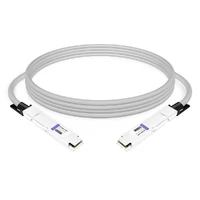

A passive DAC cable can typically reach 7–8 m at 10G, 3–5 m at 25G, 5 m at 40G, around 3 m at 50G and 200G, and approximately 2–5 m at 100G depending on the cable assembly and host platform. At 400G, passive DAC reach is generally around 2–3 m. At 800G, it is typically 1–2 m, while some 1.6T OSFP 224G passive copper assemblies support up to 1.3 m.
These figures are useful starting points, not universal guarantees. Actual DAC cable distance depends on the electrical channel budget, wire gauge, cable construction, signaling rate, FEC requirements, and host platform qualification.
A cable that works at a particular length on one switch may fail on another switch with the same connector type. Understanding the electrical specifications behind the distance rating is essential when selecting a DAC for a data center network.
How Far Can a DAC Cable Reach?
Passive DAC cables are designed for short-reach electrical connections between switches, servers, and other networking equipment. Their maximum practical reach varies by Ethernet generation, cable assembly class, and host implementation.
The following table provides an indicative overview of commonly supported passive DAC distances.
| Data Rate | Interface | Typical Passive DAC Reach |
| 10G | SFP+ | Up to 7–8 m |
| 25G | SFP28 | 3–5 m |
| 40G | QSFP+ | Up to 5 m |
| 50G | SFP56 | Up to 3 m |
| 100G | QSFP28 | Approximately 3–5 m |
| 200G | QSFP56 | Up to 3 m |
| 400G | QSFP-DD / OSFP | Approximately 2–3 m |
| 800G | QSFP-DD800 / OSFP | Typically 1–2 m |
| 1.6T | OSFP224 | Up to 1.3 m for selected products |
These distances represent typical standards-based or vendor-supported reach ranges, depending on the interface. They should not be interpreted as guaranteed maximum lengths for every cable or switch.
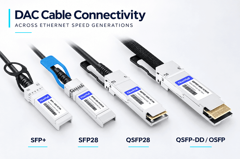
Active copper cables, including ACC and AEC, can extend the reach beyond passive DAC limits. However, the achievable distance depends on the signaling rate, active circuitry, power requirements, and platform compatibility.
For a specific installation, always verify the cable datasheet and the switch or NIC vendor’s compatibility requirements.
Need a cable length that matches your rack layout? Explore FiberMall’s passive DAC, ACC, and AEC cable solutions, with different lengths and host-compatible coding options.
DAC Cable Distance by Speed: 10G to 1.6T
The headline distance figures hide important differences between speed generations. As per-lane signaling rates increase, electrical channel requirements become more demanding, and maintaining sufficient signal margin over longer copper cables becomes increasingly difficult.
10G and 25G: The 7–8 m and 3–5 m Tiers
10G is one of the most flexible speed tiers for passive copper connectivity.
SFP+ passive DAC cables can reach approximately 7–8 m, depending on cable construction and host compatibility. Longer assemblies commonly use thicker conductors, such as 24–26 AWG, while shorter connections can use thinner cables such as 30 AWG.
For 25G SFP28, passive DAC reach depends more directly on the specified cable assembly class.
The IEEE 802.3 specifications define three 25G cable assembly classes:
- CA-25G-N: Up to 3 m, supporting operation without FEC.
- CA-25G-S: Up to 3 m, supporting BASE-R FEC and RS-FEC modes.
- CA-25G-L: Up to 5 m, requiring RS-FEC.
These classes are based on electrical performance requirements rather than length alone. A cable must meet the applicable insertion-loss and other electrical specifications to qualify for its designated class.
For longer 25G connections, verify both the cable classification and the host’s FEC capabilities.
40G and 100G: Short-Reach High-Speed Copper
40G QSFP+ passive DAC cables commonly support lengths up to 5 m under the 40GBASE-CR4 specification.
Active copper products can extend this distance. For example, some 40G active copper assemblies are available in 7 m and 10 m versions.
100G QSFP28 passive DAC cables generally support approximately 3–5 m, depending on the cable assembly and host platform.
A 5 m 100G connection requires a properly qualified cable with sufficient electrical margin. Cable gauge, insertion loss, return loss, and the host’s SerDes performance all influence whether the link operates reliably.
The difference between a 3 m and a 5 m 100G DAC is not simply the additional cable length. It also involves conductor size, cable construction, mechanical flexibility, and the electrical channel budget.
200G and 400G: PAM4 Makes Signal Integrity More Demanding
At 200G and 400G, PAM4 signaling is used to increase the amount of data transmitted per lane.
A 200G QSFP56 passive DAC typically supports up to approximately 3 m under qualified conditions.
At 400G, passive DAC reach is generally around 2–3 m, depending on the electrical interface and host platform.
For example, 400GBASE-CR4 uses four 100G electrical lanes with PAM4 signaling. The IEEE 802.3ck specification defines the corresponding high-speed electrical channel requirements.
Different 400G platforms may support different cable lengths. Some vendors qualify 2.5 m assemblies, while selected products support 3 m.
For a 400G leaf-spine connection within the same rack, passive DAC is often a practical choice when the route and platform qualification permit it.
For an adjacent-rack connection, compare a qualified passive DAC with ACC, AEC, and AOC alternatives before selecting the cable.
800G and 1.6T: Copper Reach Becomes More Limited
At 800G, passive DAC reach is typically around 1–2 m.
The electrical requirements are significantly more demanding than those of earlier generations. Cable construction, connector performance, host equalization, and channel loss all become increasingly important.
Although some vendors may offer extended-length assemblies, longer connections must be verified against the exact switch or NIC platform.
At 1.6T, OSFP224 copper connectivity uses 224G-class electrical signaling.
TE Connectivity’s OSFP 224G copper cable assemblies illustrate the reach limitations of this generation:
- Passive DAC: Up to 1.3 m.
- ACC: Approximately 1.2–2.5 m.
- AEC: Intended for connections beyond 2.5 m in TE’s product offering.
These are product-specific figures rather than universal limits for every 1.6T copper assembly.
The general trend is clear: higher per-lane signaling rates make passive copper connections more challenging. However, usable reach does not decrease according to a fixed mathematical ratio. Each generation has its own electrical specifications and implementation requirements.
Why DAC Cable Distance Shrinks as Speed Rises
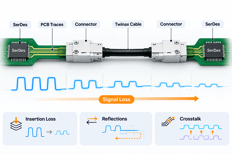
A passive DAC is an electrical transmission channel consisting of the host SerDes, PCB traces, connectors, twinaxial cable, and the receiving circuitry at the other end.
Every component contributes to the channel’s overall electrical performance. As signaling frequency increases, insertion loss and other signal-integrity challenges become more significant.
Three major factors determine how far a passive DAC can reliably transmit data.
Higher Frequencies Increase Signal Loss
Copper cable insertion loss increases with frequency.
Two important contributors are:
- Skin effect: High-frequency current tends to concentrate near the conductor surface, increasing effective resistance.
- Dielectric loss: Energy is dissipated in the insulating material surrounding the conductors.
For example, the following signaling rates illustrate how channel bandwidth requirements increase across different Ethernet generations:
| Ethernet Lane | Modulation | Symbol Rate | Nyquist Frequency |
| 25G NRZ | NRZ | 25.78125 GBd | 12.89 GHz |
| 50G PAM4 | PAM4 | 26.5625 GBd | 13.28 GHz |
| 100G PAM4 | PAM4 | 53.125 GBd | 26.56 GHz |
The Nyquist frequency is half the symbol rate for these signaling schemes.
As the signaling rate increases, the channel must maintain acceptable performance across a wider frequency range. This makes cable loss, connector quality, and host PCB design increasingly important.
That is why a cable assembly that works reliably at 10G may not meet the electrical requirements of a 100G or 400G connection, even when the physical cable construction appears similar.
PAM4 Provides Higher Bandwidth but Reduces Signal Margin
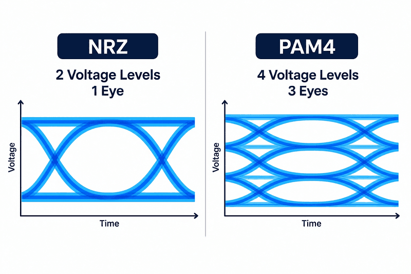
PAM4 encodes two bits per symbol using four distinct voltage levels.
Compared with NRZ, which uses two voltage levels, PAM4 carries more information per symbol and enables higher data rates without proportionally increasing the symbol rate.
However, PAM4 creates three eye openings instead of one.
At the same signal amplitude, the voltage spacing between adjacent PAM4 levels is approximately one-third of the NRZ eye height, corresponding to an approximately 9.5 dB eye-height penalty.
This reduced signal margin makes PAM4 links more sensitive to:
- Crosstalk.
- Connector reflections.
- Channel insertion loss.
- Electrical noise.
- Equalization limitations.
Consequently, high-speed PAM4 copper links require more careful electrical design, signal conditioning, and error correction.
Cable Class and FEC Affect the Supported Reach
Forward Error Correction (FEC) helps correct transmission errors and improves link reliability.
For 25G copper Ethernet, IEEE defines different cable assembly classes with corresponding electrical performance requirements and FEC capabilities.
| Cable Class | Maximum Insertion Loss at 12.8906 GHz | Supported FEC Modes | Reference Reach |
| CA-25G-N | 12.98 dB | No FEC | Up to 3 m |
| CA-25G-S | 16.48 dB | BASE-R FEC / RS-FEC | Up to 3 m |
| CA-25G-L | 22.48 dB | RS-FEC | Up to 5 m |
These figures apply to the specified 25G cable assembly classes. They should not be generalized to all Ethernet speeds.
The cable assembly’s EEPROM may contain identification and compliance information that helps the host identify the connected cable. However, how a switch or NIC uses this information depends on the platform implementation.
Some systems support automatic FEC negotiation, while others require manual configuration.
An incorrect FEC configuration or insufficient electrical channel margin can cause link initialization failures, elevated error rates, or uncorrectable errors under sustained traffic.
FEC improves error tolerance, but it cannot compensate for an electrically non-compliant cable or an incompatible host interface.
Passive vs. Active DAC Distance: What Signal Conditioning Buys
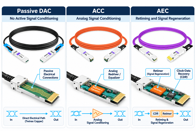
Passive DAC cables contain no active signal-conditioning electronics. The host SerDes performs the required transmission equalization and reception processing.
This makes passive DACs attractive for short connections because they typically offer low cable-side power consumption, low cost, and simple installation.
Active copper cables introduce electronic circuitry to improve signal quality and extend reach.
There are two commonly used categories:
ACC (Active Copper Cable)
ACC typically uses analog signal-conditioning components, such as redrivers or equalizers, to compensate for channel loss and improve signal integrity.
Compared with passive DAC, ACC can support longer connections while retaining a copper-based architecture.
AEC (Active Electrical Cable)
AEC often uses more advanced signal-conditioning circuitry, including retimers with clock and data recovery, to regenerate the electrical signal.
AEC is commonly used when a passive DAC or ACC cannot provide sufficient electrical margin over the required distance.
The exact internal architecture, power consumption, and supported reach vary by manufacturer and product generation. ACC and AEC should therefore be evaluated using the actual product specifications rather than assuming that all vendors use identical implementations.
The additional reach comes with trade-offs:
- Higher power consumption than passive DAC.
- Higher purchase cost.
- More complex internal electronics.
- Additional compatibility and qualification requirements.
For a deeper comparison, see our guide to passive vs. active DAC cables.
Where DAC Cable Distance Ends: AOC and Optical Transceivers
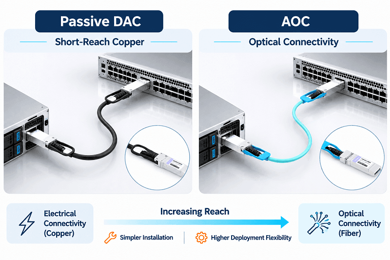
When a copper cable cannot meet the required distance or electrical performance, optical connectivity becomes the next option.
The practical selection process can be summarized as follows:
- Short in-rack connections: Use passive DAC when the cable meets the electrical and platform requirements.
- Extended copper connections: Consider ACC or AEC when a qualified active copper product supports the required distance.
- Longer connections or cross-rack deployments: Consider AOC or optical transceivers with fiber.
- Extended-distance infrastructure: Use optical transceivers and the appropriate fiber type when required by the application.
AOC offers several advantages:
- Lower cable weight than many comparable copper assemblies.
- Immunity to electromagnetic interference along the optical transmission path.
- Flexible routing in dense equipment racks.
- Availability in different optical reach configurations.
Optical transceivers with separate fiber cables provide additional flexibility for network upgrades, cable replacement, and longer-distance connectivity.
The decision is not based on reach alone. Cost, power consumption, cable management, airflow, installation complexity, and future scalability should also be considered.
For a more detailed comparison, see our guide to DAC vs. AOC cables. For QSFP-DD-specific cable lengths and breakout configurations, refer to the QSFP-DD cable guide.
How to Measure DAC Cable Length for a Real Installation
One common reason for DAC compatibility and installation problems is ordering a cable based on the straight-line distance between two devices.
A cable must follow the actual installation route, not the distance shown in a network diagram.
Measure the Routed Path, Not the Straight Line
Measure the complete cable route, including:
- The vertical drop from the switch port.
- The horizontal path through the cable management system.
- The turns and bends around rack structures.
- The route into the server or network appliance.
- The service loop required at both ends.
A measuring tape or a temporary cable can help establish the actual routed distance.
Add an appropriate installation and maintenance allowance based on the rack layout. Avoid applying a fixed percentage without considering the actual routing requirements.
AWG, Cable Diameter, and Bend Radius
Wire gauge is an important factor in passive DAC performance.
A lower AWG number indicates a thicker conductor. Thicker conductors generally have lower electrical resistance and can help reduce cable loss.
However, thicker cables also tend to have larger outside diameters and may be less flexible.
| Wire Gauge | General Characteristics | Installation Considerations |
| 30 AWG | Thin and lightweight | Easier routing, generally suited to shorter qualified connections |
| 28 AWG | Intermediate conductor size | Balances cable flexibility and electrical performance |
| 26 AWG | Thicker conductor | Often used for longer qualified passive DAC assemblies, but requires more installation space |
Actual cable diameter and minimum bend radius depend on the complete cable construction, including insulation, shielding, and outer jacket materials.
Before ordering, check the manufacturer’s datasheet for:
- Cable outside diameter (OD).
- Minimum static bend radius.
- Minimum dynamic bend radius, if specified.
- Connector dimensions.
- Recommended cable management clearance.
A cable that meets the electrical length requirement but exceeds its minimum bend radius may suffer mechanical damage or degraded signal integrity.
Host Qualification Matters as Much as Length
Two switches with the same port type can have different SerDes characteristics, PCB losses, equalization capabilities, and FEC configurations.
As a result, the same DAC cable may work on one platform but fail to establish a reliable link on another.
When specifying a DAC cable, provide the supplier with:
- Switch or NIC manufacturer and model.
- Port type and supported data rate.
- Required cable length.
- Cable type: passive DAC, ACC, or AEC.
- Required EEPROM coding.
- FEC and auto-negotiation requirements.
A qualified cable assembly with the correct EEPROM coding is generally a more reliable choice than a generic cable selected solely by connector type and physical length.
A Step-by-Step DAC Cable Length Selection Checklist
Before ordering a DAC cable, follow these steps:
- Confirm the data rate, electrical interface, and connector type at both ends.
- Measure the complete routed cable path, including service loops.
- Select the appropriate cable type: passive DAC, ACC, AEC, or AOC.
- Choose a cable construction and wire gauge that meet the required electrical specifications.
- Confirm the applicable cable class, FEC mode, and host compatibility.
- Check the switch or NIC vendor’s qualification list for the exact cable length and coding.
- Verify link status, negotiated speed, FEC counters, and error statistics after installation.
- Label both cable ends and keep suitable spare assemblies for maintenance.
Following this process helps reduce cable replacement, installation delays, and unexpected link failures.
DAC Cable Distance in AI Data Centers
AI data centers place increasingly demanding requirements on high-speed interconnects.
Modern AI systems use different copper and optical connectivity technologies depending on whether the connection belongs to the scale-up fabric or the scale-out network.
Copper Connectivity in NVIDIA GB200 NVL72 Systems
The NVIDIA GB200 NVL72 architecture uses more than 5,000 high-performance copper cables in its NVLink interconnect system.
These cables connect GPUs and NVLink switches through a dedicated rack-scale interconnect architecture.
It is important to distinguish these specialized NVLink copper assemblies from conventional Ethernet passive DAC cables. They serve different electrical interfaces and should not be treated as interchangeable products.
The example demonstrates why copper remains important in high-density AI systems: short, carefully engineered electrical connections can provide high bandwidth without requiring optical conversion at every connection.
Scale-Up vs. Scale-Out Connectivity
AI data center connectivity generally involves two different networking requirements.
Scale-Up Connectivity
Scale-up networks connect GPUs and dedicated accelerator interconnect switches within a tightly integrated system.
Specialized high-bandwidth copper interconnects are commonly used where the electrical distance is short and the platform is specifically designed for the connection.
Scale-Out Connectivity
Scale-out networks connect servers, GPU systems, and network switches through Ethernet or InfiniBand fabrics.
Depending on the data rate, distance, and network architecture, these connections may use:
- Passive DAC for short electrical connections.
- ACC or AEC for extended copper connections.
- AOC for integrated optical connectivity.
- Optical transceivers with fiber for longer or more flexible network links.
The correct choice depends on the physical topology, required bandwidth, host compatibility, and cable qualification.
Power and Cooling Considerations
Cable-side power consumption is another important consideration in dense AI data centers.
Passive DAC cables contain no active signal-conditioning electronics, so the cable itself has no active electronics power draw.
ACC and AEC assemblies require power for their internal electronic components. Optical transceivers also consume power for optical and electrical signal conversion.
Actual power consumption varies by product, data rate, and implementation. Comparisons should use equivalent measurement boundaries, such as per cable end or per complete link.
Cable diameter and routing also affect rack-level airflow and serviceability. In high-density environments, selecting cables that balance electrical performance, flexibility, and physical dimensions can simplify installation and maintenance.
FiberMall supplies passive DAC, ACC, and AEC assemblies for high-speed data center connectivity, including 400G QSFP-DD copper cable solutions.
If you are selecting copper or optical connectivity for an AI network, start by identifying the electrical interface, actual cable route, required distance, and host platform qualification.
For more information, see our guide to what a DAC cable is.
DAC Cable Distance FAQ
What is the maximum distance for a DAC cable?
There is no single maximum distance for all DAC cables.
Typical passive DAC reach varies by data rate:
- 10G: Approximately 7–8 m.
- 25G: Approximately 3–5 m.
- 40G: Up to 5 m.
- 50G: Up to 3 m.
- 100G: Approximately 3–5 m.
- 200G: Up to 3 m.
- 400G: Approximately 2–3 m.
- 800G: Typically 1–2 m.
- 1.6T: Up to 1.3 m for selected passive products.
The actual maximum depends on cable construction, electrical specifications, FEC requirements, and host qualification.
How far can a 10G DAC cable run?
A 10G SFP+ passive DAC can typically reach approximately 7–8 m, depending on the cable assembly and host platform.
Thicker conductors, such as 24–26 AWG, are commonly used for longer assemblies, while thinner 30 AWG cables are generally suited to shorter connections.
Active copper solutions may support longer distances.
Can a DAC cable be 10 meters?
A 10 m passive DAC is generally outside the common reach range of mainstream high-speed Ethernet DAC products.
For a 10 m connection, consider an active copper cable or AOC, depending on the data rate and platform compatibility.
At higher data rates, AOC or optical transceivers with fiber are often more practical choices.
Is a 5 m DAC better than a 10 m AOC?
Neither option is universally better. The choice depends on the application.
A 5 m passive DAC is generally attractive when the link is electrically qualified and low cost and low cable-side power consumption are priorities.
A 10 m AOC may be more suitable when lighter cable routing, electromagnetic immunity, or greater physical flexibility is important.
At 100G, a 5 m DAC must meet the applicable electrical specifications and host qualification requirements. At 400G and 800G, a 5 m passive DAC is generally outside typical product reach, making AEC or AOC more practical options.
What is the maximum length of a 400G DAC?
A 400G QSFP-DD or OSFP passive DAC typically supports approximately 2–3 m, depending on the electrical interface and vendor qualification.
Some platforms support 2.5 m assemblies, while selected products support 3 m.
Always verify the switch or NIC datasheet and the cable manufacturer’s qualification information before ordering.
Why does my 3 m DAC work on one switch but not another?
The same cable may behave differently on two switches because their electrical channel designs are not identical.
Important differences include:
- SerDes equalization capabilities.
- Host PCB insertion loss.
- Connector and port characteristics.
- FEC configuration.
- Cable EEPROM coding and compatibility requirements.
A cable that works on one platform may not provide sufficient signal margin on another.
Check the cable qualification list, verify FEC settings, and review the host’s link diagnostics before replacing the cable.
Related Products:
-
 QDD-200G-PC50CM 0.5m (1.6ft) 200G QSFP-DD to QSFP-DD Passive Direct Attach Copper Twinax Cable
$45.00
-
QSFP56-200G-PC50CM 0.5m (1.6ft) 200G QSFP56 to QSFP56 PAM4 Passive Direct Attach Copper Twinax Cable
$45.00
-
QSFPDD-400G-PC50CM 0.5m (1.6ft) 400G QSFP-DD to QSFP-DD PAM4 Passive Direct Attach Copper Twinax Cable
$70.00
-
QSFP-DD-400G-AC3M 3m (10ft) 400G QSFP-DD to QSFP-DD PAM4 Active Direct Attach Copper Twinax Cable
$350.00
-
QDD-OSFP-FLT-PC50CM 0.5m (1.6ft) 400G QSFP-DD to OSFP Flat Top PAM4 Passive Direct Attached Cable
$154.00
-
OSFP-FLT-400G-PC50CM 0.5m (1.6ft) 400G NDR OSFP to OSFP PAM4 Passive Direct Attached Cable, Flat top on one end and Flat top on other
$110.00
-
QDD-OSFP-FLT-AEC50CM 0.5m (1.6ft) 400G QSFP-DD to OSFP Flat Top PAM4 Active Electrical Copper Cable
$1200.00
-
OSFP-FLT-800G-AC3M 3m (10ft) 800G Twin-port 2x400G OSFP to 2x400G OSFP InfiniBand NDR Active Copper Cable, Flat top on one end and Flat top on the other
$600.00
-
OSFP-FLT-800G-PC2M 2m (7ft) 2x400G OSFP to 2x400G OSFP PAM4 InfiniBand NDR Passive Direct Attached Cable, Flat top on one end and Flat top on the other
$300.00
-
OSFP-800G-PC50CM 0.5m (1.6ft) 800G Twin-port 2x400G OSFP to 2x400G OSFP InfiniBand NDR Passive Direct Attach Copper Cable
$105.00