Data Center Network (DCN) Demand Evolution
The network is a crucial component of IT infrastructure, serving as the foundation that connects all IaaS layer resources to provide services. In the era of data, the core of cloud computing, big data, and artificial intelligence is data itself, with the network acting as the high-speed highway that carries data flow.
The data center networks have undergone remarkable changes over the past decade, evolving from the stringent and standardized data centers of the financial industry to the current internet companies leading the technological wave.
Today, with the rapid development of cloud-native technologies, which encompass over 200 projects, the development, deployment, operation, and maintenance of applications have transformed. A multitude of application systems are built using cloud-native technologies, with containers serving as the smallest unit of business workload, characterized by agility, consistency, and strong replication and scaling capabilities. Clusters composed of numerous containers far exceed the number in VMs. Additionally, finer-grained resource allocation mechanisms and reliability distribution strategies have led to more frequent cross-node communication and interaction between business containers and various distributed system components. These rely on external networks to provide reliable end-to-end forwarding, raising higher demands for traffic control and visualization.
Furthermore, with the widespread adoption of big data and artificial intelligence technologies, systems based on these, such as recommendation engines, image search and recognition, voice interaction, and machine translation, have been extensively applied. Big data and AI have become vital tools for business management and market competition, with massive amounts of data being stored for analysis and mining. From data processing and model training (machine learning/deep learning) to online services, each step relies on powerful computing and vast data, increasing computational and storage resource consumption. This has prompted the evolution of data center construction towards large-scale and super-large-scale, with the accompanying network scale also growing, making network automation and intelligent operation a necessity.
Lastly, it’s important to mention the explosive growth of long and short videos, live streaming, VR/AR, and other video-streaming media in the past two years. These have penetrated various fields such as news, education, shopping, socializing, travel, and gaming entertainment, with a vast user base and high usage duration. Coupled with the rapid proliferation of 5G terminals, users’ expectations for high-quality videos and low-latency viewing experiences continue to rise, further driving network bandwidth consumption.
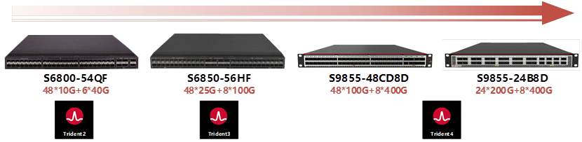
In response to the changing trends in business requirements and the rapid development of network technology, the iteration speed of data center network equipment has also accelerated. Currently, data center switches are updated with a new generation of products every two years, and each new generation offers nearly double the performance, higher throughput, larger table entries, and more features, with a more targeted role positioning in the network.
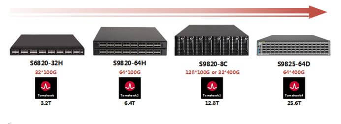
Driven by the overall industry environment of server-side network cards and optical modules, the bandwidth of data center access links has evolved from 10G -> 25G -> 50G -> 100G -> 200G -> 400G, and the interconnect link bandwidth has evolved from 40G -> 100G -> 200G -> 400G -> 800G. The main scenario has shifted from a 25G access + 100G interconnect combination to the current 100G access + 400G interconnect combination. In GPU scenarios, access will develop from 100G, 200G to 400G, 800G.
Considering the aforementioned context and looking at network architecture, the choice of DCN network architecture is influenced by many factors such as business requirements, current technological conditions, equipment costs, management costs, and human resource investment. There is no single architecture that can cater to all customer scenarios and needs; a comprehensive consideration and balance must be made before making a choice.
Two-Tier Clos Architecture: Suitable for Small to Medium-Sized Data Centers
The two-tier Clos architecture is one of the earliest and most widely applied network structures, and it remains the preferred choice for many industry clients to this day. The network equipment only plays two roles, ensuring short data forwarding paths, with cross-leaf accessibility within one hop, and offering strong consistency in paths and latency. The unified access approach greatly facilitates deployment and horizontal scaling, such as the deployment of BGP protocols, policy control, routine maintenance, and troubleshooting. It is particularly well-suited for small to medium-sized enterprises with fewer operational staff.
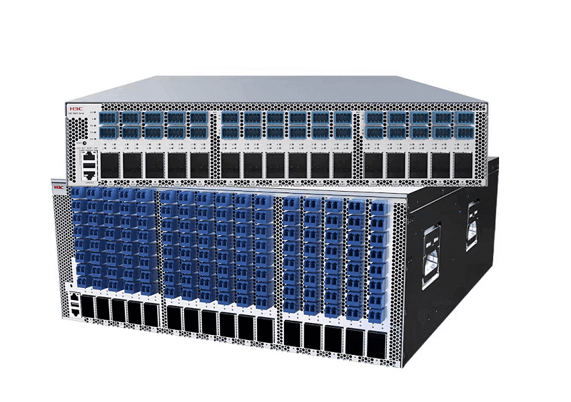
The two-tier Clos architecture places high demands on the performance and reliability of Spine switches, typically employing data center chassis-based core switch products. With variable cell forwarding and VoQ scheduling mechanisms, it ensures strict non-blocking switching within Spine devices, and the configuration of distributed large caches naturally excels in handling traffic bursts. Chassis-based core switches have independent control planes, forwarding planes, and support systems, and they use redundant designs, making the entire system far more reliable than box-type switches.
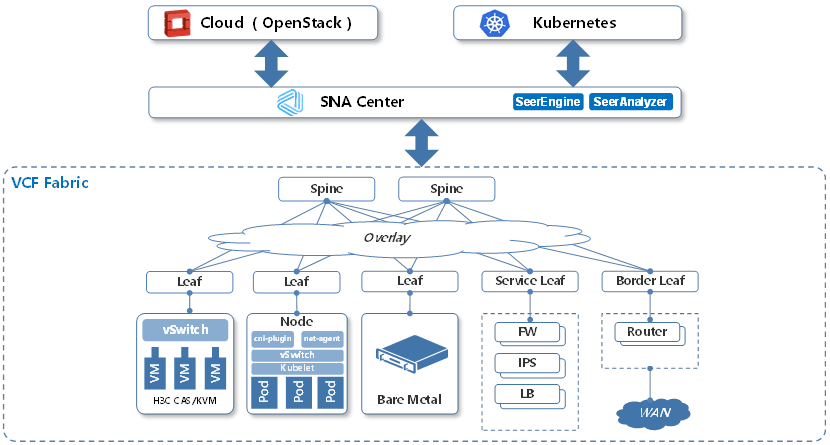
The two-tier Clos architecture is more mature in its compatibility with commercial SDN controller solutions. Combined with an SDN controller, it can quickly build network Overlay solutions based on EVPN, reducing the complexity of deploying east-west and north-south service chains and meeting the network’s demand for full-form computing resource linkage, such as VMs, bare metal, and containers, in cloud scenarios.
Additionally, this architecture is also suitable for large enterprises deploying convergence rooms and edge rooms in various locations to build edge computing networks, alleviating backbone network pressure and reducing access latency.
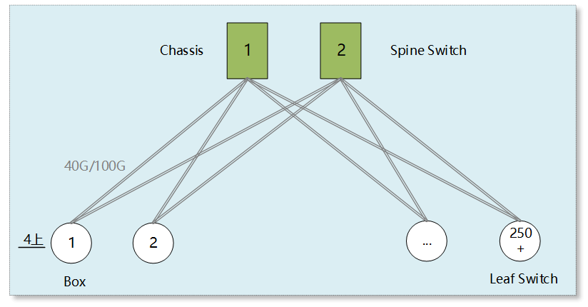
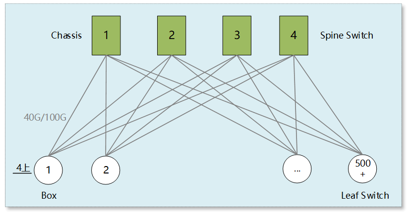
Spines use either 2 or 4 chassis-based core switches, and each Leaf switch has 4 uplinks. Ensuring a 3:1 convergence ratio (10G Leaf with 440G uplinks, 4810G downlinks; 25G Leaf with 4100G uplinks, 4825G downlinks), the supported server scale (dual uplink) can reach over 5000 and 10000, respectively.
As seen from the topology, the network scale, or horizontal expansion capability, of the two-tier Clos architecture is limited by the total number of ports provided by the Spine devices (number of devices * ports per device). Since the number of uplink ports on Leaf switches is fixed (usually 4-8), the number of Spine layer switches is also limited and cannot be continuously increased.
Three-Tier Clos Architecture: Suitable for Large-Scale and Hyper-Scale Data Centers
The server scale supported by the two-tier Clos architecture generally does not exceed 20,000 units. The introduction of the three-tier Clos architecture resolves the bottleneck in the network scale presented by the two-tier architecture. The three-tier Clos architecture adds a layer of aggregation switches (Pod Spine) between the two existing layers. A group of Pod Spine switches, along with all connected Leaf switches, form a Pod. Multiple Pods are interconnected through the Spine layer switches to compose the entire network. Increasing the number of Pods allows for horizontal scaling of the network, significantly enhancing its expansion capability. Moreover, deploying services by Pod unit offers greater flexibility in adapting to various business needs, providing differentiated services, and ensuring isolation.

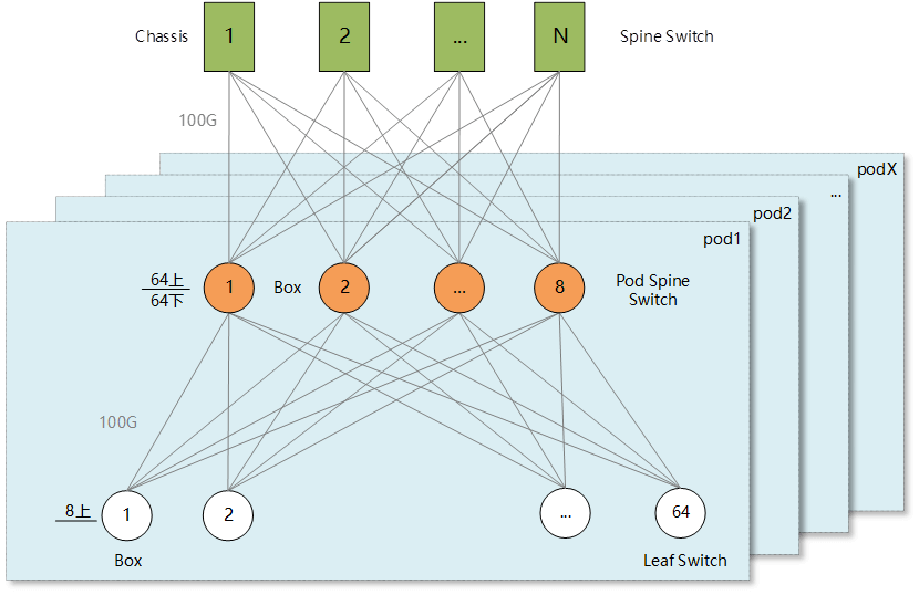
Within each Pod of the three-tier Clos architecture, the Pod Spine employs either four or eight high-density 100G box-type switches. Half of the Pod Spine’s ports are used to connect upwards to the Spine, and the other half to connect downwards to the Leaf switches. Each Leaf switch has either four or eight uplinks. Typical scenarios are as follows:
Scenario A: The Pod Spine uses four 64-port 100G box-type switches (S9820-64H). Each Leaf switch has four uplinks. With a 3:1 convergence within the Pod (25G Leaf with 4100G uplinks, 4825G downlinks), a single Pod can support a server scale of 768 units with dual uplinks.
Scenario B: The Pod Spine uses eight 128-port 100G box-type switches (S9820-8C). Each Leaf switch has eight uplinks. With a 1.5:1 convergence within the Pod (25G Leaf with 8100G uplinks, 4825G downlinks), a single Pod can support a server scale of 1536 units with dual uplinks. With a 1:1 convergence (25G Leaf with 8100G uplinks, 3225G downlinks), a single Pod can support a server scale of 1024 units with dual uplinks.
The introduction of the high-density aggregation switch Pod Spine has allowed the Spine layer’s rack-type core switches to exceed limitations, enabling the deployment of dozens of units. The total number of ports provided by the Spine layer’s rack-type core switches can be used to connect dozens of Pods, allowing the entire network to support a server scale of over 100,000 units.
Furthermore, by adjusting the ratio of uplink and downlink ports within the Pod Spine switches, it is possible to flexibly define the convergence ratio for each Pod. This not only meets different business needs but also helps reduce costs and avoid unnecessary waste.
Multi-Tier Clos Architecture: Suitable for Large-Scale and Hyper-Scale Data Centers
The multi-plane networking architecture based on box-type devices is the latest architecture adopted by leading internet companies for constructing large-scale and hyper-scale data center networks. This architecture originated from Facebook’s F4. The two generations of switches used to build this network, the 6-pack and Backpack, were based on a multi-chip (12 chips) design, which made management and deployment inconvenient and costly. With the evolution from F4 to F16, thanks to the improvement in chip capabilities, the Minipack switch used to build F16 adopted a single-chip design, significantly reducing power consumption, cost, and technical barriers. The solution became more mature, and since then, this architecture has been introduced by internet companies in China.
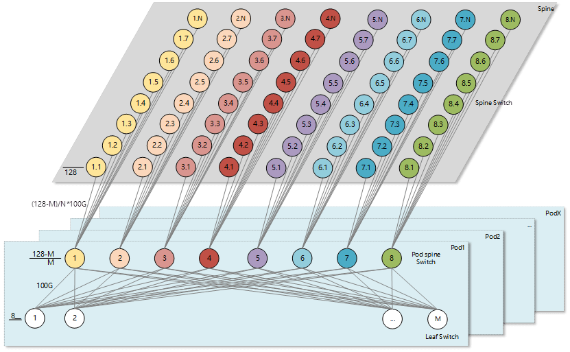
The papers “Introducing Data Center Fabric, the Next-generation Facebook Data Center Network” and “Reinventing Facebook’s Data Center Network” provide detailed explanations of this architecture. Compared to the three-tier Clos architecture, the multi-plane networking architecture based on box-type devices replaces the Spine layer’s rack-type switches with box-type switches, thus all layers of the network are composed of box-type switches. In terms of device connectivity, unlike the three-tier Clos architecture where each Pod Spine needs to have fully meshed with all Spine layer switches, the new architecture divides the Spine layer switches into multiple groups (the number of groups corresponds to the number of Pod Spine switches in each Pod). Each group of Spine switches forms a plane (as shown in the figure, the Spine layer is divided into 8 planes, distinguished by different colors), and each Pod Spine switch only needs to be fully meshed with the Spine switches in the corresponding plane. This allows the entire Spine layer to connect more Pods, building a hyper-scale data center that supports hundreds of thousands of servers. Moreover, as the performance of box-type switches improves, this architecture can continue to expand its capacity.
A core chassis switch S12516X-AF with a fully equipped 48-port 100G service board, along with six box switches S9820-8C with 128 ports of 100G each, can both provide the same number of 100G ports (768 in total). However, opting for the box switch solution offers significant cost, power consumption, and heat dissipation advantages. It also eliminates the special requirements for cabinet space and power distribution that traditional core chassis switches necessitate.
Since both the Spine and Pod Spine utilize identical equipment with consistent functionality and forwarding delay, it facilitates the development of new features and seamless deployment of applications across the entire network. Moreover, the network can smoothly transition from 100G networking to 200G, 400G, and future higher-speed networking in sync. Furthermore, due to the single-chip design, the entire Spine layer constructed with box switches exhibits significantly lower forwarding latency compared to using chassis devices, further reducing access latency across Pods.
Nevertheless, this architecture introduces new challenges. The quantity of Spine layer devices is significantly higher than when using chassis switches, and the individual reliability of box switches is lower than that of core chassis switches, posing substantial challenges for network management and daily operations. Supporting management platforms, monitoring systems, and more must be adaptable to these changes. This necessitates heightened requirements for network operations teams, including refined personnel division, extensive operational experience, robust technical skills, platform development capabilities, and overall network control to mitigate and reduce the impact of equipment and network failures on business operations.
The three most typical DCN network architectures have been introduced above. Effectively managing these networks requires the utilization of network visualization technology. Network visualization technology not only enables end-to-end traffic monitoring, and risk alerting, and assists in troubleshooting but also, through data accumulation and analysis, can guide and optimize the network architecture design of data centers (such as models, convergence ratios, and POD scales), making it a crucial technical tool.
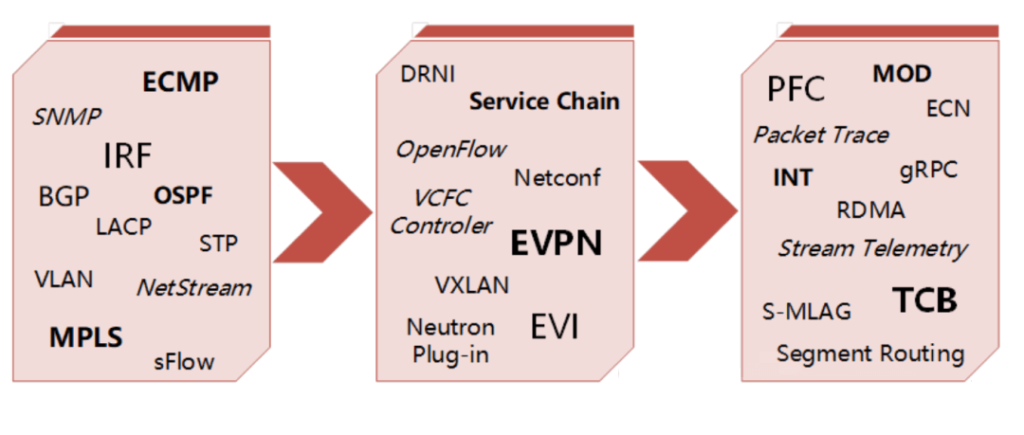
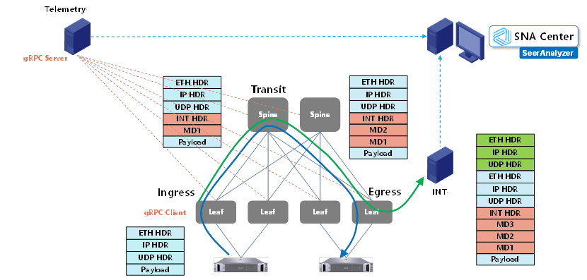
Network visualization technology is becoming increasingly proactive, efficient, and intelligent. For instance, utilizing gRPC allows for real-time and high-precision collection of various information from devices. INT or Telemetry Stream can be used to obtain the path and latency of business data transmission in the network. TCB enables monitoring of device MMUs to capture queue packet loss time, reasons, and discarded packets. MOD can detect packet loss occurring during internal device forwarding processes and capture the reasons for packet loss and the characteristics of discarded packets. Packet Trace allows for in-depth analysis of forwarding logic, simulating packet forwarding within chips to identify root causes of issues.
In the future, intelligent NICs will play a significant role in DCN networks. Intelligent NICs with programmable capabilities not only free up CPU resources and achieve high-performance forwarding but also offer functions such as tunnel encapsulation/decapsulation, virtual switching, encryption/decryption, RDMA, etc. With increasing business scenarios and demands, more data plane functions will be handled by intelligent NICs, breaking the limitations of server- or switch-based implementations. This shift aims to achieve a perfect balance of performance, functionality, and flexibility. Intelligent NICs will replace Leaf switches at the furthest end of DCN networks. Consequently, network architecture, protocol deployment, visualization technology, etc., will change with the introduction of intelligent NICs, facilitating end-to-end performance optimization and service assurance, end-to-end detection and monitoring, and the application of new technologies like SRv6. The future DCN networks will advance to provide more stable, efficient, and flexible network services for increasingly diverse upper-layer businesses.
Related Products:
-
 NVIDIA MMS1Z00-NS400 Compatible 400G NDR QSFP112 DR4 PAM4 1310nm 500m MPO-12 with FEC Optical Transceiver Module
$850.00
NVIDIA MMS1Z00-NS400 Compatible 400G NDR QSFP112 DR4 PAM4 1310nm 500m MPO-12 with FEC Optical Transceiver Module
$850.00
-
NVIDIA MMS4X00-NS400 Compatible 400G OSFP DR4 Flat Top PAM4 1310nm MTP/MPO-12 500m SMF FEC Optical Transceiver Module
$700.00
-
NVIDIA MMA1Z00-NS400 Compatible 400G QSFP112 VR4 PAM4 850nm 50m MTP/MPO-12 OM4 FEC Optical Transceiver Module
$550.00
-
NVIDIA MMA4Z00-NS400 Compatible 400G OSFP SR4 Flat Top PAM4 850nm 30m on OM3/50m on OM4 MTP/MPO-12 Multimode FEC Optical Transceiver Module
$550.00
-
NVIDIA MMS4X00-NM-FLT Compatible 800G Twin-port OSFP 2x400G Flat Top PAM4 1310nm 500m DOM Dual MTP/MPO-12 SMF Optical Transceiver Module
$1199.00
-
NVIDIA MMA4Z00-NS-FLT Compatible 800Gb/s Twin-port OSFP 2x400G SR8 PAM4 850nm 100m DOM Dual MPO-12 MMF Optical Transceiver Module
$650.00
-
NVIDIA MMS4X00-NM Compatible 800Gb/s Twin-port OSFP 2x400G PAM4 1310nm 500m DOM Dual MTP/MPO-12 SMF Optical Transceiver Module
$900.00
-
NVIDIA MMA4Z00-NS Compatible 800Gb/s Twin-port OSFP 2x400G SR8 PAM4 850nm 100m DOM Dual MPO-12 MMF Optical Transceiver Module
$650.00
-
NVIDIA MCA4J80-N003 Compatible 800G Twin-port 2x400G OSFP to 2x400G OSFP InfiniBand NDR Active Copper Cable
$600.00
-
NVIDIA MCP7Y00-N001 Compatible 1m (3ft) 800Gb Twin-port OSFP to 2x400G OSFP InfiniBand NDR Breakout Direct Attach Copper Cable
$160.00