
Layer 3 switch, very powerful, is an upgraded product of layer 2 switch. It has all the functions of the switch, and some of the functions of the router. It is a device to achieve high-speed data forwarding in the local area network. Next, let’s take a closer look at the next layer 3 switch.
What is a Layer 3 Switch?
Layer 3 switch is a network device with a routing selection function created on the basis of a Layer 2 switch. It can implement network functions and forward packets based on ASIC and FPGA. Layer 2 switch performs the data frame or VLAN transmission function based on the MAC address of the data link layer. Layer 3 switch performs the routing selection and packet filtering functions based on the IP address of the network layer.
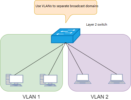
Layer 2 switch
Layer 2 switch: By using VLANs to separate broadcast domains, terminals under the same VLAN can exchange data frames. When there is a need for communication between terminals of different VLANs, the routing function must be used, that means to add an additional router.
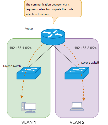
Layer 2 switch 2
Layer 2 switches and routers are used in combination to complete Cross-VLAN communication, while layer-3 switches can directly complete the communication between different VLANs without other network equipment.
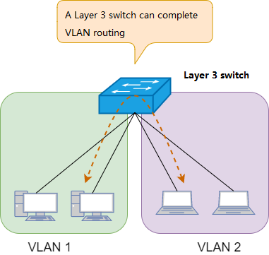
Layer-3 switch
At present, the internal network core switches are all using Layer 3 switches. Layer 3 switch is used to forward packets within the Intranet composed of Ethernet, while router is used as a gateway between the Internet and the intranet.
What is the Difference between Layer 3 Switches and Routers?
Layer 3 Switch vs Switch
Layer 3 switch only support the data link layer protocol of Ethernet and the network layer protocol of IP network.
Router: In addition to the IEEE 802 standard, the physical layer and data link layer also support other protocols, including ATM, SDH, and serial ports. The network layer and transport layer also support protocol stacks other than TCP/IP, such as IPX, AppleTalk, and so on. These functions are completed by software running on the CPU, compared to the layer 3 switch, the speed will be much slower. but there are also many functions that must be handled by the router CPU, such as remote access, security functions, etc.
What is the Architecture of the Layer 3 Switch?
The constituents of a layer 3 switch include control plane, data plane, backplane, and physical interfaces. The same architecture applies to high-end routers and firewalls. The three-layer switch divides the interior of the hardware device into two areas, that is, the control plane mainly with routing and management functions and data plane mainly with data-forwarding functions, so as to realize the system architecture of high-speed packet forwarding.
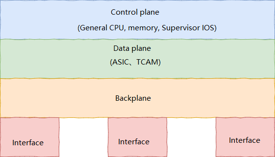
Components of Layer-3-Switch -1
Components of Layer-3-Switch-2
When the internal structure of the hardware is divided into a control plane and a data plane, the transmission of packets requires the use of FIB (forwarding information base) and adjacency table information. This method of IP packet transmission using FIB and adjacency table information is called express forwarding.
FIB and Adjacency table
Routers use CPU for packet forwarding, while Layer 3 switches use ASCI instead of the CPU for faster packet forwarding.
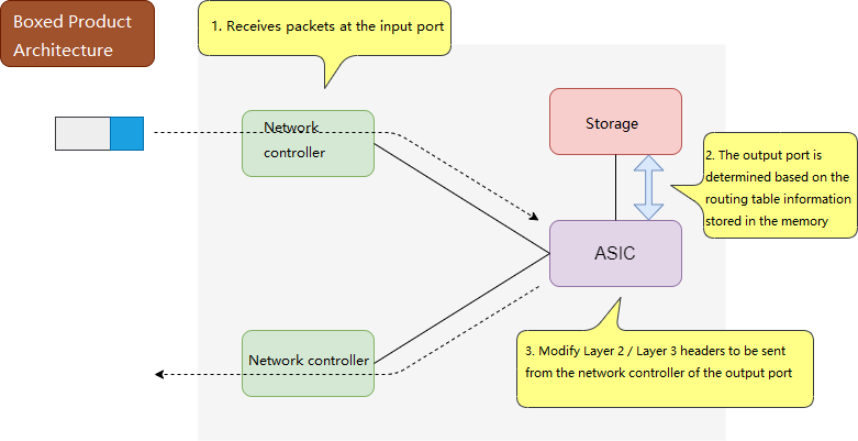
Boxed product architecture 1
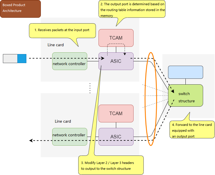
Boxed product architecture 2
Layer 3 switches combine the FIB and adjacency tables into a single entry called the FDB (forwarding database), which is registered in memory and processed by hardware for high-speed retrieval.
What is Multilayer Switching?
Except for layer 2 switches, switches above layer 3 (inclusive) are collectively referred to as multilayer switches. A layer-3 switch that has network functions such as IP routing and can control the access to the TCP port number of the transport layer through the access control list, also called Layer 4 switch. A switch that can support access control up to the TCP level is called a Layer 4 switch. A switch that can perform load balancing and other operations based on the application layer parameters of HTTP and HTTPS is called Layer 7 switch. Some manufacturers distinguish between network devices and routers that deal with the application layer as different types of products. But the so-called multi-layer switch is a high-speed network equipment for business processing of each layer based on ASIC and FPGA hardware processing.
What is a Load Balancing Device?
Multiple clients connecting to a server at the same time can cause overloaded processing power of server. If using multiple servers providing the same service, by using load balancing device, the client’s request can be distributed to each server for processing. A load balancing device can be professional setting, which can also be application running on the server. Dedicated devices will have Ethernet interfaces, which is a kind of multilayer switch, so to speak. There are also routers with load balancing capabilities.
The load balancing dev ice generally allocates a virtual IP address, and all client requests met through Virtual IP address, which is forwarded to the actual IP address of the server through the load balancing algorithm. Using load balancing devices can improve scalability and reliability.
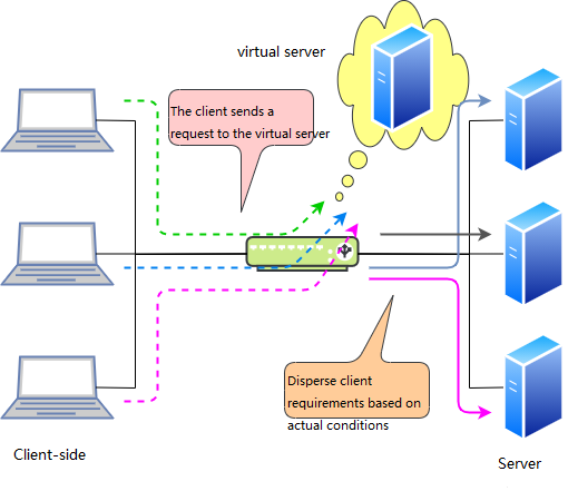
Virtual server
Load balancing equipment is not only suitable for servers, but also for security devices such as firewall and proxy server.
Load Balancing Algorithm Types
What is SSL Acceleration?
SSL acceleration is a function of dedicated load balancing equipment, and the internal device that performs this function is called SSL accelerator.
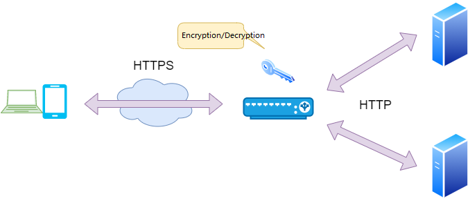
SSL Communication
Encrypting and decrypting the transmitted data during SSL communication with the server requires fairly complex calculations, which further increases the processing load on the server CPU. Compared to HTTP traffic that does not perform encryption and decryption, the processing load of HTTPS is 10 times that of HTTP. At this time, by using an SSL accelerator to decrypt the client’s HTTPS request and convert it into an HTTP request before forwarding it to the actual server, the processing load on the server CPU can be reduced. In this way, the overall system can not only improve the server response speed, but also reduce the number of servers, and can forward more Web service content per unit time.
How Many Types of Layer 3 Switches according to the Performance Classification?
According to the backplane capacity of the layer 3 switch, it can be divided into high-end switch, mid-range switch and low-end switch.
High-end Layer 3 Switches
The frame-type layer 3 switch is composed of routing engine, switching fabric, line card module, fan module and power supply module, and is generally used as the core switch of the enterprise in the data center.
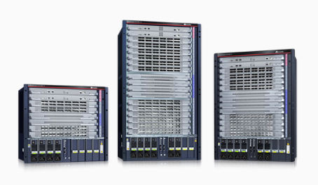
High-end Layer 3 Switches
In order to improve the reliability of the switch, all modules except the line card module provide redundant structure. Power or fan modules are typically 1+N or N+N redundant, and routing engines are typically 1+1 redundant. Layer 3 Switches generally form a three-layer redundancy structure with stacking multiple devices to improve the availability of the entire system.
Midrange Layer 3 Switches
Midrange layer 3 switches are generally box -type switches or frame-type switches with a maximum number of slots of 4, which are used for aggregation switching of enterprise core switches and access switches.
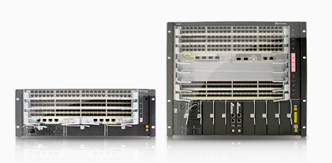
Midrange Layer 3 Switch
Low-end Layer 3 Switches
The low-end Layer 3 switch is generally a box -type switch or a desktop switch, which is used as an access switch for an enterprise, usually with 24 ports or 48 ports. Some act as access points for IP phones or wireless LANs and can also use power over Ethernet (PoE) directly.
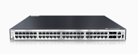
Low-end layer 3 switch
What are the Functions of Layer 3 Switches?
Although the functions provided by each manufacturer’s layer 3 switch are different, these functions are roughly divided into several categories: authentication, management, routing protocol, QoS, IP tunneling, VLAN, STP, and so on.
Functions of Layer 3 Switches
In a layer 3 switch, the function of group management is performed by the CPU software directly. User direct communication is processed by the ASIC (hardware) to achieve high-speed forwarding of packets.
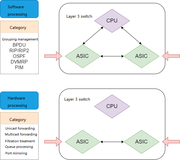
Functions of layer 3 switch
What is a VLAN?
A broadcast domain consisting of one or more hubs can be called a flat network. Interconnected terminals receive all broadcast frames from the network. As the number of connected terminals increases, so does the number of broadcasts, and the network situation becomes more mixed. In this case, it is necessary to use VLAN (Virtual Lan) technology to logically segment the entire flat network. A VLAN corresponds to a broadcast domain, and the broadcast domains of different VLANs are isolated from each other, so the scale of broadcast traffic within the broadcast domain can be controlled.
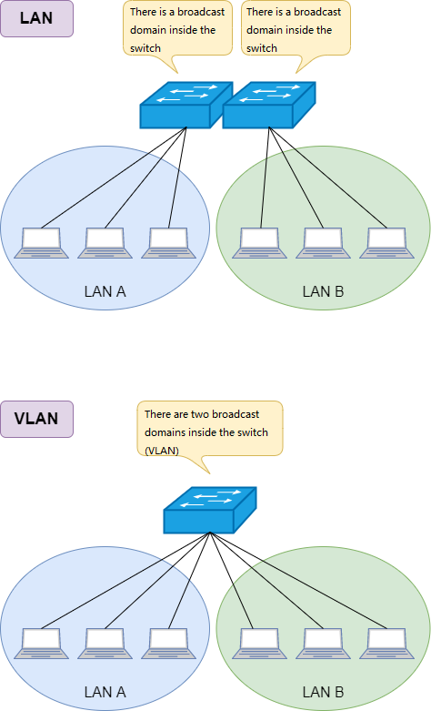
VLAN technology
The switch can easily modify the properties of the physical port through setting, so that the physical port can be added to a VLAN without changing the corresponding physical line. Communication between VLANs requires routing, and it is not possible to communicate with the endpoints of different VLANs without the help of routers or layer 3 switches, so security is also guaranteed.
What is a Port-based VLAN?
Port-based VLAN is to set the VLAN ID on the port of the switch, and multiple ports with the same VLAN ID form a VLAN. In the initial state of the switch, the default VLAN ID of all ports = 1 (that is, VLAN 1), and the VLAN ID of any port can be set. For example, if you modify a port to VLAN ID = 2, then this port belongs to VLAN 2.
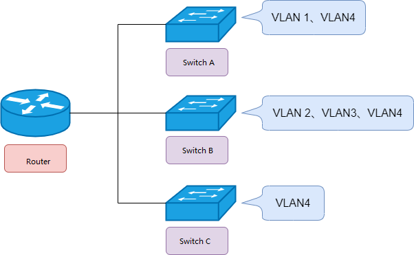
What is a Tag VLAN?
When a VLAN needs to span multiple switches, trunk port and tag VLAN will be used. The tag VLAN completes the receiving and sending of data frames through the trunk port, and the data frame needs to add 4 bytes of IEEE 802.1 Q to define header information (that is, VLAN tag information). The process of labeling data frames is called tagging. When tagging is complete, the maximum length of the data frame changes from 1518 bytes to 1522 bytes, with 12 bits of VLAN ID information, that is, the maximum number of supported VLANs is 4096.
Tag VLAN
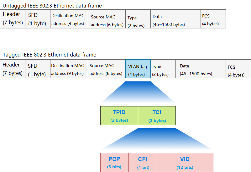
Untagged Ethernet Data Frame
In Ethernet, the value of TPID is 0x8100 in a data frame. If the value behind the source address is not 0x8100, then it is not TPID information, but identified as ” length/type”. When the value of Length/Type is below 0x05DC, it indicates the length of the data frame; The value above 0x0600 indicates the type of data frame. The data frame type values: IPv4 is 0x0800, ARP is 0x0806, IPv6 is 0x86DD, and so on.
A switch that does not support IEEE 802.1Q will treat 0x8100 as a data frame type because it does not recognize the TPID, but there is no data frame of 0x8100, and the switch will discard it as an error frame. IEEE 802.1Q also defines a field: TCI, which can be divided into 3 types: PCP, CFI and VID.
3 Types of TCI
What is a Native VLAN?
Native VLAN is for trunk ports. If the data frame is untagged before entering the trunk port, the trunk port will tag it with the native VLAN, and the data frame will be transmitted as the native VLAN. If the frame is tagged before entering the trunk, and the trunk port allows the VLAN ID to pass, the frame passes. VLAN data frames that are not allowed by the trunk port are abandoned. By default, the switch uses a VLAN with a VLAN ID of 1 as the native VLAN. Native VLANs are customizable and typically use a VLAN other than VLAN 1 as the native VLAN as the management VLAN.
What is a Trunk Port?
When using tag VLAN to pass the VLAN ID to other switches, first set the trunk port. The trunk port can belong to multiple VLANs and communicate with other switches for sending and receiving frames of multiple VLANs. The link between the trunk ports of two switches is called a trunk link.
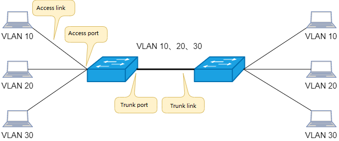
Trunk link
Access port and access link correspond to trunk port and trunk link. The access port belongs to only one VLAN, and the access link transmits only
one VLAN data frame.
What is a Private VLAN?
Private VLAN, also called PVLAN, refers to the function of constructing a layer of VLAN inside the VLAN, also called multi-layer VLAN.
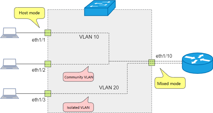
Private VLAN
PVLANs can further segment broadcast domains, reduce broadcast traffic within VLANs, and secure communications. Hotels, apartments and other places use this function to control the connection between the server or gateway and the terminal, so that different terminals cannot communicate with each other. PVLAN consists of primary VLAN and secondary VLAN, the secondary VLAN is associated with a primary VLAN.
What is the Difference between Static and Dynamic VLANs?
By inputting switch commands, a switch port is fixedly assigned to a certain VLAN. This VLAN division method is called Static VLAN. In contrast, the method of automatically assigning a certain VLAN according to the terminal or user information of connection port is called Dynamic VLAN.
Specifically, the switch determines which VLAN the port belongs to based on the MAC address of the endpoint or based on 802.1X authentication. In a dynamic VLAN, an endpoint acquires a fixed VLAN regardless of which switch it is connected to. MAC address -based authentication is possible through a database inside the switch, but in most cases dynamic VLANs are implemented using a RADIUS server.
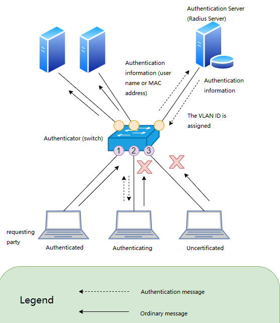
Dynamic VLAN
How do VLANs Interoperate?
Layer 2 Switches
After multiple VLANs are set on a layer 2 switch, data frames can only be forwarded within the same VLAN in a single switch and cannot be forwarded between different VLANs. When it is necessary to forward data between multiple VLANs, a trunk link is generally used to connect the router, through which routing is performed between VLANs.
Layer 3 Switches
Layer 3 switch can perform routing directly between VLANs inside the switch.
Related Products:
-
 QSFP28-100G-SR4 100G QSFP28 SR4 850nm 100m MTP/MPO MMF DDM Transceiver Module
$40.00
QSFP28-100G-SR4 100G QSFP28 SR4 850nm 100m MTP/MPO MMF DDM Transceiver Module
$40.00
-
 QSFP28-100G-IR4 100G QSFP28 IR4 1310nm (CWDM4) 2km LC SMF DDM Transceiver Module
$110.00
QSFP28-100G-IR4 100G QSFP28 IR4 1310nm (CWDM4) 2km LC SMF DDM Transceiver Module
$110.00
-
 QSFP28-100G-DR1 100G QSFP28 Single Lambda DR 1310nm 500m LC SMF with FEC DDM Optical Transceiver
$180.00
QSFP28-100G-DR1 100G QSFP28 Single Lambda DR 1310nm 500m LC SMF with FEC DDM Optical Transceiver
$180.00
-
 QSFP28-100G-FR1 100G QSFP28 Single Lambda FR 1310nm 2km LC SMF with FEC DDM Optical Transceiver
$215.00
QSFP28-100G-FR1 100G QSFP28 Single Lambda FR 1310nm 2km LC SMF with FEC DDM Optical Transceiver
$215.00
-
 QSFP28-100G-SR1.2 Single Rate 100G QSFP28 BIDI 850nm & 900nm 100m LC MMF DDM Optical Transceiver
$280.00
QSFP28-100G-SR1.2 Single Rate 100G QSFP28 BIDI 850nm & 900nm 100m LC MMF DDM Optical Transceiver
$280.00
-
 QSFP28-100G-LR4 100G QSFP28 LR4 1310nm (LAN WDM) 10km LC SMF DDM Transceiver Module
$285.00
QSFP28-100G-LR4 100G QSFP28 LR4 1310nm (LAN WDM) 10km LC SMF DDM Transceiver Module
$285.00
-
 QSFP-DD-400G-SR4.2 400Gb/s QSFP-DD SR4 BiDi PAM4 850nm/910nm 100m/150m OM4/OM5 MMF MPO-12 FEC Optical Transceiver Module
$900.00
QSFP-DD-400G-SR4.2 400Gb/s QSFP-DD SR4 BiDi PAM4 850nm/910nm 100m/150m OM4/OM5 MMF MPO-12 FEC Optical Transceiver Module
$900.00
-
 QSFP-DD-400G-DR4 400G QSFP-DD DR4 PAM4 1310nm 500m MTP/MPO SMF FEC Optical Transceiver Module
$400.00
QSFP-DD-400G-DR4 400G QSFP-DD DR4 PAM4 1310nm 500m MTP/MPO SMF FEC Optical Transceiver Module
$400.00
-
 QSFP-DD-400G-SR8 400G QSFP-DD SR8 PAM4 850nm 100m MTP/MPO OM3 FEC Optical Transceiver Module
$149.00
QSFP-DD-400G-SR8 400G QSFP-DD SR8 PAM4 850nm 100m MTP/MPO OM3 FEC Optical Transceiver Module
$149.00
-
 QSFP-DD-400G-FR4 400G QSFP-DD FR4 PAM4 CWDM4 2km LC SMF FEC Optical Transceiver Module
$500.00
QSFP-DD-400G-FR4 400G QSFP-DD FR4 PAM4 CWDM4 2km LC SMF FEC Optical Transceiver Module
$500.00
-
 QSFP-DD-400G-LR4 400G QSFP-DD LR4 PAM4 CWDM4 10km LC SMF FEC Optical Transceiver Module
$600.00
QSFP-DD-400G-LR4 400G QSFP-DD LR4 PAM4 CWDM4 10km LC SMF FEC Optical Transceiver Module
$600.00
-
 QSFP-DD-400G-LR8 400G QSFP-DD LR8 PAM4 LWDM8 10km LC SMF FEC Optical Transceiver Module
$2500.00
QSFP-DD-400G-LR8 400G QSFP-DD LR8 PAM4 LWDM8 10km LC SMF FEC Optical Transceiver Module
$2500.00