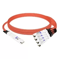
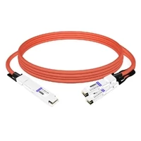
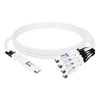
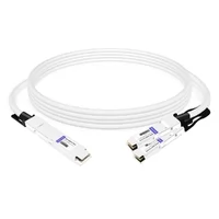
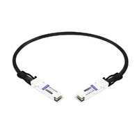
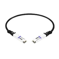
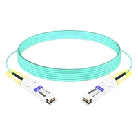
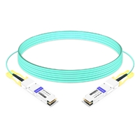
A 400G QSFP112 port looks straightforward: four high-speed electrical lanes combine to deliver one 400G interface. Breakout seems equally simple—divide those lanes into two 200G links or four 100G links.
In practice, however, the cable is only one part of the design.
A successful QSFP112 breakout depends on the switch or NIC ASIC, firmware, port-group architecture, electrical lane mode, module or cable capabilities, optical PMD, far-end interfaces, and FEC configuration. A mismatch at any one of these layers can prevent the link from coming up.
This guide explains how QSFP112 breakout works, how 2x200G differs from 4x100G, when passive breakout is possible, when a gearbox or active cable is required, how parallel optics such as DR4 can be broken out, and what to verify before deployment.
If you need the fundamentals first, see the complete QSFP112 400G guide for form factor, signaling, optical types, and applications.
Quick Answer: Does QSFP112 Support Breakout?
Yes—when the host platform supports it.
A 400G QSFP112 electrical interface normally uses four high-speed PAM4 lanes. A compatible platform can allocate those lanes as:
- 1x400G: four lanes for one logical interface
- 2x200G: two lanes per logical interface
- 4x100G: one lane per logical interface
At approximately 106.25 Gb/s per electrical lane, or 53.125 GBd PAM4, these mappings correspond to the 100G-per-lane electrical architecture used by interfaces such as 400GAUI-4, 200GAUI-2, and 100GAUI-1.
But the physical QSFP112 connector alone does not guarantee breakout support. IEEE defines 400GAUI-4 as a four-lane 100G-per-lane electrical interface, while 200GAUI-2 uses two such lanes.
Before selecting a breakout cable, verify the following:
- The host ASIC supports the target logical-port mode.
- The exact switch, NIC, or DPU supports that breakout mode.
- The firmware or NOS release supports the configuration.
- The port group has enough logical-port resources.
- The cable or transceiver supports the required host and media lane mapping.
- The far-end interfaces use compatible electrical or optical signaling.
- FEC and link settings are compatible at both ends.
The most important rule is simple:
A breakout cable carries or converts interfaces that the platform supports; it does not create unsupported logical ports.
What a QSFP112 Breakout Actually Does
A QSFP112 port carries 400G as four electrical lanes, each running roughly 106.25 Gb/s of PAM4. In normal mode those four lanes bond into one 400G link over a 400GAUI-4 host interface. In breakout mode the switch stops bonding them. Each lane, or each pair of lanes, becomes its own logical port with its own link state.
Two shapes exist:
| Mode | Lanes per link | Far-end endpoint | Aggregate |
| 2x200G | 2 x 100G PAM4 | QSFP56 200G | 400G |
| 4x100G | 1 x 100G PAM4 | QSFP28-class 100G | 400G |
This describes the host-side electrical mapping.
The optical side can be different because an optical transceiver may contain DSP or gearbox circuitry between its host electrical interface and its optical lanes.
That distinction is essential when evaluating QSFP112 breakout.
For example, a 400G DR4 optic has four independent 100G optical lanes. Those lanes can be optically faned out to four 100G DR1 endpoints. A conventional 100G QSFP28 DR1 module can still present 4x25G NRZ to its local switch while internally converting that electrical interface to a single 100G-PAM4 optical lane.
Therefore:
Electrical lane breakout and optical lane breakout are related, but they are not always the same thing.
QSFP112 Breakout: 2x200G vs 4x100G
QSFP112 Breakout Modes Compared
| Feature | 2x200G | 4x100G |
| Native 100G/lane host mapping | 2 lanes per 200G link | 1 lane per 100G link |
| Number of logical links | 2 | 4 |
| Native electrical interface | 200GAUI-2-class | 100GAUI-1-class |
| Parallel optical example | 2x200G DR2/VR2 | 4x100G DR1/VR1 |
| Legacy electrical endpoint issue | QSFP56 commonly uses 4x50G PAM4 | QSFP28 commonly uses 4x25G NRZ |
| Passive electrical breakout | Only when lane rates/counts match | Only when lane rates/counts match |
| Active conversion may be required | Yes | Yes |
| Typical use | 200G servers, NICs, DPUs | 100G endpoints and migration |
Why the Endpoint Interface Matters
A common mistake is to compare only aggregate speeds.
For example:
- 400G QSFP112 = 4x100G-class electrical lanes
- Traditional 200G QSFP56 = typically 4x50G PAM4 electrical lanes
- Traditional 100G QSFP28 = typically 4x25G NRZ electrical lanes
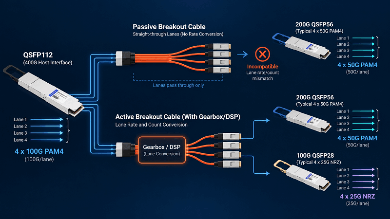
A passive copper cable cannot convert:
2x100G PAM4 → 4x50G PAM4
or
1x100G PAM4 → 4x25G NRZ
It has no gearbox or DSP capable of changing the lane count or electrical modulation rate.
NVIDIA similarly notes that its 100G-PAM4 cables and transceivers cannot simply downshift to legacy 50G-PAM4 or 25G-NRZ signaling; special active cable solutions are used where those signaling domains must be connected.
This means a direct QSFP112-to-QSFP56 or QSFP112-to-QSFP28 breakout must be evaluated based on the actual electrical interface—not just the form factor and Ethernet speed.
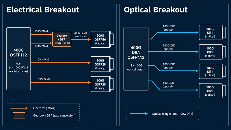
Optical Breakout Is Different
Optical modules can solve the problem differently.
Consider 400GBASE-DR4.
The 400G module transmits four independent 100G-PAM4 optical lanes over four fiber pairs. Those optical lanes can be separated into:
- four 100G DR1 links, or
- two 200G DR2 links,
provided the transceivers and host platforms support the configuration.
Cisco documents exactly these breakout applications for its QSFP112 400G DR4 module: up to four 100G DR1 or two 200G DR2 links. The same principle applies to its VR4 implementation for compatible short-reach links.
This works even when the far-end module’s host electrical interface is different, because the far-end optical module can contain the required gearbox.
The practical lesson is:
Do not use the electrical interface of the far-end switch port alone to determine whether an optical breakout is possible. Check both the optical PMD and the transceiver’s internal electrical-to-optical mapping.
2x200G Breakout Is Not Automatically “Easier”
It is tempting to assume that 2x200G is always easier than 4x100G because both QSFP112 and QSFP56 use PAM4.
That assumption is incomplete.
A native 2x200G breakout from a 400G QSFP112 host uses two 100G-class electrical lanes for each 200G logical interface. A traditional 200G QSFP56 interface commonly uses four 50G-PAM4 electrical lanes.
Those interfaces have the same Ethernet capacity, but they do not have the same electrical lane architecture.
Therefore, a passive QSFP112-to-2xQSFP56 copper cable is possible only if the specific host and cable architecture provides compatible lane signaling. Otherwise, a gearbox-capable active cable, module, or platform is required.
A redriver alone does not perform this conversion. Redrivers compensate for electrical loss and improve signal integrity; they do not change a 2-lane 100G-per-lane interface into a 4-lane 50G-per-lane interface.
Power Savings in 2x200G Optical Operation
There can still be a genuine power advantage when a 400G optical module supports a reduced-lane 200G operating mode.
For example, NVIDIA’s MMA1Z00-NS400 400G QSFP112 SR4 transceiver specifies:
- 8.5 W maximum at 400G
- 5.5 W maximum at 200G
The 200G mode activates two channels rather than all four.
That is a maximum-power reduction of approximately 35%.
At scale, reduced-lane optical operation can therefore lower transceiver power and cooling demand. However, the exact saving is module-specific and should not be assumed for every QSFP112 transceiver.
QSFP112 Breakout Is Primarily a Platform Capability
The Port-Group Rule
Breakout is not controlled only by the physical port being configured.
High-density switches often organize front-panel ports into ASIC port groups, SerDes groups, or logical-port pools. Changing the lane allocation on one physical interface can therefore affect neighboring interfaces.
The exact behavior is platform-specific.
For example, Cisco documents a Nexus C9364C-H1 architecture in which breakout is permitted only on the first interface of each four-port group. When that interface is broken out, the three adjacent front-panel ports in the same group are removed from configuration and verification commands.
That is a property of that particular platform—not a universal NX-OS rule.
Other Cisco platforms use different port-group restrictions. Some require odd-numbered ports, some pair adjacent ports, and some allow per-port breakout without removing three neighboring interfaces.
Therefore, never design a rack around a generic statement such as:
“Every 400G port can become four 100G ports.”
Instead, check the hardware port map for the exact SKU and software release.
Examples of Platform-Specific Support
| Platform | Relevant Capability | Important Note |
| Cisco Nexus 3432D-S | 400G to 2x200G and 4x100G | Uses platform-specific NX-OS breakout mappings |
| H3C S9827-128DH | 400G QSFP112; documented 2x200G and 4x100G modes | Some operating modes and grouped ports depend on software release |
| NVIDIA ConnectX-7 / BlueField-3 QSFP112 | Supports QSFP112 and backward-compatible QSFP form factors | Electrical downshift and breakout behavior depends on cable/module type |
| Arista platforms | Wide range of logical-port breakout modes | Exact SerDes and DLP allocation varies by switch family |
Cisco documents 200g-2x and 100g-4x breakout mappings for supported 400G Nexus platforms.
H3C documents both 2x200GE and 4x100GE split modes on the S9827-128DH, which uses QSFP112 interfaces, while also documenting software and interface-group restrictions.
The conclusion is not that one vendor implements breakout better than another. It is that breakout capability belongs to a specific combination of ASIC, port design, SKU, firmware, and interface type.
Selecting the Cable for QSFP112 Breakout
The Reach/Power/Cost Ladder
| Cable | Reach | Power | Best use |
| Passive DAC breakout | 1-3 m | ~0 W per end | Same-rack switch to NIC |
| Active DAC / ACC breakout | 3-5 m | 0.5-1 W | Adjacent racks |
| AEC breakout | 3-5 m | 1-2 W | AI rack-to-rack, low latency |
| AOC breakout | 1-30 m (to 100 m) | 2-3 W per end | Inter-rack, flexible routing |
Start at the top and move down only when reach forces you. Copper is cheaper and lower-power until distance rules it out. Enable link training at bring-up if you’re running passive DACs or long fiber runs.
Already know your split mode? Match reach to your rack layout, then look at 400G breakout AOC cables for the optical path.
Optical Breakout Cabling Types
Two harness families cover most deployments. An MPO-12 to 2x breakout (splitter or Y-cable) serves the 2x200G path. An MPO-12 to 4x duplex LC harness serves the 4x100G parallel path.
A four-channel 400G QSFP112 optic uses a single MPO-12/APC connector with only 8 of 12 fibers active: four transmit, four receive. The other four fibers sit dark. For the harness side, FiberMall’s MPO to LC breakout cable is built for exactly this fan-out.
Which Optic Can Break Out at All
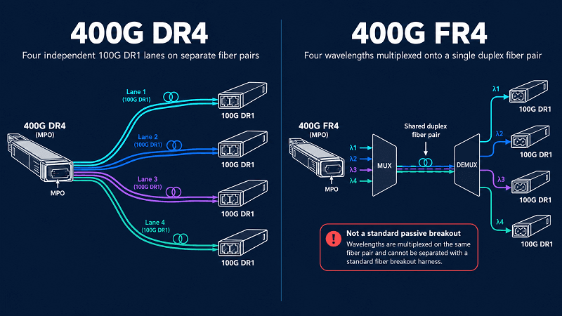
Parallel optics break out. WDM optics don’t.
SR4, VR4, and DR4 are parallel. They dedicate separate fiber pairs per lane, so the lanes can fan to separate endpoints. Documented split forms include 400GBASE-DR4 into 4x100GBASE-DR or 2x200GBASE-DR4 at 500 m, and 400GBASE-FR4 into 4x100GBASE-FR1 or 2x200GBASE-FR4 at 2 km.
FR4 and LR4 are not. They multiplex four wavelengths onto shared fiber, and those wavelengths can’t be routed to different endpoints. If breakout is part of your plan, the QSFP112 module types table shows which variants are parallel and which are WDM.
CMIS Selection: How the Module Declares the Breakout
For a QSFP112 breakout, the host selects the active application through the CMIS Application Select (APSEL) register. The module’s Application Descriptors, stored in EEPROM Page 0x00 at bytes 0x56 through 0x75, list exactly which breakout modes that module supports. The media lane count byte reveals the shape: 0x44 for four host lanes, 0x88 for eight. Wave2Wave’s CMIS programming and breakout configuration guide documents the full programming model.
Why does this matter before you order? A QSFP112 breakout only works if the module advertises it. Vendor implementation varies. Some vendors program only APP 1 and APP 2, and newer firmware may add breakout applications later. DSP capability matters too, since some breakout modes need per-lane DSP that not every chip provides.
Reading the descriptor list takes about five minutes and prevents an expensive wrong purchase.
Installing a QSFP112 Breakout: Polish, Pins, and Polarity
Use APC, Not UPC
100G-PAM4 optics are sensitive to back reflections, so they require angled (APC) polish. MPO-12/APC is green. MPO-12/UPC is blue, and it’s what you’ll find on most older 40G and 100G builds.
The two don’t mix. An APC connector won’t seat correctly against a UPC one, and if it somehow does, the reflection penalty degrades or kills the link.
Watch Pins and Holes
Transceivers carry alignment pins. MPO-12/APC harness connectors carry alignment holes. Forcing a pinned connector into a transceiver damages both ends. The white dot on the connector marks the pin-1 side, and that is your orientation reference.
Mind Polarity
With Type-A parallel fiber trunks, include at least one Type-B crossover segment in the link so the lanes land correctly. A single crossed or swapped channel presents exactly like a bad optic, which is the theme of the diagnostics section below. Map and label every leg before powering up. The MPO-12 connector guide covers APC versus UPC, polarity, and pin orientation in one place.
Configuring Breakout on Cisco and Arista
QSFP112 breakout configuration differs by vendor, and the two dominant platforms think about it in different ways.
Cisco NX-OS uses an interface-level breakout command:
interface breakout module 1 port 1 map 25g-4x
Mappings include 10g-4x, 25g-4x, and 50g-2x. Remember the port-group rule here: breakout only fires on the first port of a front-port group.
Arista EOS treats multi-lane ports differently. You set the rate with the speed command on the primary lane, and EOS allocates Dynamic Logical Ports (DLP) on its own. Port naming follows Ethernet port#/lane#. Use show hardware port-group to see group state, and service interface inactive expose to reveal interfaces that are present but inactive (Arista EOS User Manual).
Then verify per channel, not per port. A breakout can be half-working with three of four legs live, and a single “port up” reading tells you nothing about the others. The 400G optical module overview covers the module-side checks that pair with this.
FEC and Breakout Faults: What Goes Wrong
On a QSFP112 breakout, each channel carries 100G per lane, so RS(544,514) KP4 FEC is required there. Both ends of each channel must use the same mode. Mismatch one leg and that leg flaps on its own. Enable link training during initial bring-up, especially with passive DACs or long fiber runs.
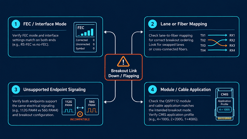
Three failures look identical from the console:
1. A FEC mode mismatch on one leg.
2. A physical channel swap in the harness, where lanes land on the wrong leg.
3. An endpoint that doesn’t support the split rate.
An integrator named Dev brought up a 4x100G breakout and watched three legs report up while one flapped. His first move was to change the FEC setting on the bad leg. Nothing changed. He swapped the optic. Still flapping.
Only when he traced the harness fiber by fiber did he find two channels crossed at the patch panel. The near-end lane 3 was landing on a far-end lane expecting different framing. The “FEC problem” was a patching problem in a FEC costume.
The isolation method that works: force speed and FEC on a single channel, test it, then test the other leg. If one leg is clean and the other flaps, your problem is patching or endpoints, not FEC policy. This section covers breakout-caused faults only. A wider diagnostics playbook for DOM/DDM triage and optics cleaning is coming later in this cluster, and we’ll cross-link it when it publishes.
Pre-Deployment QSFP112 Breakout Checklist
Work through this in order. Each step assumes the one above it passed.
1. Confirm the switch ASIC supports 112G PAM4 and multiple logical ports.
2. Confirm the target split appears in the platform’s port guide for your firmware and SKU.
3. Confirm the port group allows the split, and that losing the adjacent ports is acceptable.
4. Confirm the module’s application descriptors advertise the breakout mode.
5. Confirm the optic type can break out: parallel SR4/VR4/DR4, not WDM FR4/LR4.
6. Confirm the far-end endpoints run the split rate.
7. Confirm APC polish and correct polarity/pin orientation, then map every leg.
8. Confirm FEC mode matches on every channel, then verify each channel independently.
Steps 1 through 3 have nothing to do with the cable, which is the whole point. Most failed breakout projects fail there.
FAQ
Does QSFP112 support breakout?
On platforms that allow it, yes. You get two 200G links or four 100G links from one 400G port.
What is the difference between 2x200G and 4x100G breakout?
2x200G pairs two lanes per link and runs PAM4 at both ends, so no modulation conversion is needed. 4x100G puts one lane per link and usually hits 25G NRZ endpoints, which needs compatible host modes, active conversion, or single-lambda-100G optics.
Can a passive QSFP112 breakout cable convert 400G into 4x100G?
No. A passive cable can’t convert 100G PAM4 into 25G NRZ. If your far end is a legacy QSFP28 port, choose a different split or different endpoints.
Can QSFP112 FR4 modules be used for breakout?
No. FR4 and LR4 multiplex four wavelengths onto shared fiber, and those wavelengths can’t be routed to separate endpoints. Only parallel optics break out.
Why did my QSFP112 breakout disable three other ports?
You hit the port-group rule. On Cisco NX-OS, breakout works only on the first port of a front-port quad group, and the three adjacent ports are removed while the breakout is active.
Do I need to configure the switch for QSFP112 breakout?
Yes. The switch must create the logical ports first. The cable only carries lanes the platform has already split.
How many fibers does a QSFP112 breakout use?
Eight of the twelve in an MPO-12: four transmit and four receive.
Can I break out a QSFP112 port to QSFP28 transceivers?
It depends on the host modes available at both ends. The electrical mismatch between 100G PAM4 and 25G NRZ is the gate, so verify it before you buy.
Conclusion
A QSFP112 breakout is a platform decision, and it resolves in a fixed order: ASIC, port guide, port group, application descriptor, endpoint, cable, FEC. Engineers who reverse that order end up with a shelf of cables that can’t fix a closed gate.
Two rules carry most of the weight. 2x200G is the easier and lower-power split, with PAM4 at both ends and a documented drop from 8.5 W to 6.5 W per module. Parallel optics break out and WDM optics don’t, so SR4, VR4, and DR4 are your candidates while FR4 and LR4 are not.
If you’re planning a breakout deployment, FiberMall’s cabling range covers the copper and optical paths. The 800G OSFP to 2xQSFP112 AEC handles the AI-spine fanout case.
For direct connections, the QSFP112 AOC cables and matching DAC/ACC range fit the 400G QSFP112 cage. For a QSFP112 breakout to QSFP56, which depends on your switch platform and firmware, request a breakout configuration review and we’ll match the split to your hardware.
Need the broader picture first? The complete QSFP breakout cable guide covers the generic 40G-to-800G options, and the QSFP-DD breakout cable guide covers the 8-lane sibling case.
Related Products:
-
 OSFP8-4QSFP112-AC4M 4m (13ft) 800G Twin-port OSFP to 4x200G QSFP112 InfiniBand NDR Breakout Active Copper Cable
$900.00
OSFP8-4QSFP112-AC4M 4m (13ft) 800G Twin-port OSFP to 4x200G QSFP112 InfiniBand NDR Breakout Active Copper Cable
$900.00
-
OSFP8-2QSFP112-AC4M 4m (13ft) 800G Twin-port OSFP to 2x400G QSFP112 InfiniBand NDR Breakout Active Copper Cable
$800.00
-
OSFP8-4QSFP112-PC1M 1m (3ft) 800G InfiniBand NDR Twin-port OSFP to 4x200G QSFP112 Passive Breakout Direct Attach Copper Cable
$165.00
-
OSFP8-2QSFP112-PC1M 1m (3ft) 800G InfiniBand NDR Twin-port OSFP to 2x400G QSFP112 Passive Breakout Direct Attach Copper Cable
$165.00
-
QSFP112-400G-AC2M 2m (7ft) 400G QSFP112 to QSFP112 Active Direct Attach Copper Cable
$209.00
-
QSFP112-400G-PC50CM 50cm (1.6ft) 400G QSFP112 to QSFP112 Passive Copper Cable
$115.00
-
QSFP112-400G-AOC-10M 60m (197ft) 400G QSFP112 to QSFP112 Active Optical Cable
$1769.00
-
QSFP112-400G-AOC-10M 10m (33ft) 400G QSFP112 to QSFP112 Active Optical Cable
$1669.00
-
QSFP112-400G-AOC-3M 3m (10ft) 400G QSFP112 to QSFP112 Active Optical Cable
$1643.00
-
QSFP112-400G-AOC-1M 1m (3ft) 400G QSFP112 to QSFP112 Active Optical Cable
$1637.00