As a network engineer, designing a network will involve switch selection. What should we pay attention to when selecting switches?
Key points for switch selection:
(1) Standard (fixed-configuration switch /modular switch)
(2) Function (Layer 2 switch/Layer 3 switch)
(3) Number of ports
(4) Port bandwidth
(5) Exchange capacity
(6) Packet forwarding rate
Standard of switch:
Switches are mainly classified into fixed-configuration and modular switch.
Sample diagram of a fixed-configuration switch

Sample diagram of a modular switch
-
Fixed-configuration switch
(1) Fixed-configuration switch can be understood as an iron box. Generally, fixed-configuration switch has fixed number of ports, fixed power modules, fans, etc.; Therefore, fixed-configuration switch is typically not expandable.
(2) Fixed-configuration switch supports stacking technology to improve scalability, so we can form multiple fixed-configuration switch into one switch.
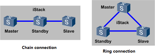
Chain connection and ring connection
3) Under normal circumstances, fixed-configuration switch is used in a network access layer or aggregation layer.
-
Modular switch
A modular switch is based on a chassis, and interface boards, switch boards, and power modules can be configured independently according to requirements. The scalability of a frame switch is generally based on the number of slots. Modular switches are generally used in the core position of network.
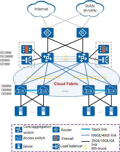
Networking diagram
As shown in the network diagram above: In the data center network, CE5800, CE6800, and CE8800 are box-type devices, which are generally used as the access layer; The CE128 is a frame-type device and is generally used as the core layer.
Therefore, when selecting a device, you can determine whether to choose fixed-configuration switch or a modular switch based on the actual use level of the switch.
Function
Switches are classified according to the working protocol layer: they can be divided into Layer 2 switches and Layer 3 switches.
Differences between Layer 2 switches and Layer 3 switches:
Layer 2 Switch:
Main functions of the switches that work on the second layer of the data link layer of the OSI reference model, include physical addressing, error checking, frame sequence and flow control. (As shown in the figure below, the Layer 2 switch works at the data link layer and can process data frames)
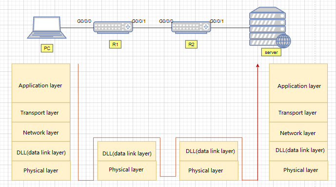
Layer 2 switch
Layer 3 Switch:
A device with three-layer switching function, is a second-layer switch with third-layer routing function, which is an organic combination of the two, not simply superimposing the hardware and software of the router device on the LAN switch. (As shown in the figure below, the three-layer switch works at the network layer and can process data packets)
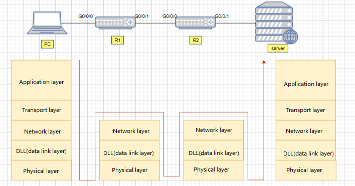
Layer 3 switch
Number of ports
Fixed-configuration switch
The number of ports that a switch can provide is basically fixed for each type of fixed-configuration switch, generally 24 or 48 access ports and 2-4 uplink ports. Take Huawei CE5850-48T4S2Q-EIas an example (as shown below). There are 48 1000M access ports, 4 10G uplink ports, and 2 40G uplink ports;
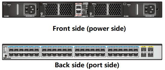
Sample diagram of a fixed-configuration switch
Modular switch
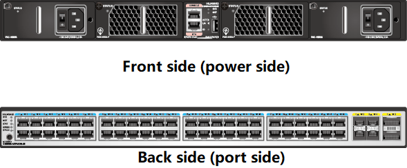
The number of ports of modular switches are related to the number of boards configured, which is generally the maximum number of ports that each chassis can support when the interface board with the highest density is configured. Take Huawei’s CE12804 as an example, which supports 4 service board LPUs, and the ports are related to the specific board model. For a 36-port 100G board, there are a total of 144 100G ports when the board is fully inserted.
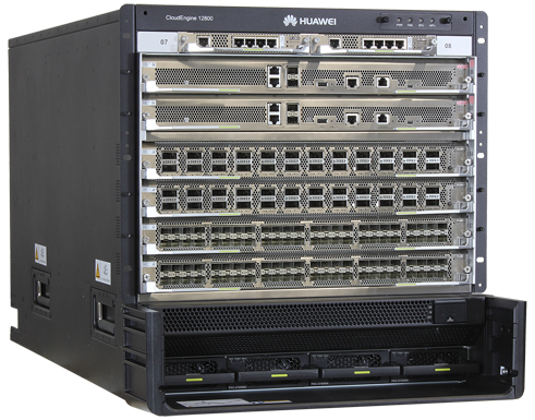
Sample diagram of a modular switch
How to choose a switch based on the number of ports:
When selecting a switch, it needs to be based on the current business situation and future scalability. The number of switch ports represents the number of terminals you need to access.
For a switch with 48 access ports, if one terminal occupies one port, then one switch can connect to 48 terminals. Five such switches are needed in a company with 200 employees.
Port Speed
The port speeds that switch supports:
The port speeds provided by the current switch include100Mbps/1000Mbps/10Gbps/25Gbps and so on.
Port speed unit of the switch:
The port speed unit of the switch is bps (bit per second).

Switch port
Exchange Capacity
Switching capacity of switch
Switching capacity of switch is also known as backplane bandwidth or switching bandwidth.
Switching capacity is the maximum amount of data that can be handled between the switch interface processor (or interface card) and the data bus.
The backplane bandwidth marks the total data exchange capacity of the switch , and the unit is Gbit/s. The higher the switching capacity of a switch, the stronger the ability to process data, but at the same time the higher the design cost. Twice the capacity of all ports multiplied the number of ports should be less than the switching capacity, so as to realize full-duplex non-blocking switching.
The switching capacity is related to the standard of the switch.
For bus switches, switching capacity refers to the bandwidth of the backplane bus.
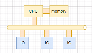
Bus switch
For a switch with switch matrix, the switching capacity refers to the total interface bandwidth of the switch matrix.
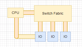
A switch with switch matrix
This switching capacity is a theoretical calculation value, but it represents the maximum possible switching capacity of the switch. The current switch design ensures that this parameter will not become the bottleneck of the entire switch.
Packet forwarding rate
Packet forwarding rate of switch:
Packet forwarding rate, also known as interface throughput, refers to the data packet forwarding capability on an interface of a communication device, and the unit is usually pps (packet per second). The packet forwarding rate of the switch is generally the result of actual measurement, which represents the actual forwarding performance of the switch.
Calculation method of packet forwarding rate:
The measurement standard of the packet forwarding rate is based on the number of 64-byte data packets (minimum packets) sent per unit time.
When calculating the packet forwarding rate, the fixed overhead of preamble and frame gap needs to be considered.
By default, the interframe gap is a maximum of 12 bytes, and users are advised to use the default configuration. If the user modifies the frame gap of the interface to a smaller value, the receiving end may not have enough time to receive the next frame after receiving a data frame, resulting in the inability to process forwarded packets in time and packet loss.
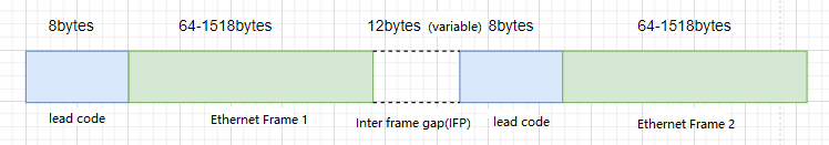
The interframe gap by default
We know that the length of the Ethernet frame is variable, but the processing power used by the switch to process each Ethernet frame has nothing to do with the length of the Ethernet frame. Therefore, when the interface bandwidth of the switch is constant, the shorter the Ethernet frame length, the more frames the switch needs to process, and the more processing power it needs to consume.
Supplementary points
When to Use Multiple Routing Protocols?
Multiple routing protocols are used when two different routing protocols need to exchange routing information. Of course, route redistribution can also exchange routing information. The following situations do not need to use multi-routing protocols:
- Upgrade from the old version of the Interior Gateway Protocol (IGP) to the new version of the IGP.
- You want to use another routing protocol but must keep the original one.
- You want to terminate internal routes, so they don’t get interfered by other routers that don’t have strict filtering policing.
- You are in an environment composed of routers from multiple manufacturers.
What is a Distance Vector Routing Protocol?
Distance vector routing protocols are designed for small network environments. In a large-scale network environment, such protocols will generate large traffic and occupy too much bandwidth when learning routes and maintaining routes.
If it does not receive a routing table update from the adjacent site within 90 seconds, it considers the adjacent site unreachable. The distance vector routing protocol will send the entire routing table to the adjacent site every 30 seconds, so that the routing table of the adjacent site can be updated.
In this way, it can collect a list of networks from other sites (directly connected or otherwise) for routing purposes. Distance vector routing protocols use hop count as a metric to calculate the number of routers it takes to reach a destination.
For example, RIP uses the Bellman-Ford algorithm to determine the shortest path, that is, the route that takes the fewest number of hops to reach the destination. The maximum number of hops allowed is usually set at 15. Terminals that must pass through more than 15 routers are considered unreachable.
There are several distance vector routing protocols: IP RIP, IPX RIP, Apple Talk RTMP, and IGRP.
What is a Link State Routing Protocol?
Link-state routing protocols are more suitable for large networks, but due to its complexity, routers require more CPU resources. It can discover broken links or newly connected routers in a shorter time, making the convergence time of the protocol shorter than that of distance vector routing protocols.
Usually, if it does not receive a HELLO message from an adjacent station within 10 seconds, it considers that the station is unreachable. A link-state router sends update messages to its neighbors, notifying it of all links it knows about.
It determines that the metric value of the optimal path is a numerical cost, whose value is generally determined by the bandwidth of the link. The link with the least cost is considered optimal. In the shortest path first algorithm, the value of the maximum possible cost can be almost infinite.
If there is no change in the network, the router only needs to periodically refresh the routing table that is not updated (the length of the period can be from 30 minutes to 2 hours).
There are several link state routing protocols: IP OSPF, IPX NLSP, and IS-IS.
Can a router use both a distance vector routing protocol and a link state routing protocol?
Yes. Each interface can be configured to use a different routing protocol; But they must be able to exchange routing information by redistributing routes.
What is an access table?
The access table is a series of rules added by the administrator to control the input and output of data packets in the router. It is not generated by the router itself. Access tables can allow or disallow packets to enter or exit to a destination.
The entries of the access table are executed sequentially, that is, when the data packet arrives, the entries first check whether it is bound by the first entry, if not, then execute it sequentially; If the packet matches the first entry, no matter it is allowed or forbidden, there is no need to perform the check of the following entries.
There can only be one access list for each protocol of each interface.
What types of access tables are supported?
An access list can be identified by its number. The specific protocols and their corresponding access table numbers are as follows:
- IP standard access list number: 1~99
- IP extended access list number: 100~199
- IP X Standard Access List Number: 800~899
- IP X extended access list number: 1000~1099
- AppleTalk access list number: 600~699
How to create IP standard access table?
An IP standard access list can be created by the following command: Access-list access list number {permit | deny} source [source-mask]
In this command:
- access list number: Determine which access list this entry belongs to. The numbers range from 1 to 99.
- permit | deny: Indicates whether this entry allows or blocks traffic from a specific address.
- source: Determine the source IP address.
- source – mask: Determines which bits in the address are used for matching. If a bit is “1”, it means that the bit in the address can be ignored, and if it is “0”, it means that the bit in the address will be used for matching. Wildcards can be used.
The following is an example of an access table in a router configuration file:
Router# show access-lists
Standard IP access list 1
deny 204.59.144.0, wildcard bits 0.0.0.255
ermit any
When to use route redistribution?
Route redistribution is usually configured on routers that are responsible for learning routes from one autonomous system and broadcasting them to another autonomous system. If you are using IGRP or EIGRP, route redistribution is usually performed automatically.
What is administrative distance?
Administrative distance refers to the routing trustworthiness of a routing protocol. Each routing protocol is assigned a trust level in descending order of reliability, and this trust level is called administrative distance. For routing information from two different routing protocols to a destination, the router first decides which protocol to trust based on the administrative distance.
How to configure redistribution?
Before routing can be redistributed, you must first:
1) Decide where to add new protocols.
2) Identify the Autonomous System Boundary Router (ASBR).
3) Decide which protocol is at the core and which is at the edge.
4) Decide on the direction of routing redistribution.
Routing updates can be redistributed using the following command (this example is for OSPF):
router(config-router) #redistribute protocol [process-id] [metric metric – value] [metric-type type – value] [subnets]
In this command:
- protocol: Indicates the source routing protocol for the router to redistribute routes.
The main values are: bgp, eqp, igrp, isis, ospf, static [ip], connected and rip.
- process-id: Specifies the OSPF process ID.
- metric: an optional parameter used to indicate the metric value of the redistributed route. The default metric value is 0.
Why is it important to identify adjacent routers?
It is not difficult to determine adjacent routers in a small network, because when a router fails, other routers can converge within an acceptable time.
But in a large network, the latency to discover a failed router can be significant. Knowing neighboring routers can speed up convergence because routers can learn about failed routers sooner and the interval between hello messages is shorter than the interval between routers exchanging information.
The router using the distance vector routing protocol can only find that the adjacent router is unreachable when the adjacent router does not send routing update information, and this time is generally 10 to 90 seconds, while a router using a link state routing protocol can find that the adjacent router is unreachable without receiving the hello message, and the interval is generally 10 seconds.
How do distance vector routing protocols and link state routing protocols discover adjacent routers?
A router using a distance vector routing protocol will create a routing table (including the networks directly connected to it), and it will send this routing table to the routers directly connected to it.
The adjacent router merges the received routing table into its own routing table, and it also sends its own routing table to its adjacent router. Routers using link-state routing protocols need to create a link-state table, which includes a list of destinations throughout the network.
In an update message, each router sends its entire list. When the adjacent router receives the update message, it copies the contents and sends the information to its neighbors. There’s no need to recalculate when forwarding routing table contents.
Note that routers using IGRP and EIGRP broadcast hello messages to discover neighbors and exchange routing updates like OSPF.
EIGRP maintains a neighbor table for each network layer protocol, which includes the address of the neighbor, the number of messages waiting to be sent in the queue, the average time required to receive message from or send to the neighbor, and the time that no message is received from a neighbor before the link is determined to be down.
What is an autonomous system?
An autonomous system is a group of routers and networks under the control of an administrative authority. It can be a router directly connected to a LAN and also connected to the Internet; It can be multiple LANs interconnected by an enterprise backbone.
All routers in an autonomous system must be interconnected, run the same routing protocol, and be assigned the same autonomous system number. Links between autonomous systems use external routing protocols such as BGP.
What is BGP?
BGP (Border Gateway Protocol) is a routing protocol that dynamically exchanges routing information between autonomous systems. The classic definition of an autonomous system is a group of routers under the control of an administrative organization that forwards messages to other autonomous systems using IGP and common metrics.
Using the term autonomous system in BGP is to emphasize the fact that the management of an autonomous system is to provide a unified internal routing plan for other autonomous systems, which provides a consistent routing plan for the networks reachable through it.
What types of sessions does BGP support?
Sessions between BGP neighboring routers are based on the TCP protocol. The TCP protocol provides a reliable transport mechanism that supports two types of sessions:
- External BGP (EBGP): a session between routers belonging to two different autonomous systems. These routers are contiguous and share the same medium and subnet.
- Internal BGP (IBGP): a session between routers within an autonomous system. It is used to coordinate and synchronize the process of finding routes within an autonomous system. BGP routers can be located anywhere in the autonomous system, with even several routers in the middle.
Note that the content of the initial data stream is the entire BGP routing table. But when the routing table changes later, the router only transmits the changed part. BGP does not need to periodically update the entire routing table. Therefore, a BGP sender must maintain the entire BGP routing table shared by all current peer routers during the time the connection is established.
BGP routers periodically send Keep Alive messages to confirm that the connection is alive. When an error or special situation occurs, the router sends a Notification message. When a connection fails, a notification message is generated, and the connection is disconnected. – From RFC11654, BGP operation.
Does BGP allow route redistribution?
Allow. Because BGP is mainly used for routing between autonomous systems, it must support the integration of routing tables of RIP, OSPF, and IGRP in order to transfer their routing tables into an autonomous system.
BGP is an exterior routing protocol, so it operates differently than an interior routing protocol. In BGP, only when a route already exists in the IP routing table, can the NETWORK command be used to create a route in the BGP routing table.
How to display all BGP routes in the database?
To display all BGP routes in the database, you just need to enter at the EXEC command line:
how ip bgp paths
The output of this command might be:
Address Hash Refcount MetricPath
0x297A9C020i
What is split horizon?
Split horizon is a technology to avoid routing loops and speed up route convergence. Since the router may receive routing information sent by itself, which is useless, split horizon technology does not reverse any routing update information received from the terminal, but only those that will not be cleared due to counting to infinity routing.
How are routing loops generated?
Due to the existence of network route aggregation time, the new or changed route in the routing table cannot be stabilized quickly in the whole network, resulting in the existence of inconsistent routes, thus routing loops will occur.
What is metric value?
Metric value represents distances. It is used when finding routes to determine the optimal route. When each routing algorithm generates a routing table, it will generate a numerical value (metric value) for each path passing through the network, and the smallest value indicates the optimal path.
The calculation of the metric value can consider only one characteristic of the path, but more complex metric values are generated by combining multiple characteristics of the path. Some commonly used metrics are:
- Number of hops: the number of output ports of the router that the message will pass through.
- Ticks: The delay of the data link (about 1/18 per second).
- Cost: It can be an arbitrary value, which is obtained according to bandwidth, cost or other calculation methods defined by the network administrator.
- Bandwidth: The capacity of a data link.
- Latency: The time it takes for a message to travel from source to destination.
- Load: The size of the portion of a network resource or link that has been used.
- Reliability: The rate of erroneous bits on a network link.
- Maximum Transmission Unit (MTU): The maximum message length (in bytes) acceptable to all links on a path.
What type of routing metric does IGRP use? What does this metric value consist of?
IGRP uses several routing metrics. It includes the following parts:
- Bandwidth: The minimum bandwidth value between source and destination.
- Latency: The interface delay accumulated in the path.
- Reliability: The worst possible reliability between source and destination, based on the state maintained by the link.
- Load: The worst-case load of the link between source and destination, expressed in bits per second.
- MTU: The minimum MTU value in the path.
The five pieces of information router needs when looking for a route?
All routers need the following information to find a route for a message:
- Destination address: the destination host of the message.
- Neighborhood determination: Indicates what is directly connected to the router’s interface.
- Route Discovery: Discover which networks are known by neighbors.
- Routing: Provide the optimal (metric-related) path to the destination using information learned from neighbors.
- Keep routing information: The router keeps a routing table, which stores all the routing information it knows.
Related Products:
-
 QSFP56-200G-SR4M 200G QSFP56 SR4 PAM4 850nm 100m MTP/MPO APC OM3 FEC Optical Transceiver Module
$139.00
QSFP56-200G-SR4M 200G QSFP56 SR4 PAM4 850nm 100m MTP/MPO APC OM3 FEC Optical Transceiver Module
$139.00
-
QSFP56-200G-FR4S 200G QSFP56 FR4 PAM4 CWDM4 2km LC SMF FEC Optical Transceiver Module
$650.00
-
QSFP-DD-200G-SR8 2x 100G QSFP-DD SR8 850nm 70m/100m OM3/OM4 MPO-16(APC) MMF Optical Transceiver Module
$350.00
-
QSFP-DD-200G-LR4 200G QSFP-DD LR4 PAM4 LWDM4 10km LC SMF FEC Optical Transceiver Module
$1000.00
-
QSFP-DD-400G-SR8 400G QSFP-DD SR8 PAM4 850nm 100m MTP/MPO OM3 FEC Optical Transceiver Module
$149.00
-
QSFP-DD-400G-DR4 400G QSFP-DD DR4 PAM4 1310nm 500m MTP/MPO SMF FEC Optical Transceiver Module
$400.00
-
QSFP-DD-400G-SR4.2 400Gb/s QSFP-DD SR4 BiDi PAM4 850nm/910nm 100m/150m OM4/OM5 MMF MPO-12 FEC Optical Transceiver Module
$900.00
-
QSFP-DD-400G-FR4 400G QSFP-DD FR4 PAM4 CWDM4 2km LC SMF FEC Optical Transceiver Module
$500.00
-
QSFP28-100G-SR4 100G QSFP28 SR4 850nm 100m MTP/MPO MMF DDM Transceiver Module
$40.00
-
QSFP28-100G-LR4 100G QSFP28 LR4 1310nm (LAN WDM) 10km LC SMF DDM Transceiver Module
$285.00
-
QSFP28-100G-IR4 100G QSFP28 IR4 1310nm (CWDM4) 2km LC SMF DDM Transceiver Module
$110.00
-
Huawei QSFP-100G-eCWDM4 Compatible 100G QSFP28 eCWDM4 1310nm 10km LC SMF DDM Transceiver Module
$200.00