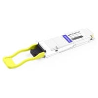
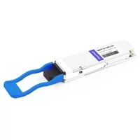
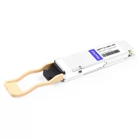
Send a request for “a 400G QSFP112 module” to three different vendors and you may receive three different recommendations. One vendor may quote a DR4. Another may suggest a DR4+. A third may ask about your installed fiber infrastructure and explain that neither option matches your deployment requirements.
That is not simply vendor confusion. QSFP112 modules use several overlapping naming systems, and some commonly used names are industry terms rather than IEEE-defined interface names. When a link fails to establish, a mismatch between the requested module type and the actual optical specification is one of the first things to verify.
QSFP112 is a form factor, not an optical specification. It defines the mechanical package and electrical interface requirements, but it does not determine whether the module uses multimode or single-mode fiber, which connector is required, or what transmission distance it supports. Those decisions are determined by the optical variant, and QSFP112 module types differ mainly in these areas.
This guide covers the five common optical variants, the LPO implementation approach that can be combined with different optical designs, common naming differences that lead to ordering mistakes, breakout capability as a key deployment consideration, and current 2026 pricing. For more background, see our complete QSFP112 400G guide.
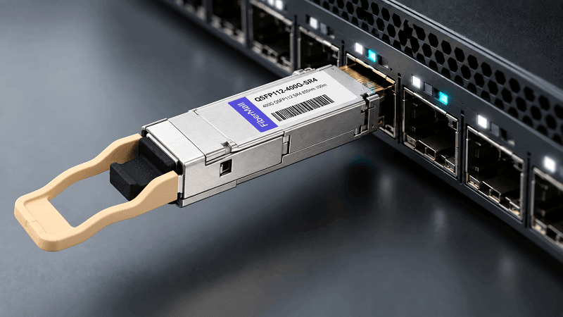
Quick Comparison: QSFP112 Module Types at a Glance
All five QSFP112 module types run four 100G-PAM4 lanes at 400G aggregate. Only media, reach, connector, power, and breakout capability change.
| Type | Media / Fiber | Reach | Connector | Wavelength | Power | Breakout-capable |
| VR4 | OM3/OM4/OM5 MMF | 30 m OM3 / 50 m OM4 | MPO-12/APC | 850 nm VCSEL | ~8 W | Yes |
| SR4 | OM3/OM4/OM5 MMF | ~60-70 m OM3 / 100 m OM4 | MPO-12/APC | 850 nm VCSEL | ~8 W | Yes |
| DR4 | OS2 SMF | 500 m | MPO-12/APC | ~1310 nm | 9-10 W | Yes |
| FR4 | OS2 SMF | 2 km | Duplex LC | CWDM 1271-1331 nm | 10-11 W | No |
| LR4 | OS2 SMF | 6 km / 10 km | Duplex LC | CWDM | 10-13.5 W | No |
| LPO (any) | per variant | ≤2 km practical | per variant | per variant | ≤6 W | per variant |
The last column is the one most buyers never check, and it is the one that occasionally breaks a network design. If a 400G switch port needs to feed four 100G servers, FR4 and LR4 are eliminated immediately regardless of how convenient their duplex LC interface looks.
What Makes Something a “QSFP112 Module Type”
One Form Factor, Many Optical Specifications
QSFP112 modules support four PAM4 lanes operating at approximately 106.25 Gb/s per lane, resulting in a 425 Gb/s line rate and 400G aggregate Ethernet bandwidth. The host electrical interface is typically based on 400GAUI-4 electrical specifications defined by IEEE 802.3ck. The mechanical package follows the QSFP112 MSA specification, maintaining the same width class as previous QSFP families while extending the module length to support higher-speed electrical requirements.
Because the electrical interface is standardized, the optical variant name describes the transmission characteristics. VR4, SR4, DR4, FR4, and LR4 share the same 400G electrical architecture but differ in:
- Laser technology
- Wavelength
- Fiber type
- Connector interface
- Transmission distance
- Power consumption
This is why a form-factor overview alone cannot determine whether a module fits a specific deployment environment.
Two management considerations apply across QSFP112 deployments. QSFP112 modules commonly use CMIS-based management interfaces, with newer CMIS revisions providing enhanced monitoring capabilities such as improved diagnostics and lane-level visibility. The supported CMIS version should always be verified against the target switch platform and module vendor specification.
The Two Axes Most Buyers Conflate
A QSFP112 order involves two independent decisions, but many selection guides only describe the optical variant.
Axis A is the optical variant.
This determines the physical transmission method:
- Multimode or single-mode fiber
- MPO or LC connector
- 30 m, 100 m, 500 m, 2 km, or longer reach
Axis B is the signal implementation.
QSFP112 modules may be built with conventional DSP-based architectures or LPO (Linear Pluggable Optics) designs. LPO removes the DSP from the optical module and relies on host-side SerDes processing.
These two choices are independent. For example, a QSFP112 SR4 can exist in either DSP or LPO versions. Both use the same fiber type and connector, but they differ in:
- Power consumption
- Latency
- Signal processing method
- Host compatibility requirements
Vendors that list only optical variants may hide this important implementation difference from buyers.
Multimode QSFP112 Module Types: VR4 and SR4
VR4: The 30-50 m Variant
VR4 is commonly used for very-short-reach 400G multimode applications. It uses 850 nm VCSEL technology over multimode fiber with an MPO-12/APC connector.
Typical reach:
- 30 m over OM3
- 50 m over OM4/OM5
Because of its shorter reach requirement, VR4 can provide a cost-effective solution for very short intra-rack or adjacent-rack connections.
SR4: The 50-100 m Default
SR4 uses the same 850 nm VCSEL technology and MPO-12/APC interface as VR4 but provides extended multimode reach.
Typical reach:
- Approximately 70 m over OM3
- Up to 100 m over OM4/OM5
Reach specifications may vary slightly between vendors, so the module datasheet should always be checked before deployment.
VR4 vs SR4: Key Differences
The main difference between VR4 and SR4 is transmission distance rather than electrical architecture. Both support four 100G PAM4 lanes and use multimode fiber.
Choose VR4 when:
- The link distance is very short
- Existing cabling length requirements are below SR4 capability
- Cost optimization is a priority
Choose SR4 when:
- Longer multimode reach is required
- Existing OM4/OM5 MPO cabling infrastructure is available
- Additional link margin is desired
A brownfield data center with existing QSFP28-SR4 OM4 MPO-12 cabling can often migrate to QSFP112-SR4 without replacing the fiber infrastructure, simplifying the transition to 400G networking.
Parallel Single-Mode QSFP112 Module Types: DR4
DR4: 500 m Over 8 of 12 Fibers
DR4 (400GBASE-DR4) uses 1310 nm optical transmission over single-mode fiber and supports a typical reach of 500 m with a 3 dB link budget. Power consumption is generally around 9-10 W.
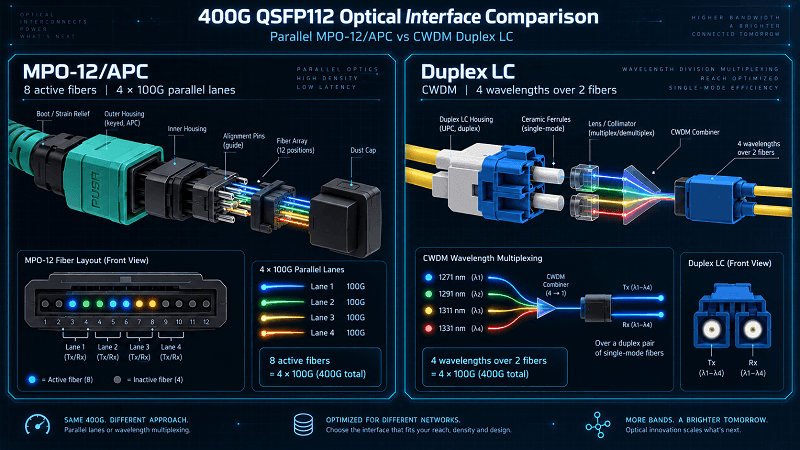
It uses four transmit and four receive fibers through an MPO-12/APC connector. Although only eight fiber positions carry optical signals, the physical connector remains an MPO-12 interface.
DR4 is widely adopted in data center leaf-spine architectures because it provides:
- Single-mode transmission capability
- 500 m reach
- MPO-based structured cabling compatibility
- Breakout support for lower-speed connections
DR4 vs SR4: Single-Mode or Multimode?
The choice between DR4 and SR4 usually depends more on the existing fiber infrastructure than on the optical modules themselves.
Choose DR4 when:
- The installed cabling is OS2 single-mode fiber
- The link distance exceeds multimode capability
- Breakout capability is required
- The deployment needs a scalable single-mode architecture
Choose SR4 when:
- OM3/OM4/OM5 multimode cabling already exists
- The link distance remains within multimode reach limits
- Existing MPO multimode infrastructure should be reused
The price difference between DR4 and SR4 is usually smaller than the cost impact of changing the fiber plant. Selecting the correct fiber architecture is often more important than the module price itself.
The MPO-8 vs MPO-12 Connector Confusion
One common procurement mistake comes from confusing active fiber count with connector type.
A DR4 module uses eight active fibers:
- 4 transmit lanes
- 4 receive lanes
However, the module interface is still an MPO-12/APC connector, with four unused fiber positions.
The number of active fibers does not mean the connector should be specified as MPO-8. Buyers should order MPO-12/APC patch cables unless the vendor explicitly confirms another interface.
Connector polish is equally important. QSFP112 parallel optical interfaces commonly use APC polishing, and using incorrect polish types can introduce excessive back reflection, signal degradation, and link instability.
Breakout Is a Major DR4 Advantage
DR4 is one of the primary 400G optical solutions supporting breakout architectures.
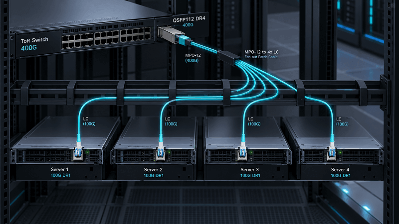
A 400G DR4 port can typically support:
- 2×200G connections
- 4×100G connections
This makes DR4 suitable for environments where 400G switches connect to multiple lower-speed servers or network devices.
A 400G port connecting directly to another 400G switch can also use DR4 when the distance requirement is within the 500 m range.
Using one optical type for both direct 400G links and breakout scenarios can simplify inventory management in large-scale deployments.
Duplex Single-Mode QSFP112 Module Types: FR4 and LR4
FR4: 2 km Over Duplex LC Fiber
FR4 (400GBASE-FR4) uses four CWDM wavelengths:
- 1271 nm
- 1291 nm
- 1311 nm
- 1331 nm
These four wavelengths are multiplexed over a duplex LC single-mode fiber pair.
Typical specifications:
- Reach: 2 km
- Fiber: OS2 single-mode fiber
- Connector: Duplex LC
- Link budget: approximately 4 dB
- Power consumption: around 10 W
FR4 is suitable for deployments where:
- Existing infrastructure uses duplex LC single-mode cabling
- MPO-based parallel fiber systems are not available
- Longer reach than DR4 is required without moving to LR4
Campus networks, telecom interconnects, and enterprise environments with LC-based single-mode cabling are common FR4 applications.
LR4: 6 km or 10 km Depending on the Specification
LR4 is one of the most confusing QSFP112 naming areas because different industry specifications use different distance definitions.
Two common implementations exist:
400GBASE-LR4-6
Defined by IEEE 802.3cu:
- Reach: 6 km
- Duplex LC interface
- CWDM wavelength technology
400G-LR4-10
Defined by the 100G Lambda MSA:
- Reach: 10 km
- Duplex LC interface
- CWDM wavelength technology
Both may appear in vendor catalogs as “LR4.”
Therefore, a purchase request specifying only:
QSFP112 LR4
may not provide enough information.
For deployments beyond 6 km, the required distance should always be explicitly stated in the purchase order and confirmed with the supplier.
FR4 and LR4 Cannot Break Out
FR4 and LR4 use wavelength multiplexing over a duplex LC fiber pair.
Unlike DR4, their four optical lanes are combined through WDM technology rather than exposed as independent parallel fiber channels.
Therefore:
- 2×200G breakout is not supported
- 4×100G breakout is not supported
Cable adapters cannot convert FR4 or LR4 into a breakout solution.
If breakout capability is part of the future network plan, a parallel-fiber solution such as DR4 should be evaluated instead.
The Naming Traps: Multiple Naming Systems, One Module
This is where many incorrect orders originate. QSFP112 modules can reach the same 400G bandwidth while using different naming conventions depending on optical architecture, vendor terminology, or industry standards.
Trap 1: DR4 vs DR4+ vs DR4++
| Label | Reach | IEEE standard? | Other vendor names |
| DR4 | 500 m | Yes, 400GBASE-DR4 | None needed |
| DR4+ | 2 km | No | XDR4, EDR4, 4×FR1, 4XFR |
| DR4++ | 10 km | No | PLR4, 4XLR |
Only 400GBASE-DR4 is an IEEE-defined interface.
DR4+ and DR4++ are industry naming terms used by vendors to describe extended-reach variants.
When ordering, specify the actual reach requirement rather than relying only on the DR4 naming.
Trap 2: LR4-6 vs LR4-10
As described earlier, LR4 may refer to different distance classes.
Always confirm:
- Required transmission distance
- Applicable standard
- Vendor part number
Trap 3: MPO-8 vs MPO-12
Eight active fibers do not mean an MPO-8 connector.
For QSFP112 DR4 and SR4:
- Connector: MPO-12/APC
- Active fibers: 8
Ordering should specify the connector type, not only the number of active lanes.
Trap 4: FR1 vs FR4
FR1 and FR4 have similar names but completely different architectures.
FR1
- Parallel 1310 nm lanes
- MPO connector
- Designed for parallel fiber transmission
FR4
- Four CWDM wavelengths
- Duplex LC connector
- WDM-based transmission
A buyer who assumes FR1 is simply a derivative of FR4 may select the wrong cabling system.
The key difference is:
FR1 uses parallel fiber. FR4 uses wavelength multiplexing.
Low-Power Builds: DSP vs LPO
What LPO Changes
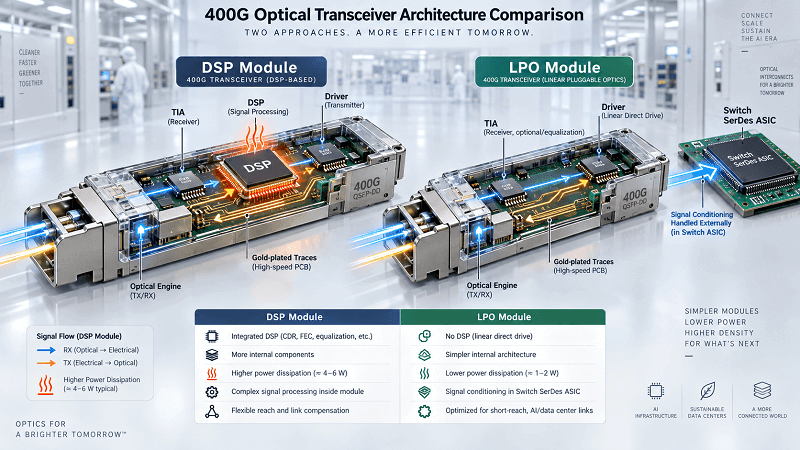
An LPO (Linear Pluggable Optics) QSFP112 module removes the DSP (Digital Signal Processor) from the optical module. Signal equalization and retiming functions are moved to the host switch ASIC or SerDes architecture, making the optical module a more analog-oriented design.
The main benefits include:
- Lower module power consumption
- Reduced signal processing latency
- Simplified optical module architecture
Compared with traditional DSP-based modules, LPO designs can reduce module power from approximately 8-12 W to around 6 W or below, depending on the optical variant.
However, the trade-off is that the host system must provide sufficient signal integrity and be qualified for linear optical channels. Because there is less compensation inside the module, LPO deployment is generally more suitable for shorter-reach applications.
LPO Reach and Deployment Considerations
LPO is not a direct replacement for every DSP-based QSFP112 module.
It is typically considered for:
- Short-reach data center links
- High-density switch environments
- Systems with strict power and thermal requirements
- Platforms where the host SerDes has been validated for LPO operation
LPO is generally not suitable for:
- Long-distance 400G links
- Systems without LPO-qualified SerDes channels
- Deployments requiring maximum optical margin
The LPO MSA was established in 2024 to promote interoperability and standardization of linear optical module designs. The ecosystem continues to develop as switch ASIC and optical module vendors improve compatibility.
Worked Link Budgets
Headline reach specifications represent ideal test conditions. Real deployments introduce additional losses from:
- Connector insertion loss
- Fiber attenuation
- Patch panels
- Splices
- Cable quality variations
Therefore, link design should always consider the complete optical budget rather than relying only on the advertised distance.
Typical optical budgets include:
- VR4: approximately 1.7 dB
- SR4: approximately 1.8 dB
- DR4: approximately 3 dB
- FR4: approximately 4 dB
How to Choose a QSFP112 Module Type
Start With the Fiber Plant, Not the Module
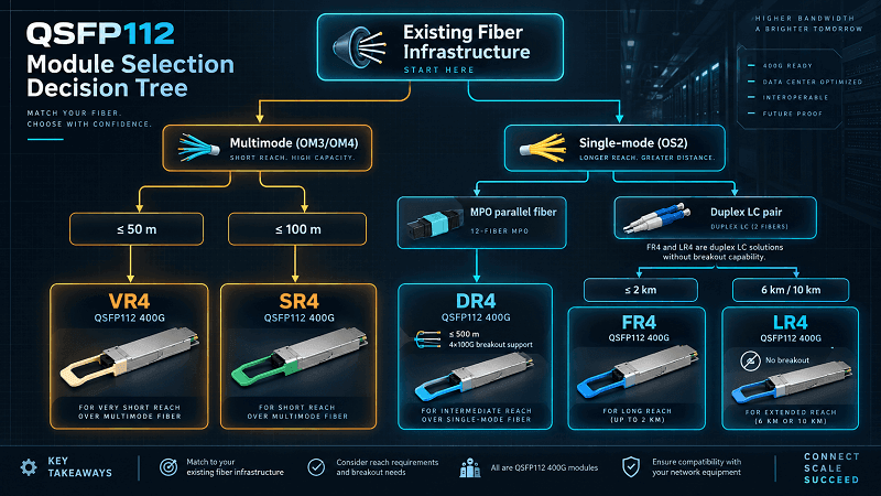
Most selection guides for QSFP112 module types begin with the module and work backwards. The correct order is the reverse:
1. What fiber is already installed? OM3, OM4, OM5, or OS2.
2. What connector exists at the patch panel? MPO-12 or duplex LC.
3. What is the actual span length? Measured, not estimated.
4. Is breakout required now or soon? If yes, only DR4 and VR4 qualify.
5. Is the host SerDes qualified for LPO? If not, buy DSP.
Decision Matrix
| Installed plant | Distance | Breakout needed? | Type |
| OM3/OM4 MPO-12 | ≤100 m | No | SR4 |
| OM3 | ≤30 m | No | VR4 |
| OM4 MPO-12 | ≤100 m | Yes | SR4 (limited) or DR4 |
| OS2 MPO-12 | ≤500 m | Yes | DR4 |
| OS2 duplex LC | ≤2 km | No | FR4 |
| OS2 duplex LC | 6-10 km | No | LR4 (confirm LR4-6 vs LR4-10) |
| Any, ≤2 km, power-constrained | ≤2 km | No | LPO SR4/DR4 |
Two patterns from real deployments illustrate why the plant comes first. A brownfield enterprise data center with existing QSFP28-SR4 OM4 MPO-12 trunks moved to 400G on QSFP112-SR4 with no new cabling. An AI training team that needed to split 400G ports into 8×200G standardized on DR4 across the fabric and never considered multimode, because breakout capability drove the choice before reach did.
If you are still deciding on the package itself, our QSFP-DD vs QSFP112 decision guide compares lane count, power, and upgrade path before you get to variant selection.
What the QSFP112 Module Types Do Not Include
Buyers search for parts that don’t exist in this form factor, and no page explains why. Four absences are worth stating plainly.
No 400G-ER4. There is no QSFP112 part reaching 30-40 km. Extended-reach 400G is QSFP-DD or OSFP territory.
No QSFP112 SR4.2. The 850/910 nm bidirectional multimode standard (IEEE 802.3cm) is implemented in QSFP-DD and OSFP, not QSFP112, in every catalogue reviewed.
No 800G. Four 112G lanes top out at 400G. 800G requires eight 100G-PAM4 lanes in a larger package.
No single-lambda 400G. QSFP112 is a four-lane form factor by definition.
If a design assumes any of these, the problem is the form factor, not the module type. Our 400G form factor comparison covers which package handles which reach class.
One caution on datasheets: vendor documents occasionally print contradictory host-interface labels for QSFP112 LR4, sometimes listing an 8-lane interface alongside four lanes. QSFP112 is 400GAUI-4. Do not repeat a vendor interface typo in a specification.
Cost by QSFP112 Module Type (2026)
FiberMall list prices as of September 2026. The spread across the QSFP112 module types is narrower than most buyers expect.
| Module | List price |
| QSFP112-400G-VR4, 850 nm, 50 m, MPO-12 | $385 |
| QSFP112-400G-SR4, 850 nm, 100 m, MPO-12 | $400 |
| QSFP112-400G-DR4, 1310 nm, 500 m, MPO-12 | $500 |
| QSFP112-400G-FR1 (4×100G), 1310 nm, 2 km, MPO-12 | $800 |
| QSFP112-400G-FR4, CWDM, 2 km, Duplex LC | $600 |
| QSFP112-400G-LR4, CWDM, 10 km, Duplex LC | $1,000 |
| LPO QSFP112-400G-SR4, 850 nm, 50 m | $800 |
| LPO QSFP112-400G-DR4, 500 m | $1,200 |
| LPO QSFP112-400G-FR4, CWDM, 2 km | $1,350 |
Framed by cost per meter of reach, VR4 and SR4 dominate under 100 m, and DR4 wins the 200-500 m band. FR4 then takes 500 m to 2 km on a duplex plant, while LR4 is the only answer past 6 km.
Note the price level itself. Older vendor content still circulates a 600−900 benchmark for a generic 400 GSR4 module. FiberMall’s current list is 400, roughly 30% below that anchor. Prices in this band have moved down, and any budget built on 2024 or 2025 figures should be re-quoted.
Conclusion
QSFP112 module types are simpler than the catalogue makes them look. Five optical variants share one four-lane, 100G-PAM4 form factor, and a sixth decision (DSP or LPO) sits independently on top.
Four naming systems obscure that simplicity, and two of the names in daily use are not IEEE standards. The DR4 ladder, the LR4-6 versus LR4-10 split, the MPO-8 phantom, and FR1 versus FR4 each cause wrong orders that a careful purchase order prevents.
Breakout capability, meanwhile, is binary and should lead the decision rather than follow it. DR4 and VR4 break out. FR4 and LR4 do not.
Start with the fiber in your floor, work out to the connector, measure the span, and only then pick the type. If that order feels backwards, it is because most guides describe modules instead of networks.
Explore FiberMall’s full 400G QSFP112 range → VR4, SR4, DR4, FR1, FR4, LR4, and LPO builds are all in stock. Our engineers will confirm compatibility against your switch platform and fiber plant before you order, and color-matched QSFP112 AOC cables are available for the same builds.
FAQ
What are the types of QSFP112 modules?
QSFP112 modules commonly include five major optical variants:
- VR4: multimode fiber, approximately 30-50 m
- SR4: multimode fiber, up to 100 m
- DR4: single-mode fiber, approximately 500 m
- FR4: single-mode CWDM, approximately 2 km
- LR4: single-mode CWDM, approximately 6-10 km depending on specification
All support four 100G-class electrical lanes for 400G aggregate bandwidth. They mainly differ in fiber type, connector interface, wavelength technology, reach, and power consumption.
What is the difference between QSFP112 SR4 and VR4?
SR4 and VR4 use similar optical technology:
- 850 nm VCSEL
- Multimode fiber
- MPO-12/APC interface
The primary difference is transmission distance.
VR4 is designed for very-short-reach applications, while SR4 provides longer multimode reach, typically up to 100 m over OM4/OM5 fiber.
The appropriate choice depends on the required distance and installed cabling infrastructure.
What is the difference between QSFP112 DR4 vs SR4?
DR4 and SR4 use different fiber architectures.
DR4:
- 1310 nm transmission
- OS2 single-mode fiber
- Approximately 500 m reach
- MPO interface
- Supports breakout applications
SR4:
- 850 nm VCSEL
- OM3/OM4/OM5 multimode fiber
- Up to approximately 100 m reach
- MPO interface
Choose DR4 when longer distance, single-mode infrastructure, or breakout capability is required.
Choose SR4 when existing multimode cabling can support the required distance.
What is the difference between QSFP112 DR4, DR4+, and DR4++?
These names describe different reach classes used by vendors.
- DR4: 500 m, IEEE standardized as 400GBASE-DR4
- DR4+: approximately 2 km, vendor terminology
- DR4++: extended reach variants, commonly referring to longer-distance implementations
Only DR4 is an IEEE-defined interface name.
For procurement, always confirm:
- Exact transmission distance
- Optical specification
- Vendor part number
Is QSFP112 LR4 6 km or 10 km?
Both versions exist.
400GBASE-LR4-6:
- Defined by IEEE 802.3cu
- Reach: 6 km
400G-LR4-10:
- Defined by the 100G Lambda MSA
- Reach: 10 km
Because vendors may use the LR4 name differently, always specify the required distance when ordering.
Does QSFP112 use MPO-8 or MPO-12?
QSFP112 parallel optical modules such as DR4 and SR4 use:
- MPO-12/APC connectors
- Eight active fiber positions
The term MPO-8 usually refers to the number of active fibers rather than the physical connector.
Always confirm connector type before ordering fiber assemblies.
Which QSFP112 module types support breakout?
DR4 is the primary QSFP112 breakout solution.
Typical breakout scenarios include:
- 400G to 4×100G
- 400G to 2×200G
Some VR4 implementations may also support breakout depending on the module design and switch platform.
FR4 and LR4 do not support lane-based breakout because they use WDM transmission over duplex LC fiber.
Is there an LPO QSFP112 module?
Yes. LPO QSFP112 modules are available for selected optical variants, including SR4, DR4, and FR4 implementations.
Compared with DSP-based modules, LPO designs can reduce power consumption by removing the module DSP.
However, deployment requires:
- Compatible switch ASIC
- Qualified SerDes channel
- Appropriate link distance
Does QSFP112 have an ER4 or 800G option?
No standard QSFP112 ER4 or 800G option exists.
QSFP112 is designed around a four-lane 400G architecture.
For:
- 30-40 km 400G transmission
- 800G networking
other form factors such as QSFP-DD or OSFP are typically used.
Related Products:
-
 QSFP112-400G-SR4 400G QSFP112 SR4 PAM4 850nm 100m MTP/MPO-12 OM3 FEC Optical Transceiver Module
$400.00
QSFP112-400G-SR4 400G QSFP112 SR4 PAM4 850nm 100m MTP/MPO-12 OM3 FEC Optical Transceiver Module
$400.00
-
QSFP112-400G-DR4 400G QSFP112 DR4 PAM4 1310nm 500m MTP/MPO-12 with KP4 FEC Optical Transceiver Module
$500.00
-
QSFP112-400G-FR1 4x100G QSFP112 FR1 PAM4 1310nm 2km MTP/MPO-12 SMF FEC Optical Transceiver Module
$800.00
-
QSFP112-400G-FR4 400G QSFP112 FR4 PAM4 CWDM 2km Duplex LC SMF FEC Optical Transceiver Module
$600.00
-
QSFP112-400G-LR4 400G QSFP112 LR4 PAM4 CWDM 10km Duplex LC SMF FEC Optical Transceiver Module
$1000.00
-
FiberMall QSFP112-400G-VR4 Compatible 400G QSFP112 VR4 PAM4 850nm 50m MTP/MPO-12 OM4 FEC Optical Transceiver Module
$385.00