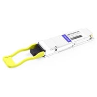
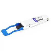
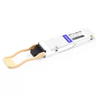
Fill a 32-port 400G leaf switch with QSFP112 optics and the transceivers alone can draw roughly 256 to 384 watts with common 8–12 W modules. With higher-power long-reach optics approaching 13.5 W, the total can reach about 432 W. Nearly all of that electrical power ultimately becomes heat inside the rack. The switch PSU, PDU, airflow design and facility cooling system all have to absorb it.
That is why a single QSFP112 power-consumption figure such as “8 to 12 W” is not enough for system planning. It does not tell you which variant fits a 500 m run, where the heat is generated inside the module, or what the rack will cost to operate over a year.
This guide breaks down QSFP112 power consumption by module variant, explains the DSP-versus-optics contribution, discusses temperature and airflow constraints, and walks through watts-to-dollars calculations at pod scale. If you want the module fundamentals first, the complete QSFP112 400G guide covers speeds, variants and form factor.
One scoping note up front: the methods for rack-power calculation, PDU sizing and generic thermal planning already appear in our QSFP28 and QSFP-DD power guides. This page focuses on QSFP112-specific numbers. Where the methodology is shared, we link to those guides instead of repeating it.
Quick Answer: How Much Power Does QSFP112 Use?
A 400G QSFP112 optical module commonly draws around 8–12 W, depending on the implementation and reach. Multimode SR4/VR4 modules are often around 8–9 W, single-mode DR4/FR4 modules are commonly around 9–11 W, and some long-reach LR4 implementations can reach approximately 13.5 W. LPO implementations can reduce module power substantially, with some products falling in roughly the 3–6 W range.
For a 32-port switch, common 8–12 W optics correspond to approximately 256–384 W of optics-only power. A 13.5 W-per-port long-reach configuration would reach about 432 W. For infrastructure planning, use the maximum specified power of the actual module mix rather than only the typical value, then apply the headroom required by your electrical design.
Two factors explain why QSFP112 power is a range rather than a single number. First, DSP architecture, optical technology, laser type and transmission reach all affect power. Second, actual module consumption and thermal margin can vary with operating conditions, so the typical data-sheet figure and the worst-case system-planning figure are not necessarily the same.
Keep reading if you are sizing a PSU, PDU or cooling system, because that is where the difference matters.
QSFP112 Power Consumption by Module Type
The Per-Variant Table
No single vendor publishes every QSFP112 variant in one universal table, which is why broad “8 to 12 W” estimates are common. The following values are useful planning bands rather than universal limits.
| Variant | Reach | Typical | Max | Heat load at max |
| VR4 | 30/50 m OM3/OM4 | ~8 W | 9 W | 30.7 BTU/hr |
| SR4 | 60–100 m OM4 | ~8 W | 9 W | 30.7 BTU/hr |
| DR4 | 500 m SMF | 9–10 W | 10 W | 34.1 BTU/hr |
| FR4 | 2 km SMF | 10–11 W | 11 W | 37.5 BTU/hr |
| LR4 | 6–10 km SMF | 10–13.5 W | 13.5 W | 46.1 BTU/hr |
| LPO (any) | ≤2 km | ≤6 W | 6 W | 20.5 BTU/hr |
The difference between a short-reach 8 W module and a 13.5 W long-reach module is approximately 1.7×. That becomes significant when multiplied across dozens or hundreds of ports.
Vendors can also differ by roughly a watt or more within the same optical category because DSP architecture, component selection, link-budget targets and characterization methods vary. Cisco, for example, lists around 9 W for selected 400G QSFP112 VR4, DR4 and FR4 products.
Treat these figures as planning bands based on products available as of September 2026, not as universal specifications. The data sheet for the exact part number should always be the final reference.
Why the Same “Type” Spans Three Power Classes
Reach is only one variable.
Products within the broader DR4 family, for example, can show different power requirements as vendors add link-budget margin, support extended-distance variants, use different DSP generations or change the optical engine. Similar optical naming therefore does not guarantee identical electrical power.
There is also a hardware power-delivery constraint behind the module design. QSFP112 uses multiple 3.3 V supply contacts, and each supply contact has its own current rating. High-power module designs must distribute current across the available Vcc contacts without exceeding the per-contact limits defined by the form-factor specification.
This is why system designers should use the module’s declared maximum power and host power-delivery capability rather than estimating compatibility from optical reach alone.
A common planning mistake is to standardize on long-reach optics for fiber simplicity while budgeting power as though every port were populated with short-reach modules. At rack scale, that difference can materially change both electrical and thermal requirements.
Power Class as a Budget Line
QSFP112 sits at CMIS Power Class 6, up to 12 W. A QSFP28 link at the far end of a breakout sits at Class 5, up to 5 W. A cage that can’t source the advertised class won’t initialize the module at all, and that’s a hardware limit rather than a firmware one.
We cover the gate itself in the QSFP112 compatibility and power-class rules. Here, just treat the class as a line item: every QSFP112 port you light needs a cage that can feed 12 W, even if the module in it only wants 8 W today. The per-variant reach, connector, and link-budget detail lives in QSFP112 module types; this table is the numeric home only.
Where the Watts Go: The 4-Lane Advantage
Fewer Lanes, Less Logic
A 400G QSFP112 interface carries approximately 400G using four ~106.25 Gb/s PAM4 electrical lanes over a 400GAUI-4-class host interface.
By comparison, many earlier 400G QSFP-DD implementations use eight ~50G-class PAM4 electrical lanes. However, OSFP should not be treated as inherently eight-lane at 400G: depending on the generation and product, 400G OSFP implementations may use either four higher-speed lanes or eight lower-speed lanes.
Reducing the host electrical lane count from eight lanes to four can reduce the amount of SerDes and DSP circuitry required and simplify parts of the electrical architecture. That can contribute to lower power consumption.
However, lane count is only one factor. DSP process technology, equalization requirements, FEC architecture, optical-engine design, laser technology, driver/TIA efficiency and transmission reach can all materially affect module power.
So the four-lane architecture is an important contributor to QSFP112 efficiency, but it is not the only reason one module may consume less power than another.
For the broader form-factor comparison, see QSFP112 vs OSFP and QSFP-DD vs QSFP112.
The DSP Share Is the Story
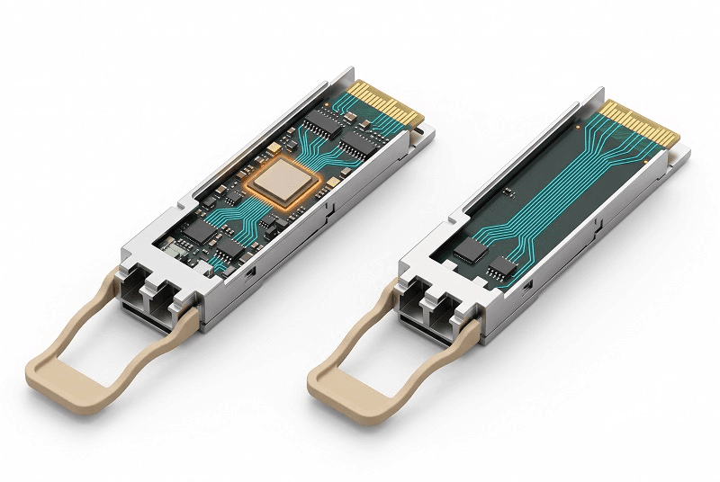
The DSP can be one of the largest individual power consumers inside a retimed 400G optical module.
In some implementations, the DSP alone can account for several watts of module power. The remaining power is distributed across the optical engine, laser, drivers, TIAs, control circuitry and power-conversion components.
That is why linear pluggable optics, or LPO, can significantly reduce QSFP112 module power. LPO removes the conventional module-side DSP or retimer and relies more heavily on the host SerDes for signal equalization.
Depending on implementation, LPO QSFP112 modules can operate at substantially lower power than comparable DSP-based optics, with some products in roughly the 3–6 W range versus approximately 8–12 W for many conventional retimed modules.
The exact percentage reduction varies by product, so a fixed “30–50 percent” value should be treated as an approximate range rather than a universal rule.
The LPO MSA was established in March 2024, with NVIDIA among its founding members. The broader PAM4 DSP thermal methodology is discussed in our QSFP56 power and thermal design guide.
For a watts-per-gigabit and pJ/bit comparison across optical generations, see the per-gigabit efficiency guide. This article stays focused on QSFP112 watts at scale.
QSFP112 Thermal Management: Derating and MTBF
Power and Temperature
A module that draws 8 W in a 25 °C aisle does not draw 8 W in a 45 °C one. Internal bias and DSP power climb as ambient climbs, and the house figure we use for this generation is on the order of 18 percent more from 25 °C to 70 °C, with internal module temperature running well above ambient at the top of the range.
MSA thermal grades are commercial (0 to +70 °C), extended (−5 to +85 °C), and industrial (−40 to +85 °C). Most data center aisles run the standard commercial grade, so plan derating against 0–70 °C. The full temperature-class ladder is in the QSFP28 thermal planning guide; for QSFP112, just confirm you’re buying the grade your aisle actually sees.
MTBF Is Also a Thermal Decision
Higher component temperatures generally accelerate many semiconductor and optoelectronic failure mechanisms.
However, there is no universal rule stating that every 5 °C reduction in QSFP112 temperature produces a fixed percentage improvement in MTBF. Reliability improvement depends on the component technology, activation energy and dominant failure mechanism.
The practical conclusion remains valid: keeping optics comfortably within their specified thermal range generally improves reliability margin and reduces the likelihood of thermally induced degradation or shutdown.
Across a fabric with hundreds or thousands of ports, better thermal management can therefore affect both electricity consumption and long-term replacement costs.
Airflow: Turning Watts Into Cooling Requirements
The Airflow Requirement
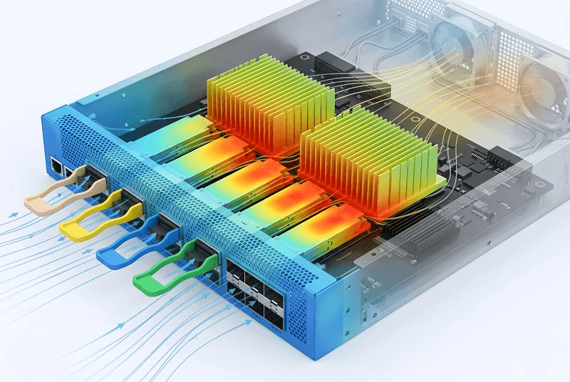
Few optical-module data sheets specify one universal airflow requirement because the required airflow depends heavily on the host design.
Broadcom documentation for AI-cluster networking hardware, for example, provides airflow conditions such as approximately 200 LFM at 25 °C and 250 LFM at 35 °C for specific test configurations using lower-power optics. The same documentation notes that the connector may support higher-power optics, but higher optical power requires additional thermal evaluation and potentially greater airflow.
Therefore, those LFM values should not be interpreted as a universal airflow requirement for every 12 W QSFP112 module.
QSFP112 heat generation tracks electrical power closely: almost all module input power ultimately becomes heat. But there is no universal conversion such as “0.145 CFM per watt” that applies to every switch or NIC.
Required airflow depends on factors including:
- allowable air-temperature rise,
- cage and heatsink thermal resistance,
- module orientation,
- airflow direction,
- inlet temperature,
- altitude and air density,
- local flow impedance,
- adjacent high-power modules.
For that reason, system designers should follow the switch, NIC or server vendor’s qualified airflow and thermal limits rather than converting module watts directly into a universal CFM value.
Here is the part people often miss: the cage, heatsink and host thermal design can be the limiting factor even when the module itself is within its electrical power rating.
The Air-Cooling Ceiling
High-density servers can run into significant thermal constraints with high-power QSFP112 adapters and optics.
Lenovo’s SR650 V4 documentation, for example, applies 25 °C or 30 °C ambient limits to certain configurations depending on fan count, storage, GPU configuration, adapter type and transceiver population.
This illustrates an important point: adding more airflow does not automatically override a system vendor’s qualified ambient-temperature limit.
If a platform is specified for a maximum ambient temperature under a particular accelerator, NIC and optics configuration, operation beyond that limit requires a different qualified configuration or cooling architecture.
At very high rack density, direct liquid cooling for CPUs and GPUs can free additional air-cooling capacity for NICs and optics, while specialized thermal solutions may also be required around the optical interfaces themselves.
The correct solution depends on the complete server or switch thermal architecture rather than the optical module alone.
Switch and Rack Level: From Watts to BTU/hr
Real Switch Anchors
Vendor switch data sheets help show how optics contribute to rack-level power.
One documented 128 × 400GE QSFP112-class switch configuration reaches approximately 2,425 W / 8,275 BTU/hr under a fully loaded short-reach configuration and approximately 3,197 W / 10,909 BTU/hr in a higher-power long-reach configuration at elevated temperature.
These figures include the complete switch—not only the optics—so the resulting per-port number includes ASIC, fans, power conversion and other platform overhead.
A second vendor example, the Hohunet S8532-EI, is listed around 383 W, approximately 1,307 BTU/hr. Ten such switches would therefore represent roughly 3.83 kW or 13,070 BTU/hr before any additional design margin.
These vendor examples should be used as platform references rather than universal QSFP112 switch-power values.
The Optics-Only Math
If you only want the transceiver load, the arithmetic is simple and worth doing three ways, because the variant choice moves it a lot:
- 32-port, LPO: 192 W, about 655 BTU/hr
- 32-port, standard DSP: 320 W, about 1,092 BTU/hr
- 32-port, long-reach: 384 W, about 1,311 BTU/hr
At 128 ports the same ladder runs 1,024 to 1,280 W for QSFP112 against 1,280 to 1,536 W for the QSFP-DD equivalent. The conversion constant is fixed: BTU/hr = watts × 3.412.
An engineer we spoke with sized a QSFP112 leaf on typical watts and stopped at the conventional 80 percent PDU rule. During a link-flap retrain storm, every module jumped toward its maximum at once and the branch breaker tripped. His headroom was real on paper and gone in practice, because he’d planned to typical rather than to max-at-temperature.
The planning rule that survives contact with a retrain storm: size for the worst-case module mix, then add 20 percent. The OCP convention formalizes it, with de-rated power at 80 percent of maximum and PDUs sized at 120 percent of de-rated. The full PDU-sizing formula and the air-versus-liquid decision framework live in the QSFP-DD power and thermal guide.
Pod-Level QSFP112 Power Consumption and Electricity Cost
Worked Example
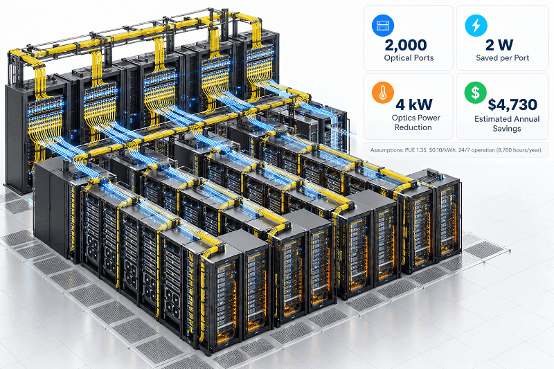
Now scale the difference across a 2,000-port AI fabric moving from a higher-power optical implementation to QSFP112 modules that save a conservative 2 W per port.
- Optical delta: 2,000 ports × 2 W = 4,000 W, or 4 kW saved
- At a PUE of 1.35: facility load avoided = 4 kW × 1.35 = 5.4 kW
- Annual energy: 5.4 kW × 8,760 hours = 47,304 kWh per year
- At $0.10/kWh: approximately $4,730 per year
Nearly $5,000 per year comes from only a 2 W-per-port difference.
The numbers scale linearly. A 4 W-per-port delta approximately doubles the savings, and a 4,000-port fabric approximately doubles them again.
That makes module power a meaningful procurement and infrastructure-planning variable rather than only a transceiver specification.
The 2-Channel Breakout Lever
There is another power lever that can be overlooked because it depends on configuration rather than simply purchasing a different module.
NVIDIA’s 400G SR4 QSFP112 multimode optic supports a 1:2 breakout mode. In the documented two-channel operating mode, maximum module power can fall from approximately 8.5 W in four-channel operation to about 5.5 W in two-channel operation.
That is a reduction of roughly 3 W per affected module.
Applied across a 128-port leaf where more than 40 ports operate in the 2×200G pattern, that difference can remove well over 100 W of optics load.
The breakout mechanics themselves are covered elsewhere in this content cluster; this article focuses on the power impact.
AI-Rack Reality
The AI rack is where all of these constraints meet.
OCP’s OPG-M architecture discusses rack-level power limits and power-planning assumptions for high-density infrastructure, while modern xPU servers consume the majority of the rack budget.
Optical modules represent a smaller share of total rack power, but at high density they can still consume hundreds of watts per switch and several kilowatts across a pod.
That makes lower-power optics especially valuable when a deployment is already close to its electrical or thermal limit.
LPO should therefore be viewed not only as a per-module power-saving technology but also as one possible way to reduce cumulative thermal load across large optical fabrics.
It does not automatically eliminate the need for advanced cooling, because CPUs, GPUs, switches and NICs still dominate overall system power. But every watt removed from the optical layer reduces both direct electrical demand and the corresponding cooling load.
QSFP112 modules operate from a nominal 3.3 V supply architecture, while the host PSU converts facility input power into the rails required by the switch or server. When moving from module-level watts to facility-level energy, include PSU conversion efficiency and PUE where appropriate.
Our QSFP112 in NVIDIA AI clusters guide covers the specific MMS1X00 and MMA1Z00 part numbers and their power figures.
Reducing QSFP112 Power Consumption in Practice
The Levers, In Order of Payoff
- Move to LPO where the host and reach requirements allow it. Removing the module-side DSP can produce a substantial reduction in transceiver power.
- Use short- or mid-reach optics instead of LR4 where the fiber plant permits it. An 8 W short-reach module versus a 13.5 W long-reach module represents roughly a 1.7× difference in module power.
- Use reduced-channel or breakout operating modes where supported by both the module and topology. Certain modules consume less power when fewer optical/electrical channels are active.
- Size cooling and airflow to the real module mix. Do not assume that every future configuration has the same thermal profile, but make sure the cooling design covers the maximum approved configuration.
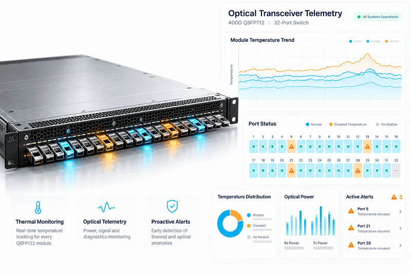
- Use module temperature telemetry to identify hot ports early. Configure operational alerts with sufficient margin below the vendor’s maximum case-temperature limit rather than using one universal temperature offset for every product.
What Not to Do
Do not size the rack using typical module watts alone.
Use the maximum specified power of the expected module population and apply the electrical and thermal design margin required by your platform and facility.
Do not assume that a host can power any QSFP112 module simply because the module physically fits the cage. Confirm the host’s supported module power and CMIS behavior.
And do not assume that lower-power optics eliminate host thermal limits. The switch, NIC, heatsink, fan system and ambient specification still determine whether the complete configuration is supported.
The cheapest watt is still the watt you do not have to power or cool.
QSFP112 Rack Power Planning Checklist
Work through these steps in order:
- Identify the highest-power module variant expected in the rack.
- Sum the maximum specified power across all populated optical ports.
- Add switch, NIC, server and other platform power to calculate total rack draw.
- Convert watts to BTU/hr using watts × 3.412 where a heat-load figure is required.
- Confirm the host vendor’s airflow, case-temperature and ambient-temperature limits.
- Apply the PDU headroom or de-rating method required by your facility design.
- Model facility power using your actual PUE and electricity rate.
- Configure module-temperature monitoring and track thermal trends over time.
Steps 1, 2 and 6 are where power-planning errors most often propagate through the rest of the rack design.
FAQ
How much power does a QSFP112 module consume?
A conventional 400G QSFP112 optical module commonly consumes around 8–12 W, depending on reach and implementation. Some long-reach modules can reach approximately 13.5 W, while LPO implementations can fall into roughly the 3–6 W range.
Is QSFP112 lower power than QSFP-DD?
It can be, but the difference depends on the exact modules being compared. Four-lane QSFP112 architectures can reduce electrical-lane and DSP complexity relative to earlier eight-lane 400G implementations, but optical technology, DSP generation and reach also affect total power.
What power class is QSFP112?
QSFP112 uses form-factor-specific power-class definitions. Modules above 5 W generally fall into the highest QSFP112 power-class category, while CMIS MaxPower provides the actual declared maximum-power requirement. Do not interpret QSFP112 power classes using the QSFP-DD power-class table.
Does QSFP112 power consumption increase with temperature?
Power consumption and thermal behavior can change with operating temperature, but there is no universal percentage increase that applies to every QSFP112 module. For planning, use the vendor’s maximum specified power and supported thermal conditions.
How much power do the optics in a 32-port QSFP112 switch consume?
Approximately 192 W at 6 W per port, 256 W at 8 W per port, 320 W at 10 W per port, 384 W at 12 W per port, or 432 W at 13.5 W per port. These figures cover the optics only and do not include switch ASICs, fans or PSU losses.
Does LPO reduce QSFP112 power consumption?
Yes. Removing the conventional module-side DSP can substantially reduce optical-module power. The exact saving depends on the product, host SerDes and optical implementation rather than one fixed percentage.
How do I convert QSFP112 watts to BTU/hr?
Multiply watts by 3.412.
For example:
320 W × 3.412 ≈ 1,092 BTU/hr
What is the maximum operating temperature of a QSFP112 module?
Commercial modules commonly specify approximately 0 to +70 °C module case temperature. Extended- or industrial-temperature products can support wider ranges depending on the manufacturer.
This should not be confused with the switch or server inlet-air temperature. The host thermal design must keep the module case within its specified limit.
Conclusion
QSFP112 power planning comes down to several durable rules.
Plan from the maximum specified module power, not only from the typical number. Convert the resulting load into the thermal and electrical metrics required by your facility. Confirm host airflow, module case temperature and platform ambient limits rather than relying on a universal CFM-per-watt rule.
The four-lane QSFP112 architecture can reduce electrical complexity compared with earlier eight-lane 400G implementations, but lane count alone does not determine module power. DSP architecture, optics, reach and implementation all matter.
LPO provides one of the largest opportunities to reduce module-level power because it removes the conventional module-side DSP. Shorter-reach optics and reduced-channel operating modes can provide additional savings where the network topology allows them.
At one port, a difference of two or three watts looks small. Across hundreds or thousands of optical links, it becomes a meaningful electrical, thermal and operating-cost variable.
If you’re building the power and thermal case for a 400G deployment, FiberMall can help. Start with the 400G QSFP112 transceiver range, and look at the LPO QSFP112 SR4 modules for the low-power path.
Request a rack power and thermal review, and we’ll match the plan to your actual module mix and PDU headroom.
Related Products:
-
 QSFP112-400G-SR4 400G QSFP112 SR4 PAM4 850nm 100m MTP/MPO-12 OM3 FEC Optical Transceiver Module
$400.00
QSFP112-400G-SR4 400G QSFP112 SR4 PAM4 850nm 100m MTP/MPO-12 OM3 FEC Optical Transceiver Module
$400.00
-
QSFP112-400G-DR4 400G QSFP112 DR4 PAM4 1310nm 500m MTP/MPO-12 with KP4 FEC Optical Transceiver Module
$500.00
-
QSFP112-400G-FR1 4x100G QSFP112 FR1 PAM4 1310nm 2km MTP/MPO-12 SMF FEC Optical Transceiver Module
$800.00
-
QSFP112-400G-FR4 400G QSFP112 FR4 PAM4 CWDM 2km Duplex LC SMF FEC Optical Transceiver Module
$600.00
-
QSFP112-400G-LR4 400G QSFP112 LR4 PAM4 CWDM 10km Duplex LC SMF FEC Optical Transceiver Module
$1000.00
-
FiberMall QSFP112-400G-VR4 Compatible 400G QSFP112 VR4 PAM4 850nm 50m MTP/MPO-12 OM4 FEC Optical Transceiver Module
$385.00