Imagine an engineer named Priya troubleshooting a 400G QSFP112 port that suddenly went down at 2:10 a.m. The module appeared in the switch inventory, but the link indicator remained dark. After cleaning the MPO connector twice and replacing the patch cord, the link still would not come up.
Further investigation revealed that the module had not completed initialization. The host and transceiver were experiencing a compatibility or module-management issue, and the problem had nothing to do with the fiber.
This illustrative scenario highlights a common challenge in AI networking environments. Effective QSFP112 troubleshooting requires a systematic approach rather than trial and error. Capture the initial state, inspect the physical layer, examine telemetry, verify configuration, and check module compatibility. Skipping these steps can lead to unnecessary component replacements and prolonged downtime.
This guide focuses on the specific challenges of troubleshooting 400G QSFP112 transceivers with 100G-class electrical lanes. You will learn how to identify common symptoms, interpret diagnostic readings, and use platform-specific tools to isolate faults efficiently. The general troubleshooting methodology is covered in our QSFP-DD troubleshooting guide, while the QSFP28, QSFP56, and SFP28 guides address earlier transceiver generations. Here, we focus on QSFP112-specific considerations.
QSFP112 Troubleshooting: Symptom to Cause to Fix
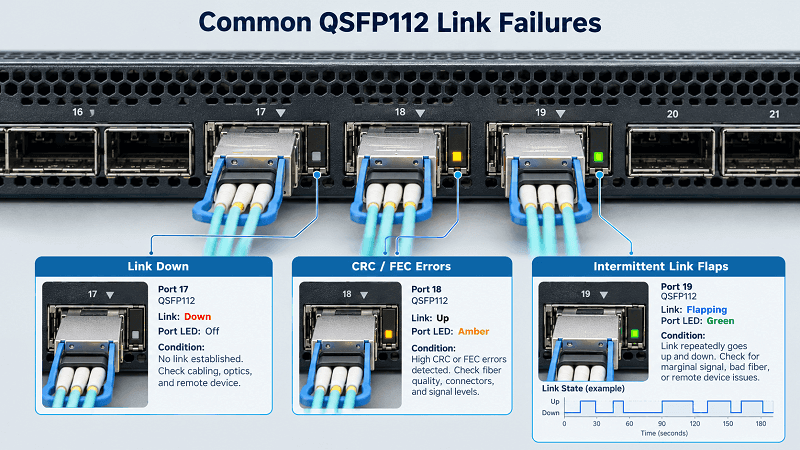
Most QSFP112 failures cluster into a few recognizable patterns. Find yours in the first column, then work the check that follows.
| Symptom | Most likely cause | First check |
| Link down, module detected | CMIS/EEPROM identity or cage power (a compatibility gate) | The DOM identity telltale below |
| Link down, module not detected | Seating, signal-detect, host speed config | Reseat, then confirm host speed and firmware |
| Link up, no traffic | FEC mismatch between the two ends | FEC status on both endpoints |
| Link up, CRC or symbol errors climbing | Physical: contamination, insertion loss, marginal budget | Clean, then read per-lane DOM |
| Intermittent flaps under load | FEC, thermal, or a marginal optical budget | FEC histogram and module temperature |
| Breakout, only some legs link | MPO polarity or lane mapping | Verify breakout programming |
| Port shuts down after warm-up | Thermal shadowing or insufficient airflow | Module temperature vs its neighbors |
Start at the top of the table and resist the urge to jump. An engineer who begins with cleaning wastes the most time on the cases that cleaning cannot touch.
Need known-good modules to swap in? FiberMall stocks 400G QSFP112 transceivers in SR4, DR4, FR4 and LR4 variants, plus LPO builds for lower power.
Why QSFP112 Fails Differently: Four Lanes at 112G
If you have already configured 400G links using QSFP-DD modules, you may be tempted to approach QSFP112 troubleshooting in exactly the same way. However, the electrical interfaces can differ significantly, creating different signal-integrity and compatibility requirements.
Four Lanes at 112G, Not Eight at 50G
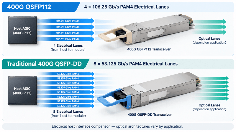
A typical 400G QSFP112 transceiver uses four electrical lanes operating at 106.25 Gb/s with PAM4 signaling, providing approximately 112G-class signaling per lane when referring to the interface generation. Traditional 400G QSFP-DD implementations commonly use eight electrical lanes operating at approximately 53.125 Gb/s.
QSFP-DD is a form factor rather than a fixed lane-speed specification, however, and newer QSFP-DD implementations may support higher electrical lane rates.
Using fewer, faster electrical lanes places greater demands on host signal integrity, equalization, channel insertion loss, and PAM4 signal quality. Forward error correction (FEC) is also critical in maintaining reliable operation for standard 400GbE applications.
The optical side must be evaluated separately. Optical lane architecture, reach, and link budget depend on the specific transceiver standard rather than the QSFP112 or QSFP-DD form factor alone.
For teams migrating from traditional QSFP-DD infrastructure, this distinction is important. A link that previously worked with one 400G transceiver type may not work with a different optical standard or electrical interface configuration. The failure may involve host compatibility, signal integrity, FEC configuration, or the optical link budget.
The fiber itself may remain unchanged, but the requirements of the new transceiver application must still be verified.
For additional background, see our QSFP-DD vs QSFP112 comparison, which explains the differences in electrical interfaces, form factors, and deployment considerations.
“Link Up” Does Not Mean “Link Healthy”
A QSFP112 link can report an operational state while experiencing an increasing number of corrected transmission errors.
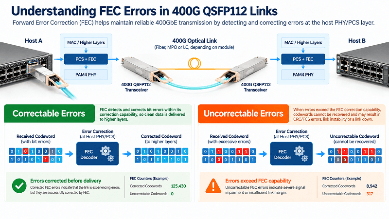
PAM4 signaling operates with smaller signal margins than NRZ at comparable symbol rates, making FEC an important part of high-speed Ethernet transmission. FEC can correct errors before they affect delivered traffic, so corrected-codeword counters may increase even when the link remains operational.
However, corrected FEC errors do not necessarily mean that user traffic is being corrupted. They indicate that errors have been detected and corrected within the capability of the FEC mechanism.
The situation becomes more serious when uncorrectable FEC errors appear, the pre-FEC bit error rate increases beyond acceptable limits, or the interface begins recording CRC/FCS errors and link instability.
Ethernet standards define specific conditions for loss of alignment and link failure, but those conditions depend on the applicable PCS and FEC implementation. They should not be reduced to one universal uncorrectable-codeword threshold for every QSFP112 application.
Read the error counters before trusting a green link indicator. A link with increasing corrected errors deserves attention, especially when the error rate approaches platform warning thresholds or is accompanied by uncorrectable errors.
The QSFP112 Field Workflow
Five steps, in order. Each step either resolves the fault or narrows the investigation to a specific part of the link.
Step 1: Capture State Before You Touch Anything
Record the module type, vendor, part number, serial number, firmware version, link state, per-lane DOM readings, FEC configuration, and interface error counters.
Where supported, capture the port’s link-training or initialization state and relevant system event logs.
This provides a baseline for comparing measurements before and after each troubleshooting action.
Without an initial record, engineers may change several variables at once and lose the ability to identify which action resolved the fault.
Do not clear counters or restart the interface before collecting the available diagnostic information.
Step 2: Physical Layer, Then Stop
Inspect both ends of the optical connection using appropriate fiber inspection equipment.
For MPO-12 connectors used by SR4, VR4, and DR4 modules, use a compatible MPO cleaning tool. Inspect the ferrule, fiber end faces, guide-pin configuration, and connector alignment.
For duplex LC connectors commonly used by FR4 and LR4 modules, use an LC-compatible cleaning tool or an approved fiber-cleaning procedure.
Inspect before cleaning whenever possible, then clean and inspect again to confirm that contamination has been removed. Follow the inspection criteria and procedures appropriate to the connector type. Never inspect an active fiber directly with an optical instrument that is not designed for safe use on live connections.
Next, reseat the transceiver according to the host manufacturer’s handling instructions and confirm that it is fully inserted and latched.
A partially inserted module or contaminated connector can cause intermittent optical faults, but cleaning and reseating should not be repeated indefinitely when diagnostic evidence points to a different failure category.
Connector contamination is a common physical-layer cause of optical link degradation. Dirt, oil, or damaged end faces can increase insertion loss and back-reflection, reducing the available optical margin.
If the physical connection is clean and properly seated, continue with telemetry and configuration checks rather than repeatedly replacing patch cords.
Step 3: Read the DOM/DDM Per Lane
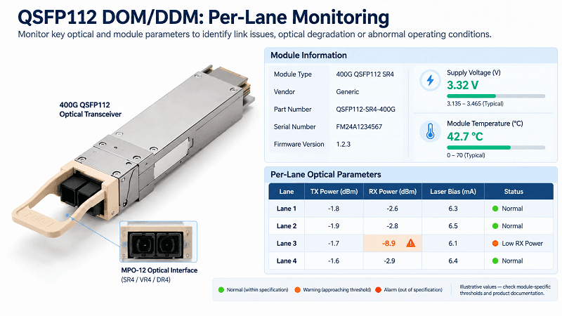
Digital optical monitoring helps identify optical, thermal, and power-related abnormalities. Read the available measurements for each optical lane rather than relying only on aggregated values.
Key parameters include:
- Supply voltage (Vcc): Compare the reported voltage with the module’s specified operating range and warning thresholds. For modules designed around a nominal 3.3 V supply, abnormal readings may indicate power delivery, management, or module issues.
- Temperature: Compare the reported module temperature with the manufacturer’s specified operating limits. Many commercial optical transceivers are rated for a 0–70°C case-temperature range, but the applicable limits and measurement locations depend on the product specification.
- Laser bias current: Track changes relative to the module’s historical baseline and manufacturer-defined thresholds. Sustained increases can indicate laser aging, temperature compensation, or other transmitter-related conditions, but should not be treated as a standalone failure indicator.
- TX and RX optical power per lane: Compare the transmitting optical power at endpoint A with the corresponding received power at endpoint B, accounting for the optical interface and lane mapping.
If TX power is within specification but RX power is below the receiver’s operating range, investigate the fiber path, connector condition, polarity, and optical loss budget.
An RX reading near -40 dBm may indicate loss of optical signal, a value below the measurement range, or unavailable telemetry. It does not automatically prove that the fiber is physically broken.
A consistently low RX reading may indicate excessive optical attenuation, while fluctuating power can suggest intermittent connectivity, a marginal optical path, or a transmitter issue.
For complete register definitions, consult our CMIS and DDM/EEPROM guide. In QSFP112 troubleshooting, per-lane measurements are particularly useful when isolating optical failures.
Step 4: Verify FEC on Both Ends
Check the FEC configuration and operational status on both endpoints.
For standard 400GbE QSFP112 applications, the required Ethernet FEC is generally implemented by the host platform. RS(544,514) is commonly used in 400GbE implementations, but the exact requirements depend on the applicable Ethernet application and host interface.
Read the available FEC counters, including corrected codewords, uncorrectable codewords, and error histograms.
Corrected errors indicate that FEC is operating, while increasing uncorrectable errors may indicate insufficient signal margin or a more serious physical-layer problem.
If the endpoints are configured incompatibly, verify the required FEC mode for the selected application and adjust the configuration according to the equipment manufacturer’s instructions.
Do not disable mandatory host FEC simply because the module contains internal signal processing.
Depending on the platform, a FEC configuration change may require an interface restart before taking effect. Record the original settings and perform disruptive changes within an approved maintenance window.
After applying the configuration, check the operational FEC state and repeat the error-counter measurements.
The detailed FEC requirements for different applications are covered in our QSFP112 compatibility guide. Here, the focus is identifying configuration mismatches and interpreting FEC-related errors.
Step 5: Swap, Loopback, Soak
If the fault remains unresolved, isolate the hardware components systematically.
Where safe and practical, substitute a known-good compatible module, then test the cable or fiber path, and finally try another supported host port.
Record whether the problem follows the module, remains associated with the cable, or stays on the original port.
If the fault follows a particular transceiver, the module or its compatibility with the host becomes a stronger suspect. If it remains on one host port despite known-good components, investigate the port hardware, configuration, and platform state.
Where supported, use optical or electrical loopback tests to isolate the transmit and receive paths. Ensure that the selected loopback method is compatible with the transceiver and platform.
Finally, perform a sustained traffic test under representative operating conditions.
A link that remains up for sixty seconds is not necessarily stable. Marginal high-speed links may exhibit errors during extended operation, changing temperatures, or sustained traffic.
Monitor FEC counters, CRC/FCS errors, temperature, and link-state transitions throughout the test.
Module Detected, No Link: The Identity Telltale
This is the case that eats engineering hours, and it is the one worth memorizing.
EEPROM, Not Optics
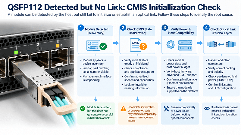
When a QSFP112 module is correctly inserted but fails to establish a link, inspect its CMIS identification and initialization information.
Potential warning signs include:
- The module compliance information is missing or reported as unspecified.
- The supported application or cable speed information appears as zero or is unavailable.
- The reported power class does not match the expected module specifications.
- Optical telemetry is unavailable or appears invalid.
- The module remains in an unexpected low-power or initialization state.
These readings may indicate incomplete initialization, management-interface communication problems, or host firmware incompatibility.
However, no single combination of unspecified compliance, zero reported speed, and a particular power-class reading should be treated as definitive proof that the host rejected the module.
For example, an unexpectedly reported 1.5 W power class may be a fallback or incorrectly interpreted identification value on some platforms, rather than the module’s actual maximum power requirement.
Similarly, Vcc readings near zero or RX power readings near -40 dBm may reflect unavailable telemetry, power problems, or a disabled transmitter.
The important distinction is that a module detected by the host is not necessarily fully initialized or ready to establish an optical link.
If module initialization has failed, cleaning connectors alone will not resolve the problem.
Route It to the Right Owner
Consider another illustrative scenario involving an engineer named Marcus troubleshooting a QSFP112 module on a ConnectX-7-based system.
After replacing several cables and transceivers, the link remains down. A closer examination of the module information reveals that the host is not correctly initializing the installed module.
Instead of continuing to replace optical components, the investigation shifts to platform compatibility and module management.
Possible causes include:
- Lack of support for the required 100G-class electrical interface
- Unsupported transceiver firmware or application
- Incompatible host firmware or driver versions
- CMIS implementation or management-interface issues
- Insufficient host power budget
- Incorrect module application selection
- Ethernet-versus-InfiniBand compatibility restrictions
QSFP112 module power requirements vary by design. Some modules operate within relatively low power budgets, while higher-power optical implementations may require additional host power and thermal support.
Always compare the module’s advertised power requirements with the host platform’s supported power budget. Insufficient power capability may prevent the module from entering the required operating state.
The detailed compatibility requirements, firmware considerations, and CMIS support information belong in our QSFP112 compatibility guide.
Use that guide to resolve compatibility issues, and use the diagnostic steps here to recognize when the fault is more likely related to module initialization than optical connectivity.
Fixing FEC Mismatch and CRC Errors
FEC configuration and physical-layer errors are important causes of unstable QSFP112 links. However, FEC configuration problems must be distinguished from errors that arise because the channel itself has insufficient signal margin.
The Mismatch Signatures
A FEC configuration problem can appear in several ways.
The link may remain down because the endpoints are configured for incompatible FEC modes, or the platform may report a configuration error or unsupported operating mode.
In some cases, the link may establish at the physical level but still exhibit traffic or error-counter abnormalities that require further investigation.
Fixed FEC settings on one endpoint and incompatible automatic or negotiated settings on the other can create problems on platforms that support multiple FEC configurations.
For standard 400GbE applications, both endpoints must operate according to compatible FEC requirements defined by the applicable Ethernet implementation.
Before changing settings, check the supported mode, operational FEC status, and platform documentation.
Do not assume that every link flap under load is caused by FEC mismatch. Thermal problems, optical attenuation, marginal electrical signal integrity, and port hardware faults can produce similar symptoms.
Understanding Host and Module-Level FEC
Some specialized high-speed optical transceivers incorporate internal DSP functions or additional signal-processing mechanisms.
However, these functions should not be confused with the mandatory Ethernet FEC implemented by the host in standard 400GbE applications.
Internal processing does not automatically conflict with host-side FEC, nor does it mean that two correction stages will introduce additional transmission errors.
In standard Ethernet implementations, the required FEC must remain enabled according to the applicable specification and equipment requirements.
The correct troubleshooting approach is to verify which FEC functions are implemented by the host, which functions are internal to the transceiver, and whether the selected operating mode is supported.
Do not disable host FEC as a general troubleshooting measure.
When CRC/FCS errors increase, investigate optical signal quality, electrical signal integrity, FEC counters, and configuration before attributing the problem to multiple correction stages.
Verify by Vendor
Read FEC status per platform, and always on both ends:
| Platform | Check FEC |
| NVIDIA (ConnectX / switch) | mlxlink –show_fec |
| Cisco NX-OS | show interface Ethernet1/1 fec |
| Arista EOS | show interfaces Ethernet1 status |
| Juniper Junos | show interfaces et-0/0/0 extensive |
| SONiC | show interfaces status |
Command syntax and available FEC diagnostics vary by hardware model, network operating system, and software version.
On some platforms, interface-status commands provide only a basic overview and do not expose detailed FEC counters.
If a configuration change does not appear in the operational state, verify whether the platform requires an interface restart. Then read the FEC statistics again.
Breakout and Thermal Faults
Two additional fault categories deserve special attention: partial breakout failures and thermal instability.
For breakout connections, the most obvious symptom is partial success. A 2×200G QSFP112 breakout may establish one link while the other remains down, or one breakout leg may experience intermittent errors.
Possible causes include incorrect breakout programming, lane mapping, remote-port configuration, cable compatibility, or optical connectivity.
For MPO-based parallel optical breakout links, fiber polarity and lane assignments are particularly important. Verify the selected polarity method, connector configuration, and mapping between the transmitting and receiving lanes.
Do not assume that every breakout failure is caused by a Method B crossover. The correct polarity arrangement depends on the specific cabling architecture and transceiver application.
For DAC, ACC, and AOC breakout assemblies, confirm that the cable and both endpoints support the intended breakout mode.
The detailed 2×200G and 4×100G configurations are covered in our QSFP112 breakout guide. Here, the objective is recognizing the symptoms and identifying the affected lane or breakout leg.
Thermal faults often become apparent after sustained operation.
A port that works when cold but becomes unstable after warming up may be experiencing excessive module temperature, insufficient airflow, or a platform-level thermal protection event.
Read the module temperature and compare it with neighboring ports, the product’s specified limits, and available environmental measurements.
In high-density or belly-to-belly cage configurations, temperature distribution depends on airflow direction, port placement, heatsink design, neighboring module power consumption, and chassis cooling.
Upper-row and lower-row modules may operate at different temperatures, but there is no universal temperature difference that applies to every QSFP112 host system.
Likewise, the maximum supported ambient temperature depends on the module and host thermal design rather than a fixed 25–30°C limit for all air-cooled installations.
Improve airflow, check fan operation, maintain appropriate rack cable management, and follow the equipment manufacturer’s thermal guidelines before replacing a suspected module.
Our QSFP112 power consumption and thermal guide explains the relevant power and cooling considerations. For high-density installations where air cooling is insufficient, compatible liquid-cooling QSFP112 solutions may provide an alternative, subject to the system’s mechanical and thermal requirements.
QSFP112 Diagnostic Command Reference
One command per platform answers most of the questions. The NVIDIA column is the richest for QSFP112, since mlxlink reads status, FEC, DOM and BER in one tool.
| Question | NVIDIA (mlxlink) | Cisco / Arista / Juniper |
| Is it healthy? | mlxlink -d <dev> (status + opcode) | show interface transceiver |
| FEC state | –show_fec | show interface … fec |
| FEC error histogram | –rx_fec_histogram –show_histogram | N/A on most platforms |
| BER / physical counters | -c or –show_counters | show interface … counters errors |
| Module DOM / DDM | –cable –ddm | show interface … transceiver details |
| Eye margin | –margin | N/A |
Treat the toolchain as a diagnostic aid, not a monitor. Run it when you have a symptom, then clear the counters and soak. The NVIDIA mlxlink documentation covers the full flag set, and the NVIDIA LinkX User Guide covers the QSFP112 cage rules and the ConnectX-7 handling of unsupported cables.
The QSFP112 Link-Down Checklist
Keep this sequence on hand for the next outage.
1. Capture state: module, DOM, counters. Change nothing yet.
2. Inspect, clean and reseat both connectors.
3. Read per-lane DOM and compare TX on one end to RX on the other.
4. Check for the identity telltale. If it is present, stop cleaning and fix the gate.
5. Verify FEC matches on both ends, then bounce the interface.
6. Swap the module, then the cable, then the port. Watch where the fault follows.
7. Run a sustained traffic soak and re-read the error counters.
8. If it is thermal, fix airflow before you reach for a replacement.
QSFP112 Troubleshooting FAQ
Why is my QSFP112 link down?
Common causes include connector contamination, incorrect cabling, loss of optical signal, FEC configuration problems, incomplete module initialization, host incompatibility, and power or thermal limitations. Capture the initial port state, inspect the physical connection, and review DOM and module-management information before making configuration changes.
Why does my QSFP112 module show as detected but not link?
A detected module is not necessarily fully initialized or operational. Check the CMIS state, module identity, supported applications, host power status, firmware compatibility, and optical telemetry.
Unspecified compliance information, zero reported speed, or unavailable DOM readings may indicate initialization or management problems, but they do not establish a definitive cause on their own.
What FEC does QSFP112 require?
Standard 400GbE QSFP112 implementations generally use RS(544,514) FEC according to the applicable Ethernet specification. However, the required FEC configuration depends on the supported host interface and application.
Both endpoints must operate with compatible FEC settings. Do not disable required FEC without verifying the relevant standard and equipment documentation.
How do I read QSFP112 DDM/DOM values?
Use supported module-management or vendor diagnostic tools to read supply voltage, temperature, laser bias current, and per-lane TX/RX optical power.
Compare the readings against the transceiver’s specifications and warning thresholds. Comparing the transmitter output at one endpoint with the receiver input at the other can help distinguish optical path loss from transmitter or receiver problems.
Why does my QSFP112 link flap under load?
Intermittent link flaps can result from marginal optical or electrical signal integrity, excessive temperature, power instability, faulty cabling, or incompatible configuration.
Read the FEC error counters, module temperature, optical power levels, and system event logs. A correlation between rising temperature and link failures may indicate a thermal problem, while increasing error rates can point to insufficient signal margin.
Can a dirty connector really bring down a 400G QSFP112 link?
Yes. Connector contamination can increase insertion loss, back-reflection, and optical signal degradation, potentially preventing the link from establishing or causing intermittent errors.
MPO connectors are especially important to inspect carefully because multiple fiber end faces must maintain proper alignment and cleanliness.
However, contamination is only one possible failure cause. If cleaning does not improve the diagnostic readings, continue investigating module initialization, compatibility, and signal integrity.
How do I diagnose QSFP112 on an NVIDIA ConnectX-7?
Use mlxlink on supported NVIDIA hardware to inspect link status, FEC configuration, error counters, and module telemetry.
Useful options include –show_fec for FEC information, –rx_fec_histogram –show_histogram for supported FEC histograms, -c for physical counters, and –cable –ddm for module monitoring information.
Available commands and diagnostic capabilities depend on the NVIDIA adapter, firmware, MFT version, and operating mode.
Conclusion
QSFP112 troubleshooting is a structured diagnostic process, not a process of guessing and replacing components.
Capture the initial state, inspect the physical layer, read per-lane DOM measurements, verify FEC and configuration on both endpoints, and use controlled component substitutions to isolate the fault.
One of the most useful distinctions is identifying when a detected module has not completed initialization. Missing compliance information, unavailable application data, or invalid telemetry can indicate a module-management or compatibility issue, but these symptoms must be confirmed through additional CMIS, power, and host diagnostics.
Two habits make troubleshooting more effective.
First, remember that 100G-class electrical lanes introduce more demanding signal-integrity requirements than traditional 50G-class electrical lanes. However, the optical link budget still depends on the selected transceiver standard, not the form factor alone.
Second, never rely on a green link indicator as the only measure of link health. Examine FEC counters, optical telemetry, and sustained traffic performance before declaring the connection stable.
When a transceiver is confirmed to be faulty or incompatible, replace it with a validated module that meets the host platform’s requirements.
FiberMall offers 400G QSFP112 transceivers for high-speed Ethernet interconnections, including SR4, DR4, FR4, and LR4 solutions. Selected QSFP112 LPO SR4 modules provide lower-power options for compatible hosts, with actual power consumption and operating requirements defined by the individual product specifications.
For short-reach applications, QSFP112 AOC assemblies and DAC/ACC cables can simplify connectivity and eliminate the need for separate pluggable optical transceivers and patch cords.
Contact FiberMall’s engineering team for assistance selecting a compatible QSFP112 solution or diagnosing a link issue based on your switch, NIC, cabling architecture, and operating requirements.
Related Products:
-
 QSFP112-400G-SR4 400G QSFP112 SR4 PAM4 850nm 100m MTP/MPO-12 OM3 FEC Optical Transceiver Module
$400.00
QSFP112-400G-SR4 400G QSFP112 SR4 PAM4 850nm 100m MTP/MPO-12 OM3 FEC Optical Transceiver Module
$400.00
-
QSFP112-400G-DR4 400G QSFP112 DR4 PAM4 1310nm 500m MTP/MPO-12 with KP4 FEC Optical Transceiver Module
$500.00
-
QSFP112-400G-FR1 4x100G QSFP112 FR1 PAM4 1310nm 2km MTP/MPO-12 SMF FEC Optical Transceiver Module
$800.00
-
QSFP112-400G-FR4 400G QSFP112 FR4 PAM4 CWDM 2km Duplex LC SMF FEC Optical Transceiver Module
$600.00
-
QSFP112-400G-LR4 400G QSFP112 LR4 PAM4 CWDM 10km Duplex LC SMF FEC Optical Transceiver Module
$1000.00
-
FiberMall QSFP112-400G-VR4 Compatible 400G QSFP112 VR4 PAM4 850nm 50m MTP/MPO-12 OM4 FEC Optical Transceiver Module
$385.00