In the OTN protocol, a variety of rate definitions appear. Beneath these rates are the underlying principles of the OTN protocol and some key principles.
FiberMall will begin with these rate definitions and reveal some of the principles of the OTN protocol.
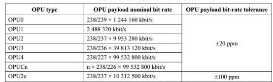
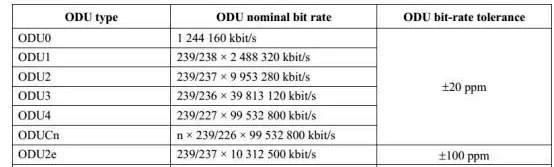
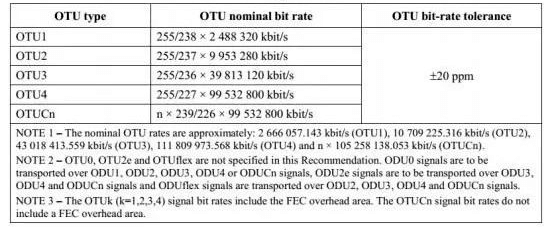
Rates of OTU, ODU, and OPU
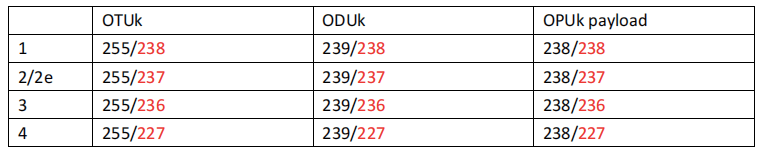
The OTU, ODU, and OPU rates for each level are shown below:
Here are a few tables from G.709, let’s look at the pattern.
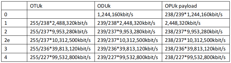
Rule 1: The ratio of OTUk, ODUk, and OPUk payload rates for the same level is OTUk:ODUk:OPUk = 255:239:238
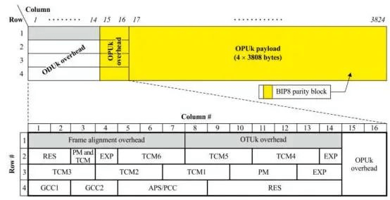
This is related to the frame structure definition of the OTU. The size of each frame of OTU is 4080 rows and 4 columns, of which the last 256 are listed as FEC, and the other parts (1~3824) are listed as ODU, so the ratio of OTUk and ODUk is 255:239.
Rule 2: The base rate of OTU1/OUT2/OTU3 is STM-16/STM-64/STM-256 respectively, and the base rate of OTU4 is 10x STM-64. The base rate of OTU2e is 10GE (10.3125G).
Among them, 2,488,320kbit/s, 9,953,280kbits/s and 39,813,120kbit/s are respectively the speed of STM-16/STM-64/STM-256. 99,532,800kbits/s is 10 times the rate of STM-64. By multiplying these baseline rates by a factor, you get the rates of OTU1/2/3/4. Visible OTU1/OTU2/OTU3 at the beginning of the design is to load SDH and consider. The base rate of the OTU2e, 10.3125G, is considered for carrying a 10GE signal.
Rule 3: 238/237/236/227
Factor law: OTU1/2/3/4 does not have the same ratio as the corresponding base rate, but has a factoring relationship of 238/237/236/227. The higher the rate level, the more padding there is in carrying STM to the same level of OTN.
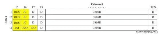
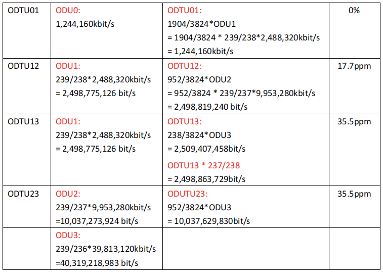
The rate of STM-16 is the same as that of the OPU1 payload. Therefore, the mapping between CBR2G5 and OPU1 is as follows, using all column 3804 data areas of the OPU1.
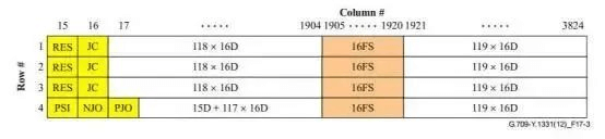
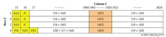
The speed of STM-64 is only 237/238 of the speed of the OPU2 payload. Therefore, the mapping between CBR10G and OPU2 is shown below, using only the 3788 column data region of OPU2, where columns 1905 to 1920 are fixed fill.
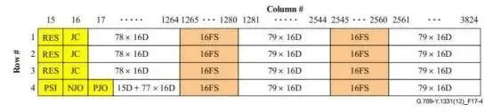
The STM-256 rate is only 236/238 of the OPU3 payload rate, so the CBR10G to OPU3 mapping is shown below, using only the 3772 columns of OPU3 data area, of which columns 1265 to 1980 and 2545 to 2560 are fixed padding.
The case of OTU2e is similar to OTU2, except that the load becomes a 10GE signal. Mapping 10GE to OPU2e is identical to mapping STM-64 to OPU2. CBR10G3 has a rate of 237/238 of OPU2e and uses only the 3788 column data area of OPU2e for the mapping, of which columns 1905 to 1920 are fixed padding:
Rule 4:
The rate of 2 ODU0 is equal to 1 OPU1: STM-4/2*2 = STM-4;
The rate of 4 ODU1 is slightly less than 1 OPU2: 239/238*STM-16*4 < 238/237*STM-64;
The rate of 4 ODU2 is slightly less than 1 OPU3: 239/237*STM-64*4 < 238/236*STM-256;
The rate of 10 ODU2 is slightly less than 1 OPU4: 239/237*STM-64*10 < 238/227*STM-64*10.
The rate of 10 ODU2e is slightly less than 1 OPU4: 239/237*10GE*10 < 238/227*STM-64*10.
This allows one OPU1 to carry 2 ODU0, one OPU2 to carry 4 ODU1, one OPU3 to carry 4 ODU2 or 16 ODU1, and one OPU4 to carry 10 ODU2 or 10 ODU2e, or 40 ODU1.
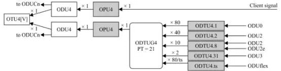
As shown below, for the mapping path of OTU4, 80 ODU0, 40 ODU1, 10 ODU2 or ODU2e, 2 ODU3 can be mapped to OPU4.
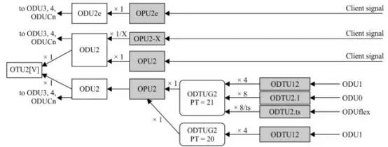
As shown below, for the mapping path of OTU2, 8 ODU0, 4 ODU1 can be mapped to OPU2.
As shown below, for the mapping path of OTU3, 32 ODUs0, 16 ODUs1, or 4 ODUs2 can be mapped to OPU3. And for the case of ODU2e, it is more special. Because the rate of OPU3 is smaller than the rate of 4 ODU2e, OPU3 cannot load 4 ODU2e, at most it can only load 3 ODU2e through the ODTU3.9 branch.
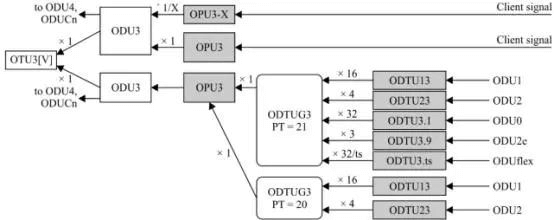
Rates of ODTU
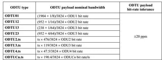
When the OPU carries low-rate class ODUs, the ODU needs to be adapted by ODTU (Optical Data Tributary Unit). ODTU contains an overhead part and a Payload part, the following are the bandwidths of various ODTU signal payloads.
There are two types of ODTU:
1) ODTU01, ODTU12, ODTU13, ODTU23 are one type (ODTUjk), referring to the tributary units that map the lower level ODUj to the higher level OPUk, using AMP mapping;
2) ODTU2.ts, ODTU3.ts, and ODTU4.ts is another type (ODTUk.ts), which refers to the tributary unit that uses ts high rate level OPUk, using GMP mapping.
In order to illustrate the rate law of ODTU more clearly, let’s first look at the process of mapping low-rate-level ODUs to high-rate-level OPUs.
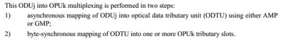
Step 1: ODUj can be mapped to ODTUjk by AMP mapping or to ODTUk.ts by GMP mapping.
Step 2: HO OPUk will be divided into many 1.25G/2.5G tributary slots, and ODTUjk or ODTUk.ts will be mapped into these 1.25G/2.5G tributary slots by byte synchronous mapping (simple time division multiplexing).
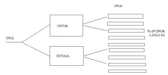
For example, mapping ODU2 into OPU3 is divided into two steps:
1) first map ODU2 to ODTU23, then map ODTU23 to OPU3
2) The rate of ODTU23 is about 10G, which needs to occupy 8 1.25G tributary slots, so you need to map ODTU23 to the 8 1.25G tributary slots of OPU3.
Another example is to map ODU2 to OPU4, which is divided into 2 steps:
1) first map ODU2 to ODTU4.8
2) The rate of ODTU4.8 is about 10G, which needs to occupy 8 1.25G tributary slots, so you need to map ODTU4.8 to the 8 1.25G tributary slots of OPU4.
It should be noted that the 1.25G tributaries of OPU2/OPU3/OPU4, although they are all called 1.25G tributaries, actually have different rates, with OPU2’s 1.25G tributary being the slowest at about 1.249Gbps and OPU4’s 1.25G tributary being the fastest at about 1.301Gbps.
Rule 5: The payload bandwidth formula of ODTUjk includes two parts: the integer and the mantissa.
1) Integer: OPUk can carry several ODTUjk, then the integer part is 3808 divided by it.
a) OPU1 can carry 2 ODTU01, the integer part 1904=3808/2
b) OPU2 can carry 4 ODTU12, the integer part 952=3808/4
c) OPU3 can carry 16 ODTU23, the integer part 238=3808/16
d) OPU3 can carry 4 ODTU13, the integer part 952=3808/4
2) Mantissa: OPUk can carry several ODTUjk, then the integer part is 1/4 divided by it.
a) OPU1 can carry 2 ODTU01, the fractional part 1/4/2 = 1/8
b) OPU2 can carry 4 ODTU12, the fractional part1/4/4 = 1/16
c) OPU3 can carry 16 ODTU13, the fractional part 1/4/16 = 1/64
d) OPU3 can carry 4 ODTU23, the fractional part 1/4/4 = 4/64
The mapping of ODTU to OPU is time division multiplexing, OPU is divided into multiple 1.25G/2.5G tributary slots (TS) and ODTU is mapped into these tributary slots, the mapping method is simple time division multiplexing.
When OPU1 carries 2 ODTU01, the load of each ODTU01 occupies 1/2 of the OPU1 load, so the load of ODTU01 should be half of the OPU1 load rate, i.e. 3808/2/3808*OPU1 load rate = 1904/3824*ODU1 load rate.
In addition, we need to take into account the NJO adjustment opportunity in the OPU1 overhead. Each OPU1 frame (4 lines) has only 1 byte of NJO adjustment opportunity, so for 2 ODTU01s, each ODTU01 needs two OPU1 frames to have 1 byte of NJO adjustment opportunity. After taking this adjustment opportunity into account, ODTU01 should also add 1/4/2 /3808* OPU1 load rate. This is the fractional part of the bandwidth calculation. It is a similar calculation for both OPU2/OPU3.
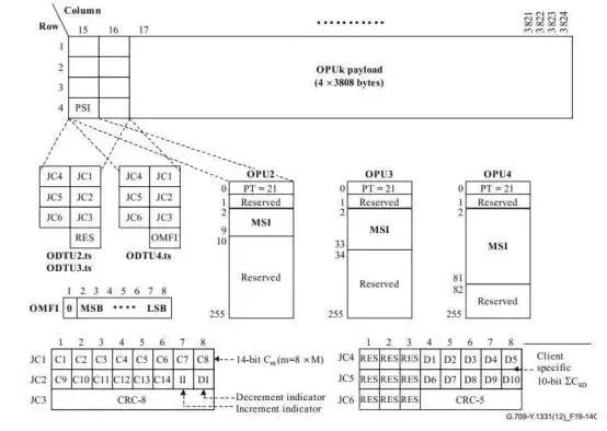
Rule 6: The payload rate of ODTUk.ts is proportional to the number of occupied tributary slots ts and proportional to the number of columns of 1.25G tributary slots in OPUk.
ODTUk.ts all use 1.25G tributary slots. ts indicates the number of occupied tributary slots, so the speed is of course proportional to ts. The more ts tributaries are needed, the higher the speed of ODTUk.ts. In different OPUk, the number of columns occupied by 1.25G tributary slots is different. the higher the speed level of OPUk, the less the number of columns occupied by 1.25G tributary slots. Therefore, the rate of ODUk.ts is proportional to the number of 1.25G tributary slots in OPUk when the rate of ODUk is used as the base.
In OPU2, there are 8 1.25G tributary slots, so the number of columns is 3808/8 = 476;
In OPU3, there are 32 1.25G tributary slots, so the number of columns is 3808/32= 119;
In OPU4, there are 80 1.25G tributary slots, so the number of columns is 3800/80 = 47.5 (where the rightmost 8 columns are filled);
ODTUk.ts does not use NJO adjustment opportunities, so its rate is not related to NJO and does not have a fractional part like ODTUjk.
How to Solve the Rate Difference
When the data is mapped to OPU (including the case that the customer side signal is directly mapped to OPU, and the low rate level ODU is mapped to the high rate level OPU, etc.), there is a certain difference between the data rate and the OPU load rate.
This difference may be due to the mismatch between the data rate and the OPU rate itself, or it may be caused by the inconsistency between the clock of data generation and the clock of OPU. The rate difference problem can be solved by a reasonable mapping method, and the OTN protocol specifies AMP, BMP, GMP, and GFP-F mapping methods.
AMP: Asynchronous Mapping Procedure
BMP: Bit-synchronous Mapping Procedure
GMP: Generic Mapping Procedure
GFP-F: Frame-mapped Generic Framing Procedure
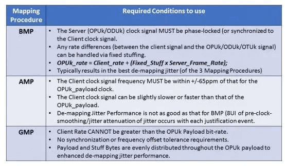
The differences between the use of BMP, AMP, and GMP mapping methods are shown in the table above.
BMP must have the Server clock and the Client clock completely homogeneous;
AMP mapping must have the Client signal clock frequency within 65 ppm of the OPUk’s load clock frequency
GMP must have a Client signal rate no greater than the load rate of OPUk.
There are two ways to map the signal to OPU, one is to map directly to OPU, and the other is to map to ODU and then map to OPU at a higher speed level. The following is the mapping type of ODUj to OPUk.
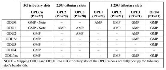
Rule 7: The mapping of PT=20 is 1.25G tributary mapping (except ODU0->OPU1); the mapping of PT=21 is 2.5G tributary mapping, and the mapping of PT=22 is 5G tributary mapping.
Mapping of ODU0:
ODU0 -> ODTU01 (AMP) -> OPU1 (PT=20)
ODU0 -> ODTU2.1 (GMP) -> OPU2 (PT=21)
ODU0 -> ODTU3.1 (GMP) -> OPU3 (PT=21)
ODU0 -> ODTU4.1 (GMP) -> OPU4 (PT=21)
Mapping of ODU1:
ODU1 -> ODTU12 (AMP)-> OPU2 (PT=20, PT=21)
ODU1 -> ODTU13 (AMP) -> OPU3 (PT=20, PT=21)
ODU1 -> ODTU4.2 (GMP) -> OPU4 (PT=21)
Mapping of ODU2:
ODU2-> ODTU23 (AMP) -> OPU3 (PT = 20, PT=21)
ODU2-> ODTU4.8(GMP) -> OPU4 (PT=21)
Mapping of ODU2e:
ODU2-> ODTU3.9 (GMP) -> OPU3 (PT=21)
ODU2-> ODTU4.8(GMP) -> OPU4 (PT=21)
Mapping of ODU3:
ODU3-> ODTU4.31 (GMP) -> OPU4 (PT=21)
We also list the cases where SDH and ETH client signals are directly mapped to OPUs as follows:
STM-16 -> OPU2 (AMP PT=02, BMP PT=03)
STM-64 -> OPU3 (AMP PT=02, BMP PT=03)
STM-256 -> OPU4(AMP PT = 02, BMP PT=03)
1000 BASE-X -> OPU0 (GMP PT=07)
10G BASE-R -> OPU2e (BMP, PT=07?)
40G BASE-R -> OPU3 (GMP PT = 07)
100G BASE-R-> OPU4 (GMP PT = 07)
Rule 8: The various customer signals are mapped as follows:
ODTU01, ODTU12, ODTU13, ODTU23 using AMP mapping;
ODTUk.ts uses GMP mapping;
SDH to the corresponding OTU using AMP or BMP mapping;
GMP mapping for Ethernet signals (except OTU2e);
10GE to OTU2e using BMP mapping.
Note that 10GE to OTU2e can only use BMP mapping, this is because the 10GE signal frequency deviation is 100ppm, AMP cannot support such a large clock jitter, so only BMP mapping can be used.
- BMP without rate difference
BMP mapping applies only when the rate of the Client signal is proportional to that of the Server signal. After a fractional frequency multiplication of the Client signal clock, it can be used as the clock of the Server signal; After the fractional frequency division in the recovery of the Server signal, it can be used as the clock of the Client signal.
BMP is used to map 10BASE-R to OPU2e. The STM signal to the corresponding OPUk can be mapped using either BMP or AMP.
- AMP resolves the rate difference
The AMP signal resolves the difference between the Client signal rate and the Server signal rate within a small range. There are two situations:
1) Frequency of Client signal and Server signal in a proportional relationship:
But because each uses its own local clock, errors in the clock itself can lead to differences in speed. For example, when STM-16 is loaded into OPU2 and OPU2 is sent with the local clock, the difference between the sent local clock and the STM-16 clock will cause an error in the rate ratio relation. This needs to be solved by the pointer adjustment method of the AMP map.
AMP mapping can resolve errors of +/-65ppm, input signal +/-45ppm, and OPU clock +/-20ppm. So where did this 65ppm figure come from? In fact, it is very simple: the payload area of OPUk is 3080*4 bytes. For each OPUk frame, there is a 1-byte positive adjustment opportunity PJO and a 1-byte negative adjustment opportunity NJO. Therefore, the maximum acceptable rate difference is +/-1 ÷ (3080*4) = +/-65.7ppm.
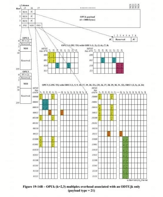
2) AMP mapping of ODTUjk:
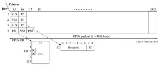
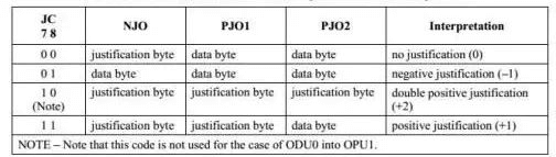
When ODUj is mapped to a 1.25G or 2.5G branch of OPUk via ODTUjk, ODTUjk has its own branch overhead TSOH to accommodate the rate difference between ODUj and ODTUjk. ODTUjk contains 1-byte negative tune-opportunity NJO and 2 bytes positive tune-opportunity PJO1 and PJO2. The methods of judging adjustment opportunities through JC are as follows:
Since each branch needs to use the overhead byte of OPUk, so the JC, NJO and so on of each branch slot are time multiplexed, that is, each branch slot uses the corresponding complex frame to indicate the OPUk overhead of the frame represented by MFAS. The same is true for PJOs, where the PJO overhead of two bytes per branch also uses the first and second column bytes indicated by the corresponding MFAS value. As shown in the picture below:
Then, the accepted range of rate difference for AMP mapping of ODTUjk is (-65ppm , +130ppm). The rate difference is calculated as follows:
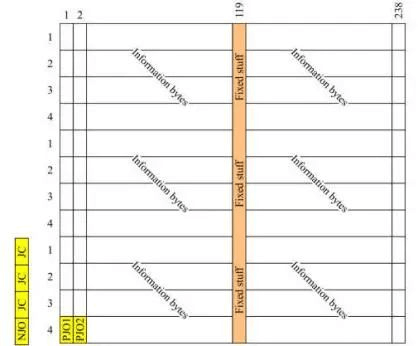
The following is the fixed padding of ODU1 mapped to ODTU13, there are 238 columns, and 119 columns are set as fixed padding.
When ODUjk is loaded, the rate difference ranges from 0 to 35.5ppm, the clock difference of input data is +/-20ppm, and the clock difference of output data is also +/-20ppm, so the rate difference of loading is -40ppm to 75.5ppm. A tuner of +/-65ppm for such a byte is obviously not enough. Therefore, ODUjk needs to use a 2-byte positive adjustment opportunity to make an acceptable rate difference of -65 PPM to 130ppm.
- GMP mapping solves greater rate differences
GMP mapping can address larger rate differences, requiring that the client-side signal must be smaller than OPUk’s load rate. GMP does not use NJO bytes. GMP uses the Sigma-Delta algorithm to intermittently mark certain data in the OPUk load as fixed fill and cannot be filled in the customer-side model, thus making the customer-side signal use the OPUk load rate.
OTUk.ts carrier mode: GMP mapping mode is used. At the same time, 1000BASE-X, 40GBASE-R, and 100GBASE-R are mapped to OPU0, OPU3, and OPU4 respectively in GMP mode.
Summary
FiberMall summarizes the various rate definitions in the OTN protocol and illustrates the principles implied by these rate definitions. This includes the OTN/ODU/OPU rates, the ODTU rates, and the pointer adjustment rules to resolve these rate differences.
Related Products:
-
 QSFP28-112G-SR4 112G OTU4 QSFP28 SR4 850nm 100m MTP/MPO MMF DDM Transceiver Module
$50.00
QSFP28-112G-SR4 112G OTU4 QSFP28 SR4 850nm 100m MTP/MPO MMF DDM Transceiver Module
$50.00
-
QSFP28-112G-LR4 112G OTU4 QSFP28 LR4 1310nm (LAN WDM) 10km LC SMF DDM Transceiver Module
$350.00
-
40G/100G OTU (OEO) Service Card, Transponder, 2 Channels, Supports Four 40G QSFP+ or 100G QSFP28, with 3R System
$900.00
-
XFP-CW10G53-40C 10G CWDM XFP 1530nm 40km LC SMF DDM Transceiver Module
$180.00
-
Juniper 100GBASE-ER4-D40 Compatible 100G QSFP28 Dual Rate ER4 1310nm (LAN WDM) 40km LC SMF DDM Transceiver Module
$1300.00
-
10G OTU(OEO) Card; Transponder, 3R Transparently Transmit 4 Channels' Service at Any Rate in 1G~11.3Gbps
$750.00
-
200G Muxponder Service Card: 20x10G SFP+ to 1x200G CFP2, 2 Slot
$8835.00
-
2x200G Muxponder Service Card: 4x100G QSFP28 to 2x200G CFP2, 1 Slot
$3285.00
-
200G Muxponder Service Card: 2x100G QSFP28 or 1x100G QSFP28 and 10x10G SFP+ to 1x200G CFP2, 2 Slot
$8835.00
-
2x400G Muxponder Service Card: 8x100G QSFP28 to 2x400G CFP2, 2 Slot
$4725.00
-
400G Muxponder Service Card: 4x100G QSFP28 to 1x400G CFP2, 1 Slot
$3285.00
-
DCI BOX Chassis, 19", 1U: 4 equal 1/4 slots, also compatible with 2 equal 1/2 slots, including front interface board, support provides 1 CONSOLE and 3 ETH management ports, 2 Standard CRPS power supplies: 220V AC or 48V DC optional
$3600.00