In the fast-evolving world of high-speed data transmission, OSFP (Octal Small Form-factor Pluggable) optical modules stand out as a cornerstone for next-generation networking. These modules are engineered to handle massive data rates, from 400G to 800G and beyond, making them essential for data centers, cloud computing, and AI-driven networks. But with great power comes great heat—literally. The thermal structure of OSFP modules is meticulously designed to manage heat dissipation, ensuring reliability, longevity, and optimal performance under demanding conditions.
At FiberMall, we specialize in providing cost-effective optical-communication products and solutions tailored for global data centers, cloud environments, enterprise networks, access networks, and wireless systems. As leaders in AI-enabled communication networks, we’re committed to delivering high-quality, value-driven OSFP optical modules that incorporate advanced thermal designs. If you’re exploring thermal-efficient solutions for your infrastructure, visit our official website or contact our customer support team for personalized guidance.
In this comprehensive guide, we’ll dive deep into the thermal structure of OSFP optical modules, exploring their design principles, key components, heat dissipation methods, and innovations. Whether you’re a network engineer, data center operator, or tech enthusiast, understanding these elements can help you make informed decisions for scalable, high-performance systems.
What Are OSFP Optical Modules?
Before delving into the thermal aspects, let’s set the stage with a brief overview of OSFP modules. OSFP is a pluggable transceiver form factor designed for high-speed Ethernet applications, supporting up to eight electrical lanes for aggregate data rates of 400Gbps or more. Unlike its predecessor QSFP-DD, OSFP offers a larger footprint, which allows for better thermal management and future-proofing for higher power consumption.
The OSFP Multi-Source Agreement (MSA) defines the mechanical, electrical, and thermal specifications to ensure interoperability across vendors. This standardization is crucial for widespread adoption in hyperscale data centers, where heat buildup can lead to system failures if not properly addressed.
Key features of OSFP modules include:
- High Data Rates: PAM4 modulation enables 400G, 800G, and even 1.6Tbps capabilities.
- Backward Compatibility: Adapters allow integration with existing QSFP systems.
- Power Efficiency: Designed to handle power levels up to 42.9W for advanced variants, necessitating robust thermal structures.
At FiberMall, our OSFP modules are built to these standards, offering seamless integration and superior thermal performance for AI-accelerated networks.
Why Thermal Management Matters in OSFP Modules
Thermal management is not just an afterthought—it’s a core design pillar for OSFP optical modules. As data rates soar, so does power consumption, leading to increased heat generation from components like lasers, DSP chips, and amplifiers. Poor heat dissipation can cause:
- Reduced module lifespan due to thermal stress.
- Performance throttling or failures in high-density deployments.
- Higher operational costs from inefficient cooling systems.
According to industry benchmarks, OSFP modules must operate reliably within temperature ranges from -40°C to 85°C, depending on the class (e.g., industrial or extended). Effective thermal design ensures that the module’s case temperature stays within safe limits, even under full load.
In data centers, where thousands of modules operate in confined spaces, airflow and heat transfer become critical. OSFP’s design addresses this by incorporating features that optimize airflow impedance and heat extraction, outperforming smaller form factors like QSFP-DD in thermal efficiency.
Key Components of OSFP Thermal Structure
The thermal structure of OSFP modules is a symphony of mechanical and material engineering. Let’s break down the primary components:
Heatsinks: The Frontline of Heat Dissipation
Heatsinks are integral to OSFP design, absorbing and radiating heat away from internal components. There are three main structural types, each with unique thermal implications:
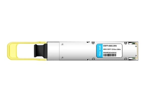
- Closed Top Heatsink: Features a solid upper surface for mechanical rigidity and EMI shielding. Airflow runs along the module’s length, with a smooth trailing edge to avoid interference. Ideal for standard power modules (up to 33W), it provides balanced cooling without excessive complexity.
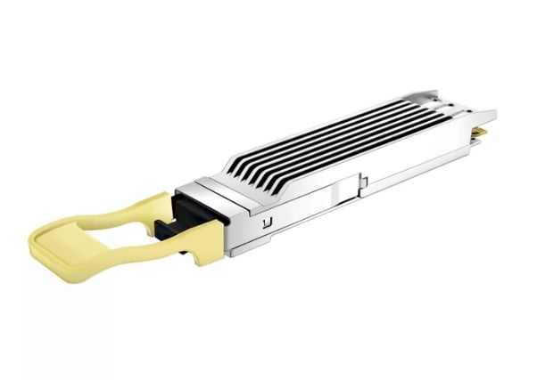
- Finned Top Heatsink (Open Top): Exposes fins on the top surface, creating additional airflow channels. This enhances dissipation for high-power applications (>33W), but requires precise dimensions to protect EMI fingers and maintain shielding. Fins are often arranged in gradient heights to reduce impedance and direct cooling air to hot spots.
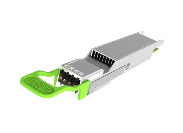
- Riding Heatsink (OSFP-RHS): Lacks an integrated heatsink, relying on an external one mounted on the cage. With a slim 9.5mm profile, it’s suited for advanced cooling like liquid systems in stacked configurations. This offers flexibility for ultra-high-density setups, with down force limited to 50N to prevent damage.
Materials like aluminum are commonly used for heatsinks due to their excellent thermal conductivity and lightweight properties. Surface flatness (0.05-0.15mm) and roughness (Ra 0.8-3.2µm) are specified to ensure optimal contact and heat transfer, especially for modules over 20W.
Cages and Ventilation Systems
OSFP cages house the module and facilitate airflow. Ventilation holes on the top, sides, rear, and bottom allow cooling air to pass through, preventing heat traps. For stacked cages (14.9mm or 19.9mm pitch), designs include cutouts for separate cooling devices like liquid cold plates.
In high-flow designs for OSFP1600, a 4.7mm groove directs external airflow to the connector area, supporting up to 42.9W power dissipation. This modular approach enhances thermal performance in dense racks.
Thermal Interface Materials (TIM) and Contact Pads
TIMs bridge the gap between hot components (e.g., DSP, laser drivers) and heatsinks, improving conductivity. High-quality TIMs reduce thermal resistance, while contact pads ensure even pressure distribution.
Heat Dissipation Methods in OSFP Design
Effective heat dissipation in OSFP modules relies on a combination of passive and active techniques, tuned to airflow dynamics.
Airflow Impedance Optimization
Airflow impedance is a key metric, measured at 20°C and sea level. For modules ≤33W, impedance curves ensure sufficient cooling under standard fan pressures. Higher-power modules (>33W) feature lower impedance designs to allow more airflow.
Innovations like gradient-height fin arrays reduce choking by channeling air to high-heat zones, lowering impedance by up to tens of percent compared to uniform fins. Strategic fin omissions further optimize flow without sacrificing surface area.
Passive and Hybrid Cooling
- Passive Methods: Rely on natural convection and conduction via heatsinks and cages.
- Hybrid Approaches: Combine with active elements like fans or liquid cooling. For instance, detachable riding heatsinks with thin aluminum covers (0.5-1mm) create controlled exhaust paths, preventing rear heat accumulation.
Two-phase immersion or drop-down heatsinks (e.g., Molex DDHS style) are emerging for 800G+ modules, handling extreme densities.
Testing and Compliance
Thermal performance is verified using MSA test jigs, ensuring modules meet impedance targets and touch temperature limits (per UL 62368-1 and NEBS GR-63). Automated testing equipment (ATE) simulates real-world conditions to validate endurance.
Innovations in OSFP Thermal Design
The field is ripe with innovations to tackle rising power demands:
- Gradient Fin Arrays: Tune airflow paths for efficiency, as seen in high-power deployments.
- Liquid Cooling Integration: Stacked cages with cutouts support cold plates, ideal for AI clusters.
- Optimized Packaging: Patents highlight electrical and thermal optimizations, reducing failure modes.
Comparisons show OSFP outperforming QSFP-DD in thermal margins due to its larger size and finned options. Flat-top designs with riding heatsinks are particularly effective for adapters like ConnectX-7.
At FiberMall, we incorporate these innovations into our OSFP lineup, ensuring modules excel in thermal efficiency for cost-sensitive applications.
How FiberMall Enhances OSFP Thermal Solutions
As a trusted provider, FiberMall’s OSFP optical modules feature state-of-the-art thermal structures, from finned-top designs for Quantum-2 switches to riding heatsink options for liquid-cooled systems. Our commitment to AI-enabled networks means we prioritize thermal reliability, helping clients reduce downtime and energy costs.
Whether you need 400G OSFP for enterprise networks or 800G for cloud interconnects, our solutions deliver value without compromise. Explore our catalog on the official website or reach out to our support team for custom consultations.
FAQ: Common Questions About OSFP Optical Modules’ Thermal Structure
To further assist you in understanding the thermal design of OSFP modules, we’ve compiled a list of frequently asked questions. These cover key aspects from basics to advanced considerations, helping network professionals and enthusiasts alike.
What is the primary purpose of thermal management in OSFP modules?
Thermal management in OSFP modules is essential to dissipate heat generated by high-power components like lasers and DSP chips. It prevents overheating, which can lead to performance degradation, reduced lifespan, or system failures. Effective designs ensure modules operate reliably in high-density data centers, maintaining optimal temperatures even at power levels up to 42.9W.
How does OSFP compare to QSFP-DD in terms of thermal efficiency?
OSFP modules generally offer superior thermal efficiency compared to QSFP-DD due to their larger footprint, which allows for more extensive heatsink designs and better airflow. This results in lower thermal resistance and higher power handling capabilities, making OSFP ideal for 800G+ applications where heat is a major concern.
What are the different types of heatsinks used in OSFP modules?
OSFP modules utilize three main heatsink types: closed top for standard power and EMI protection, finned top (open) for enhanced airflow in high-power scenarios, and riding heatsinks (OSFP-RHS) for external cooling flexibility in dense or liquid-cooled setups. Each type is optimized for specific power dissipation needs and airflow impedance.
Why is airflow impedance important in OSFP thermal design?
Airflow impedance measures how much resistance the module presents to cooling air. Lower impedance allows more efficient heat removal, crucial for high-power modules (>33W). Designs like gradient fin arrays minimize impedance, ensuring better cooling without increasing fan energy consumption.
Can OSFP modules support liquid cooling?
Yes, OSFP modules, especially those with riding heatsinks or stacked cage designs, are compatible with liquid cooling systems. Features like cutouts in cages allow integration with cold plates, making them suitable for ultra-high-density AI and cloud environments where air cooling alone may not suffice.
What materials are typically used in OSFP heatsinks and why?
Aluminum is the most common material for OSFP heatsinks due to its high thermal conductivity, low weight, and cost-effectiveness. Specifications for surface flatness and roughness ensure optimal contact with thermal interface materials, enhancing heat transfer efficiency.
How do I choose the right OSFP module for my thermal requirements?
Consider your application’s power consumption, density, and cooling infrastructure. For standard setups, closed top heatsinks suffice; for high-power or dense racks, opt for finned or riding heatsinks. At FiberMall, our experts can recommend tailored solutions based on your data center’s needs—contact us for a consultation.
Are there any standards for testing OSFP thermal performance?
Yes, the OSFP MSA outlines testing protocols using specialized jigs to measure airflow impedance and temperature compliance. Modules must adhere to safety standards like UL 62368-1 and NEBS GR-63 for touch temperatures and endurance under simulated real-world conditions.
What innovations are emerging in OSFP thermal structures?
Recent advancements include two-phase immersion cooling, drop-down heatsinks, and patented optimizations for electrical-thermal integration. These help handle escalating power demands in 1.6Tbps modules, with FiberMall incorporating such features for AI-driven networks.
Where can I purchase thermally efficient OSFP modules?
FiberMall offers a wide range of cost-effective OSFP modules with advanced thermal designs. Visit our official website to browse our catalog or reach out to customer support for personalized recommendations and pricing details.
Conclusion: Designing for a Cooler Future
The thermal structure of OSFP optical modules is a masterful blend of engineering, from heatsink types and ventilation systems to advanced airflow optimizations. By addressing heat at every level, OSFP ensures high-speed networks remain cool under pressure, paving the way for AI, 5G, and beyond.
Related Products:
-
 OSFP-800G-SR8D OSFP 8x100G SR8 PAM4 850nm 100m DOM Dual MPO-12 MMF Optical Transceiver Module
$650.00
OSFP-800G-SR8D OSFP 8x100G SR8 PAM4 850nm 100m DOM Dual MPO-12 MMF Optical Transceiver Module
$650.00
-
OSFP-800G-DR8D 800G-DR8 OSFP PAM4 1310nm 500m DOM Dual MTP/MPO-12 SMF Optical Transceiver Module
$850.00
-
OSFP-800G-2FR4L OSFP 2x400G FR4 PAM4 1310nm 2km DOM Dual Duplex LC SMF Optical Transceiver Module
$1200.00
-
OSFP-400G-LR4 400G LR4 OSFP PAM4 CWDM4 LC 10km SMF Optical Transceiver Module
$1199.00
-
OSFP-400G-DR4+ 400G OSFP DR4+ 1310nm MPO-12 2km SMF Optical Transceiver Module
$850.00
-
OSFP-2x200G-FR4 2x 200G OSFP FR4 PAM4 2x CWDM4 CS 2km SMF FEC Optical Transceiver Module
$1500.00
-
OSFP-400G-PSM8 400G PSM8 OSFP PAM4 1550nm MTP/MPO-16 300m SMF FEC Optical Transceiver Module
$1000.00
-
OSFP-400G-FR4 400G FR4 OSFP PAM4 CWDM4 2km LC SMF FEC Optical Transceiver Module
$900.00
-
OSFP-400G-DR4 400G OSFP DR4 PAM4 1310nm MTP/MPO-12 500m SMF FEC Optical Transceiver Module
$800.00
-
OSFP-400G-SR8 400G SR8 OSFP PAM4 850nm MTP/MPO-16 100m OM3 MMF FEC Optical Transceiver Module
$225.00