RoCE is known as RDMA over Converged Ethernet. So it is important to recognize RDMA as a technology before understanding RoCE.
What is RDMA?
In modern data centers, achieving high-speed, low-latency networking is critical for applications like artificial intelligence (AI), high-performance computing (HPC), and cloud storage. RoCE (RDMA over Converged Ethernet) is a cutting-edge protocol that delivers Remote Direct Memory Access (RDMA) capabilities over standard Ethernet networks, combining ultra-low latency with cost-effective infrastructure. This comprehensive guide dives into what RoCE is, how it works, its benefits, and its applications, empowering IT professionals to optimize their network performance. Whether you’re exploring RoCE for HPC clusters or enterprise storage, this article provides actionable insights to help you leverage this transformative technology.
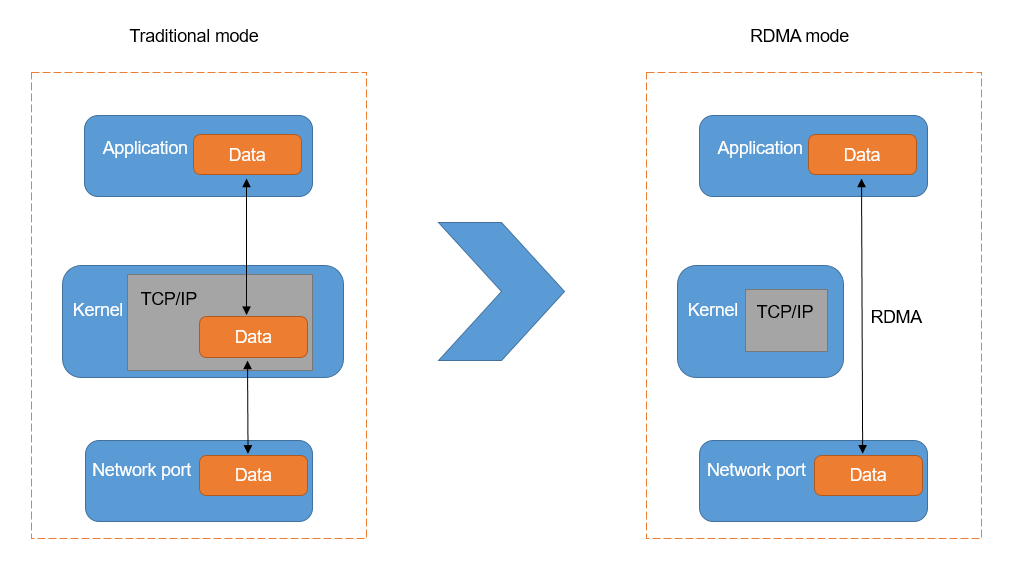
RDMA, Remote Direct Memory Access, can transmit data from one server to another, or from storage to server, with very minimal CPU occupancy. To send data, traditional applications have to go through the operating system to package TCP/IP, and then pass through the main cache, the NIC cache, and finally be sent out. This leads to two limitations.
Limitation 1: TCP/IP stack processing introduces a latency of several tens of microseconds. When the TCP protocol stack receives and sends messages, the kernel needs to do multiple context switches, each of which consumes 5-10 microseconds. Plus, at least three data copies and protocol work depend on the CPU. This means that just protocol processing will bring a fixed delay of several tens of microseconds. The delay of the protocol stack becomes the most obvious bottleneck.
Limitation 2: Processing with the TCP protocol stack results in a high load on the server CPU. In addition to the problem of a longer fixed delay, the TCP/IP network requires the host CPU to participate in the memory copy of the protocol multiple times. The larger the network size and the higher the network bandwidth, the greater the scheduling burden on the CPU when sending and receiving data, leading to a continuously high CPU load.
In data centers, if traditional TCP/IP is used for network interconnection among ultra-large scale distributed computing storage resources, it will consume a great deal of computing resources of the system, leading to IO bottlenecks and failing to meet the network demands for higher throughput and lower latency.
RDMA is a network interconnection technology that offers high bandwidth, low latency, and low CPU consumption. This technology overcomes many of the obstacles commonly associated with traditional TCP/IP networking.
Remote: Refers to data transferring between two nodes in a network.
Direct: No kernel involvement is required. All transmission processing is offloaded to the NIC (Network Interface Card) hardware.
Memory: The data are transferred directly between the virtual memory of the applications on both nodes, without the need for additional copying and caching.
Access: The access operations include send/receive, read/write, etc.
Compared with TCP/IP, RDMA reduces the usage of computing resources and increases the data transmission speed.
RDMA’s kernel bypass mechanism allows direct data read/write between the application and the NIC, reducing the data transfer latency within the server to nearly 1 microsecond. Also, RDMA’s zero-copy mechanism allows the receiving end to directly read data from the sender’s memory, significantly reducing the load on the CPU and improving CPU utilization.
The benefits of using RDMA include:
- Zero Copy: RDMA applications can bypass the kernel network stack and directly transfer data, eliminating the need to copy data from the user space memory of the application to the kernel network stack memory space.
- Kernel bypass: RDMA applications can initiate data transmission directly from user mode, avoiding the need for context switching between kernel mode and user mode.
- CPU offload: RDMA can directly access the memory of a remote host without consuming any CPU resources on the remote host. The remote host’s CPU can then focus on its prerogatives, avoid cache disturbance, and prevent a large-scale memory access data overspill.
What is RoCE?
Starting from 2010, RDMA caught more and more attention when the IBTA released the first specification for running RDMA over Converged Ethernet (RoCE). However, the initial specification limited the deployment of RoCE to a single Layer 2 domain because RoCE encapsulated frames lacked routing capabilities. In 2014, the IBTA released RoCEv2, which updated the initial RoCE specification to support routing across Layer 3 networks, making it more suitable for large-scale data center networks and enterprise data centers.
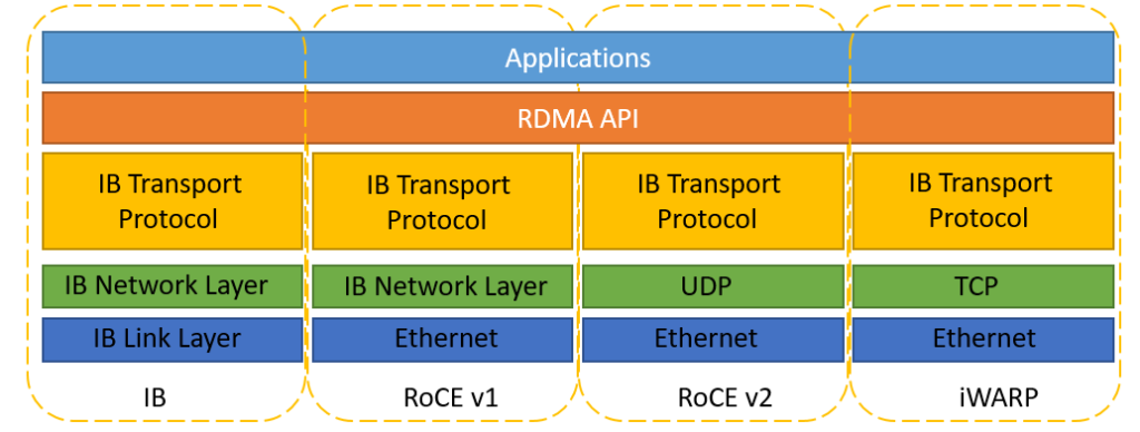
RDMA protocols include Infiniband (IB), Internet Wide Area RDMA Protocol (iWARP), and RDMA over Converged Ethernet (RoCE):
- InfiniBand: Designed with RDMA in mind, it re-designed the physical link layer, network layer, and transport layer, to ensure reliable transmission at the hardware level, and provide higher bandwidth and lower latency. But it is expensive and requires IB network cards and switches.
- iWARP: RDMA network based on TCP, using TCP to achieve reliable transmission. Compared with RoCE, in the case of large-scale networking, iWARP’s large number of TCP connections will consume a lot of memory resources, and require higher system specifications. It can use ordinary Ethernet switches, but it requires network cards that support iWARP.
- RoCE: RDMA is based on Ethernet, RoCEv1 version is based on the network link layer, cannot cross network segments, and has basically no application. RoCEv2 is based on UDP, can cross network segments has good scalability, and can achieve good throughput and latency performance, so it is the solution adopted on a large scale. RoCE consumes fewer resources than iWARP and supports more features than iWARP. It can use ordinary Ethernet switches but requires network cards supporting RoCE.
How Does RoCE Work?
RoCE leverages RDMA to enable direct memory access between networked devices, minimizing CPU overhead and latency. Here’s a simplified breakdown of its operation:
Memory Registration: Applications register memory regions for RDMA, allowing direct access by the network adapter.
Queue Pair Creation: RoCE uses queue pairs (send and receive queues) to manage data transfers, handled by RDMA-capable network interface cards (RNICs).
Data Transfer: The RNIC transfers data directly from the sender’s memory to the receiver’s memory, bypassing the CPU and kernel.
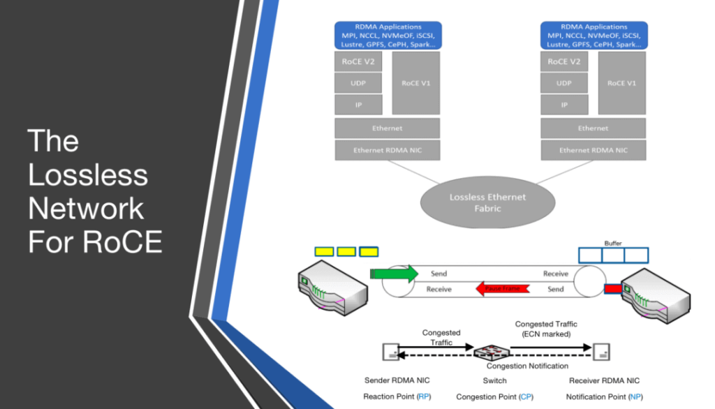
Lossless Ethernet: RoCE requires a lossless Ethernet network, achieved through PFC (for RoCE v1/v2) and ECN (for RoCE v2), to prevent packet loss and ensure reliable delivery.
For RoCE v2, IP-based routing and UDP encapsulation allow data to traverse complex networks, making it suitable for enterprise and cloud environments. This efficiency makes RoCE a game-changer for applications requiring high-speed data transfers.
Applications of RoCE
RoCE is widely adopted across industries requiring high-performance networking. Key applications include:
High-Performance Computing (HPC): RoCE enables low-latency communication in HPC clusters, supporting simulations in fields like physics, chemistry, and weather modeling.
Artificial Intelligence and Machine Learning: AI workloads demand massive data transfers. RoCE accelerates training and inference by minimizing latency and maximizing bandwidth.
Enterprise Storage: RoCE enhances storage solutions like NVMe-oF (NVMe over Fabrics), providing fast access to distributed storage systems.
Cloud Computing: Cloud providers use RoCE to optimize virtualized environments, ensuring high-speed data delivery for SaaS and IaaS platforms.
Financial Services: High-frequency trading platforms leverage RoCE’s ultra-low latency to execute trades faster, gaining a competitive edge.
RoCE vs. InfiniBand and iWARP
When choosing an RDMA protocol, understanding RoCE’s differences from InfiniBand and iWARP is critical. Here’s a comparison:
| Feature | RoCE | InfiniBand | iWARP |
| Network Type | Ethernet (v1/v2) | Proprietary fabric | Ethernet (TCP-based) |
| Latency | Sub-microsecond (<1 µs) | Sub-microsecond (<1 µs) | 3-5 µs |
| Bandwidth | Up to 400 Gbps | Up to 400 Gbps | Up to 100 Gbps |
| Cost | Moderate (uses Ethernet) | Higher (specialized hardware) | Moderate (Ethernet-based) |
| Scalability | High (RoCE v2 routable) | Very high (fabric topology) | Moderate (TCP overhead) |
| Lossless Requirement | Yes (PFC, ECN) | Built-in lossless fabric | No (uses TCP) |
RoCE offers a cost-effective RDMA solution over Ethernet, balancing performance and compatibility. InfiniBand excels in dedicated HPC environments, while iWARP suits TCP-based networks but sacrifices latency. For organizations with Ethernet infrastructure, RoCE is often the optimal choice.
Challenges and Considerations for RoCE
While RoCE offers significant advantages, it comes with challenges that require careful consideration:
Lossless Network Requirement: RoCE demands a lossless Ethernet environment, necessitating switches with PFC and ECN support, which can increase complexity.
Configuration Complexity: Properly tuning QoS and RDMA settings requires expertise to avoid performance issues.
Compatibility: Not all Ethernet switches support RoCE, so hardware upgrades may be needed.
Network Congestion: In large-scale deployments, improper congestion management can degrade RoCE performance.
Cost vs. Benefit: While cheaper than InfiniBand, RoCE-capable hardware may still require significant investment.
Mitigate these challenges by partnering with trusted vendors like Fibermall, which offers RoCE-compatible solutions and technical support.
Why is RoCE the mainstream RDMA protocol?
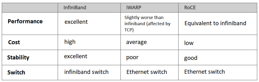
First, let’s talk about iWARP. The iWARP protocol stack is more complex than the other two, and because of the limitations of TCP, it can only support reliable transmission. Therefore, iWARP’s development is not as good as RoCE and Infiniband.
The Infiniband protocol itself defines a new set of hierarchical architecture, from the link layer to the transport layer, which is incompatible with existing Ethernet devices. For example, if a data center wants to switch from Ethernet to Infiniband technology because of performance bottlenecks, it must purchase a full set of Infiniband devices, including network cards, cables, switches, routers, etc., which is too costly.
The advantage of the RoCE protocol is very obvious here. Users only need to buy network cards that support RoCE to switch from Ethernet to RoCE, and other network devices are compatible. Therefore, RoCE’s main advantage over Infiniband is its lower cost.
RoCEv1
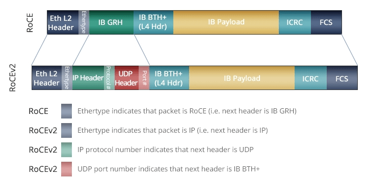
In April 2010, IBTA released RoCE, which was published as an addendum to the Infiniband Architecture Specification, so it is also called IBoE (InfiniBand over Ethernet). At this time, the RoCE standard used the IB network layer instead of the TCP/IP network layer on top of the Ethernet link layer, so it did not support the IP routing function. The RoCE V1 protocol has a typeID of 0x8915 at the Ethernet layer.
In RoCE, the Infiniband link layer protocol header is removed, and the GUID used to indicate the address is converted to Ethernet MAC. Infiniband relies on lossless physical transmission, and RoCE also relies on lossless Ethernet transmission, which brings cost and management overhead to the deployment of Ethernet.
The lossless transmission of Ethernet must rely on L2 QoS support, such as PFC (Priority Flow Control). When the buffer pool exceeds the threshold, the receiver sends a pause frame to the sender. After receiving the pause frame, the MAC layer of the sender automatically reduces the transmission rate. This requirement means that all nodes on the entire transmission link, including the end, switch, and router, must all support L2 QoS, otherwise the PFC on the link cannot play an effective role at both ends.
RoCEv2
Since the data frame of RoCEv1 does not have an IP header, it can only communicate within the L2 subnet. To solve this problem, IBTA proposed RoCE V2 in 2014, which extended RoCEv1, replacing the GRH (Global Routing Header) with UDP header + IP header. The extended frame structure is shown in the following figure. For RoCE v1 and RoCE v2, the following two points are worth noting:
- RoCE v1 (Layer 2) operates on the Ehternet Link Layer (Layer 2), so Ethertype 0x8915, so the normal Frame size is 1500 bytes, and Jumbo Frame is 9000 bytes.
- RoCE v2 (Layer 3) operates on UDP/IPv4 or UDP/IPv6 (Layer 3) and uses UDP Port 4791 for transmission. Because the RoCE v2 packet can be routed on Layer 3, it is sometimes called Routable RoCE or simply RRoCE.
Since RDMA requires a packet lossless network to avoid drastic performance degradation, RoCE technology needs to transform the traditional Ethernet network into a lossless Ethernet network using PFC, ECN, and DCQCN technologies, to ensure zero packet loss.
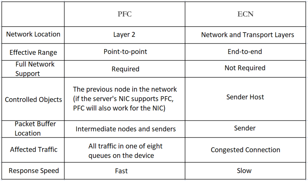
PFC: Priority-based Flow Control. PFC provides per-hop priority-based flow control for various types of traffic.
When forwarding packets, the device assigns packets to queues for scheduling and forwarding by looking up the priority of the packets in the priority mapping table. When the sending rate of 802.1p priority packets exceeds the receiving rate and the data buffer space at the receiver is insufficient, the receiver sends a PFC pause frame to the sender. When the sender receives the PFC pause frame, the sender stops sending packets with the specified 802.1p priority until the sender receives a PFC XON frame or the aging timer times out. When configuring PFC, the congestion of a specific type of packet does not affect the normal forwarding of other types of packets.
ECN: Explicit Congestion Notification. ECN defines a traffic control and end-to-end congestion notification mechanism based on the IP layer and the transport layer. When the device is congested, ECN marks the ECN field in the IP header of the packet. The receiver sends a congestion notification packet (CNP) to notify the sender to slow down the sending speed. ECN implements end-to-end congestion management, reducing the spread and aggravation of congestion.
DCQCN (Data Center Quantized Congestion Notification): Currently the most widely used congestion control algorithm in RoCEv2 networks. It merges QCN and DCTCP algorithms and requires data center switches to support WRED and ECN. DCQCN can provide better fairness, achieve a high bandwidth utilization rate, ensure a low queue buffer occupancy rate, and less queue buffer jitter.
At present, many manufacturers have their own lossless network solutions.
Huawei
Huawei’s iLossless intelligent lossless algorithm solution is an AI algorithm that utilizes artificial intelligence to achieve network congestion scheduling and network self-optimization. It’s centered on Automatic ECN and introduces Deep Reinforcement Learning (DRL) into ultra-high-speed data center switches. Based on the iLossless intelligent lossless algorithm, Huawei released the super-converged data center network solution CloudFabric 3.0, leading the intelligent lossless era into 1.0.
In 2022, Huawei’s hyper-converged data center network proposed intelligent lossless web calculation integration technology and innovative direct connection topology architecture, which can realize a 270k large-scale computational hub network. The delay can be further reduced by 25% based on intelligent lossless 1.0.
Huawei Intelligent Lossless 2.0 is based on in-network computing and topology-aware computing to achieve network and computing synergy. The network participates in the collection and synchronization of computing information, reducing the number of times of computing information synchronization. Simultaneously, it ensures the completion of computing tasks near the computing nodes through scheduling, reducing communication jumps, and further reducing application latency.
H3C
H3C’s AI ECN intelligent lossless algorithm, which draws on the network traffic model (Incast values, maximum queue depth, proportion of large and small flows, among other traffic characteristics in the N-to-1 model), utilizes reinforcement learning algorithms to train the AI with the traffic model. The AI can sense and predict network traffic trends in real time, and automatically adjust the most optimal ECN threshold for precise queue scheduling. In doing so, it balances the transmission of latency-sensitive small flows and throughput-sensitive larger flows to ensure optimal network performance, all while avoiding the triggering of network PFC congestion control.
H3C’s AD-DC SeerFabric lossless network solution is based on an edge-cloud AI collaborative architecture. By innovating and optimizing the industry’s AI ECN tuning algorithm and combining the local AI Inside capability of H3C’s data center switch, this solution boosts throughput and decreases latency while ensuring zero packet loss. It ensures precise network service quality and forwarding. Moreover, through fine-grained intelligent operations and maintenance, it visualizes the service experience of RoCE networks.
Inspur
In April 2022, Inspur Networks launched its typical lossless Ethernet solution, centered around data center Ethernet switches supporting the RoCE technology. The solution offers the following advantages:
1. Seamless integration of computing, storage, networking, and AIStation. It supports congestion management technologies such as PFC and ECN, allowing the establishment of end-to-end, lossless, low-latency RDMA-bearing networks. The switch’s excellent buffer advantage can absorb burst traffic smoothly, effectively dealing with TCP in cast scenarios.
2. Proactive fault discovery and automatic failover. RoCE-SAN networks can collaborate with storage operations for quick fault sensing. The switch can rapidly detect fault states and notify servers subscribing to notification messages within the relevant business domain, enabling a quick switch to redundant pathways and reducing business impacts. For large-scale, lossless Ethernet environments experiencing PFC deadlock issues, the solution provides a chip-level PFC deadlock prevention mechanism for automatic deadlock detection and recovery.
3. Plug-and-play storage. RoCE-SAN networks can automatically detect the incorporation of device servers and storage devices, notifying servers to automatically establish connections with the storage devices.
Related Products:
-
 Intel® 82599EN SR1 Single Port 10 Gigabit SFP+ PCI Express x8 Ethernet Network Interface Card PCIe v2.0
$115.00
Intel® 82599EN SR1 Single Port 10 Gigabit SFP+ PCI Express x8 Ethernet Network Interface Card PCIe v2.0
$115.00
-
Intel® 82599ES SR2 Dual Port 10 Gigabit SFP+ PCI Express x8 Ethernet Network Interface Card PCIe v2.0
$159.00
-
Intel® X710-BM2 DA2 Dual Port 10 Gigabit SFP+ PCI Express x8 Ethernet Network Interface Card PCIe v3.0
$179.00
-
Intel® XL710-BM1 DA4 Quad Port 10 Gigabit SFP+ PCI Express x8 Ethernet Network Interface Card PCIe v3.0
$309.00
-
NVIDIA (Mellanox) MCX621102AN-ADAT SmartNIC ConnectX®-6 Dx Ethernet Network Interface Card, 1/10/25GbE Dual-Port SFP28, Gen 4.0 x8, Tall&Short Bracket
$315.00
-
NVIDIA (Mellanox) MCX631102AN-ADAT SmartNIC ConnectX®-6 Lx Ethernet Network Interface Card, 1/10/25GbE Dual-Port SFP28, Gen 4.0 x8, Tall&Short Bracket
$385.00
-
Intel® E810-XXVDA4 25G Ethernet Network Adapter PCI Express v4.0 x16 Quad-port SFP28
$495.00
-
Intel® E810-XXVDA2 25G Ethernet Network Adapter PCI Express v4.0 X8 Dual-port SFP28
$209.00
-
Intel® XL710-BM1 QDA1 Single Port 40 Gigabit QSFP+ PCI Express x8 Ethernet Network Interface Card PCIe v3.0
$309.00
-
Intel® XL710 QDA2 Dual Port 40 Gigabit QSFP+ PCI Express x8 Ethernet Network Interface Card PCIe v3.0
$359.00
-
NVIDIA NVIDIA(Mellanox) MCX653105A-ECAT-SP ConnectX-6 InfiniBand/VPI Adapter Card, HDR100/EDR/100G, Single-Port QSFP56, PCIe3.0/4.0 x16, Tall bracket
$965.00
-
NVIDIA NVIDIA(Mellanox) MCX653106A-ECAT-SP ConnectX-6 InfiniBand/VPI Adapter Card, HDR100/EDR/100G, Dual-Port QSFP56, PCIe3.0/4.0 x16, Tall Bracket
$828.00
-
Intel® E810-CQDA2 100G Ethernet Network Adapter PCIe v4.0 x16 Dual port QSFP28
$589.00
-
Intel® E810-CQDA1 100G Ethernet Network Adapter PCIe v4.0 x16 Single port QSFP28
$409.00
-
NVIDIA NVIDIA(Mellanox) MCX653105A-HDAT-SP ConnectX-6 InfiniBand/VPI Adapter Card, HDR/200GbE, Single-Port QSFP56, PCIe3.0/4.0 x16, Tall Bracket
$1400.00
-
NVIDIA NVIDIA(Mellanox) MCX653106A-HDAT-SP ConnectX-6 InfiniBand/VPI Adapter Card, HDR/200GbE, Dual-Port QSFP56, PCIe3.0/4.0 x16, Tall Bracket
$1600.00