Data Center Network Architecture
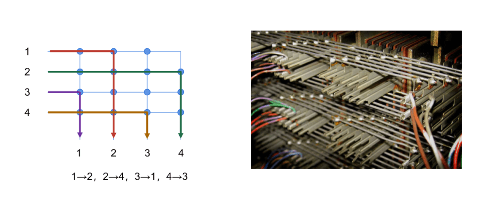
Crossbar architecture
- A type of architecture derived from the earliest telephone switching network (crossbar switch)
- Consists of multiple input ports, multiple output ports, and a switch matrix
- Very flexible and efficient, can achieve arbitrary connections between different devices.
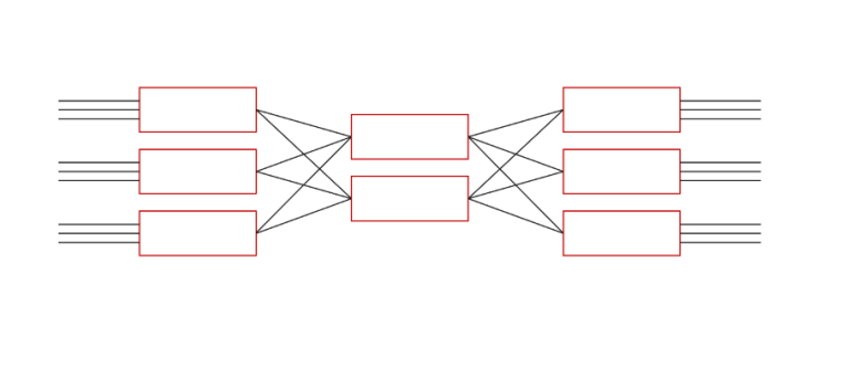
Clos architecture
- Born in 1952, proposed by a person named Charles Clos.
- Clos architecture mainly describes the structure of a multi-stage circuit switching network
- Clos architecture is an improvement of the crossbar structure, which can provide a non-blocking network. The advantage of Clos is that it saves costs and increases efficiency.
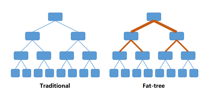
Fat-Tree architecture
A Fat-Tree is a type of CLOS network architecture.
Compared to the traditional tree structure, a Fat-Tree is more like a real tree, with thicker branches near the root. From the leaves to the root, the network bandwidth does not converge.
The basic idea: use a large number of low-performance switches to build a large-scale non-blocking network. For any communication pattern, there is always a path that allows them to achieve the bandwidth of the network card.
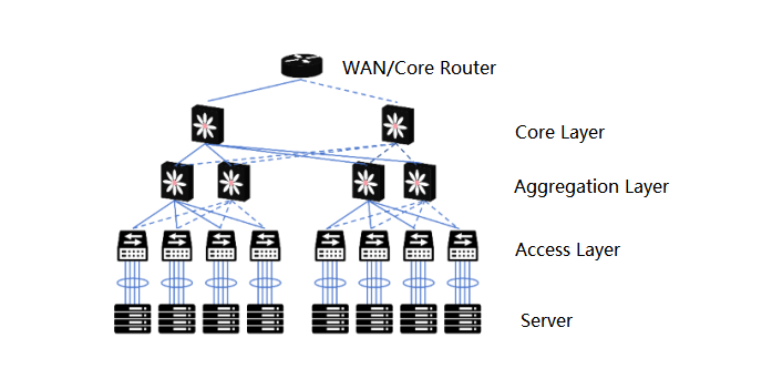
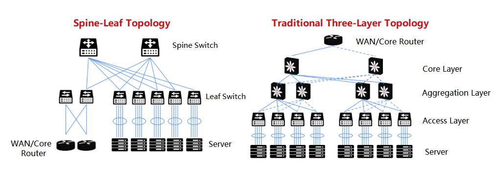
After the Fat-Tree architecture was introduced to the data center, the data center became a traditional three-layer structure:
Access layer: used to connect all the computing nodes. Usually in the form of a rack switch (TOR, Top of Rack).
Aggregation layer: used for interconnection of the access layer, and as the boundary of the second and third layers of the aggregation area. Various services such as firewalls, load balancing, etc. are also deployed here.
Core layer: used for interconnection of the aggregation layer, and to implement the third-layer communication between the entire data center and the external network.
The disadvantages of the Fat-Tree architecture:
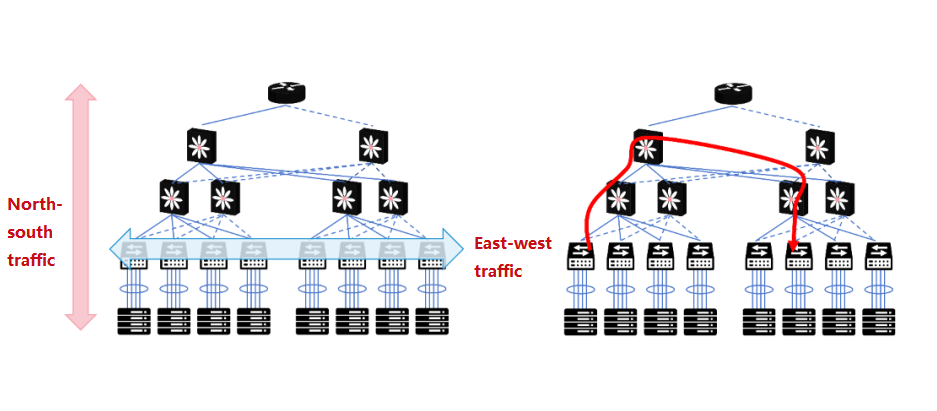
Resource waste: In the traditional three-layer structure, a lower-layer switch will be connected to two upper-layer switches through two links. Because the STP protocol (Spanning Tree Protocol) is used, only one link actually carries the traffic. The other uplink is blocked (only used for backup). This causes bandwidth waste.
Large fault domain: The STP protocol, due to its own algorithm, needs to reconverge when the network topology changes, which can easily cause faults and affect the network of the entire VLAN.
Not suitable for east-west traffic: The communication between servers and servers requires passing through the access switch, the aggregation switch, and the core switch.
Spine-Leaf network
Like the Fat-Tree structure, it belongs to the CLOS network model.
Compared to the traditional three-layer network architecture, the Spine-Leaf network has been flattened and turned into a two-layer architecture.
Leaf switch, equivalent to the access switch in the traditional three-layer architecture, as TOR (Top Of Rack) directly connected to the physical server. Above the leaf switch is the third layer network, each is an independent L2 broadcast domain. If the servers under two leaf switches need to communicate, they need to be forwarded by the spine switch.
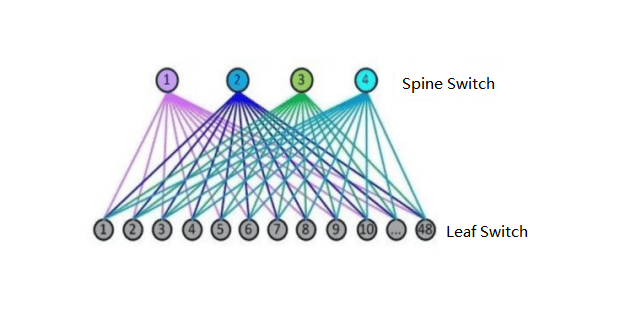
Spine switch, equivalent to the core switch. The leaf and spine switches dynamically select multiple paths through ECMP (Equal Cost Multi Path).
The number of downlink ports of the spine switch determines the number of leaf switches. The number of uplink ports of the leaf switch determines the number of spine switches. They jointly determine the scale of the Spine-Leaf network.
The Advantages of Spine-Leaf Network
High bandwidth utilization
Each leaf switch’s uplink works in a load-balancing manner, making full use of the bandwidth.
Predictable network latency
In the above model, the number of communication paths between leaf switches can be determined, and only one spine switch is required for each path. The east-west network latency is predictable.
Good scalability
When the bandwidth is insufficient, the number of spine switches can be increased to scale the bandwidth horizontally. When the number of servers increases, the number of spine switches can also be increased to expand the data center scale. Planning and expansion are very convenient.
Reduced requirements for switches
North-south traffic can go out from the leaf nodes or the spine nodes. East-west traffic is distributed on multiple paths. Expensive high-performance high-bandwidth switches are not required.
High security and availability
Traditional networks use STP protocol, which will reconverge when a device fails, affecting network performance or even causing faults. In the Spine-Leaf architecture, when a device fails, there is no need to reconverge, and the traffic continues to pass through other normal paths. The network connectivity is not affected, and the bandwidth is only reduced by the bandwidth of one path. The performance impact is negligible.
InfiniBand
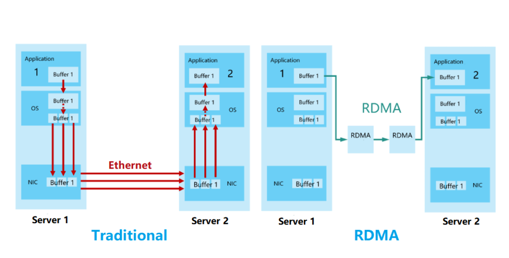
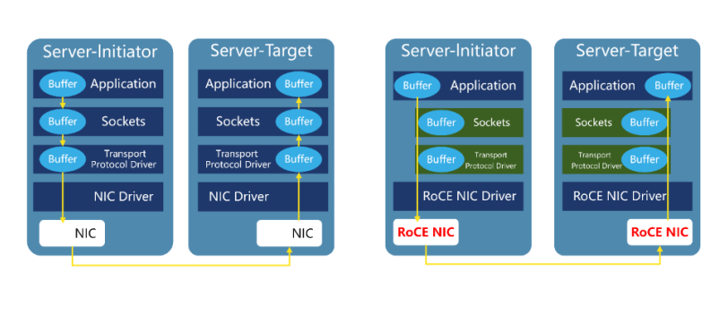
RDMA (Remote Direct Memory Access) protocol
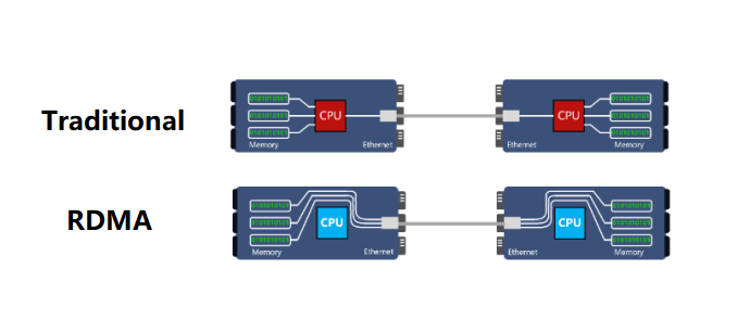
In the traditional TCP/IP, the data from the network card is first copied to the kernel memory, and then copied to the application storage space, or the data is copied from the application space to the kernel memory and then sent to the Internet via the network card. This I/O operation mode requires the conversion of the kernel memory. It increases the length of the data flow transmission path, increases the CPU load, and also increases the transmission latency.
RDMA’s kernel bypass mechanism allows direct data read and write between the application and the network card, reducing the data transmission latency within the server to close to 1us.
At the same time, RDMA’s memory zero-copy mechanism allows the receiver to directly read data from the sender’s memory, bypassing the participation of the kernel memory, greatly reducing the CPU load and improving the CPU efficiency.
The background of InfiniBand
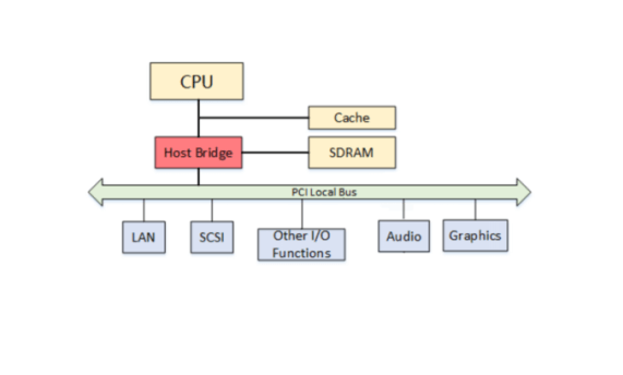
InfiniBand (abbreviated as IB) is a powerful communication technology protocol. Its English translation is “infinite bandwidth”. It was born in the 1990s, to replace the PCI (Peripheral Component Interconnect) bus. The PCI bus was introduced by Intel into the PC architecture, and the upgrade speed was slow, which greatly limited the I/O performance and became the bottleneck of the entire system.
The development history of InfiniBand
In the 1990s, Intel, Microsoft, and SUN led the development of the “Next Generation I/O (NGIO)” technology standard, while IBM, Compaq, and HP led the development of “Future I/O (FIO)”.
In 1999, the FIO Developers Forum and the NGIO Forum merged and established the InfiniBand Trade Association (IBTA).
In 2000, the InfiniBand architecture specification version 1.0 was officially released.
In May 1999, several employees who left Intel and Galileo Technology founded a chip company in Israel and named it Mellanox.
After Mellanox was established, it joined NGIO. Later, Mellanox joined the InfiniBand camp. In 2001, they launched their first InfiniBand product. Starting in
2003, InfiniBand turned to a new application field, which is computer cluster interconnection.
In 2004, another important InfiniBand non-profit organization was born-OFA (Open Fabrics Alliance).
In 2005, InfiniBand found another new scenario-the connection of storage devices.
Since then, InfiniBand has entered a stage of rapid development.

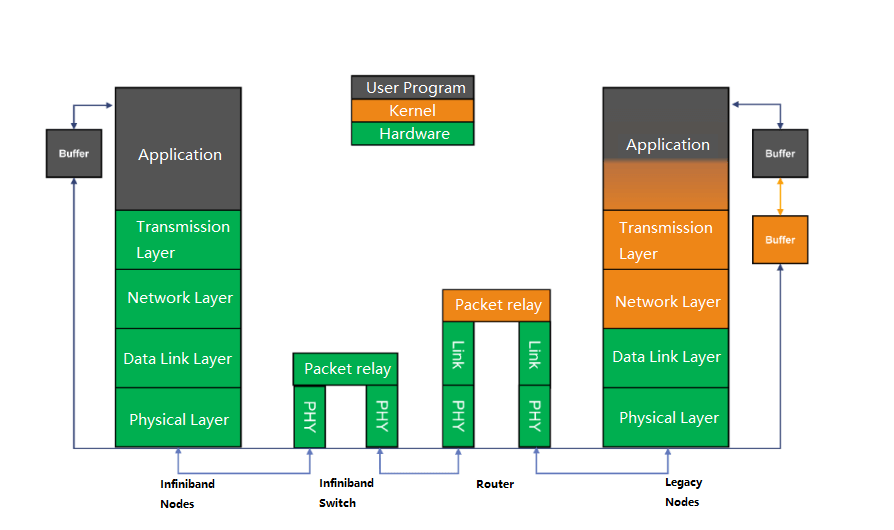
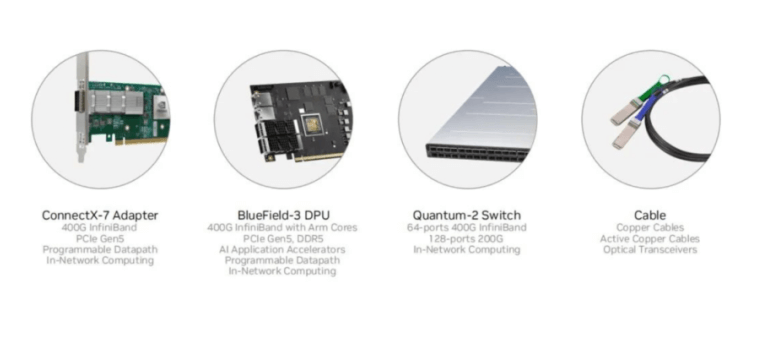
InfiniBand Network Architecture
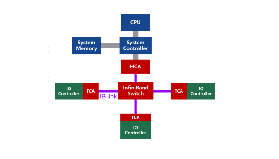
InfiniBand is a channel-based structure, consisting of four main components:
- HCA (Host Channel Adapter), which connects the host to the InfiniBand network.
- TCA (Target Channel Adapter), which connects the target device (such as storage) to the InfiniBand network.
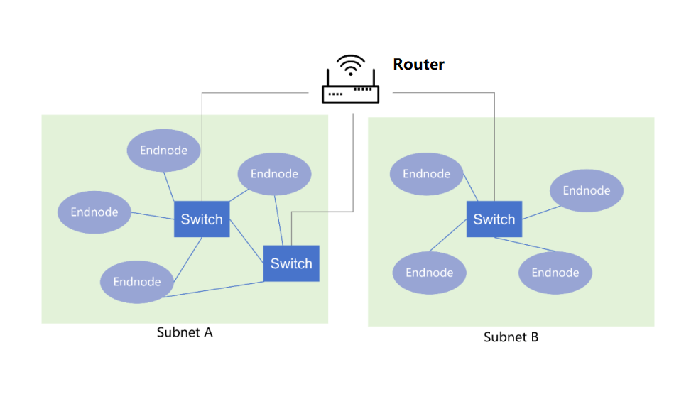
- InfiniBand link, which can be a cable, fiber, or on-board link, connects the channel adapters to the switches or routers.
- InfiniBand switch and router, which provide network connectivity and routing for the InfiniBand network.
- Channel adapters are used to establish InfiniBand channels. All transmissions start or end with channel adapters, to ensure security or work at a given QoS (Quality of Service) level.
Mellanox, acquired by Nvidia in 2020. Since then, it has been widely used in AI large model training.
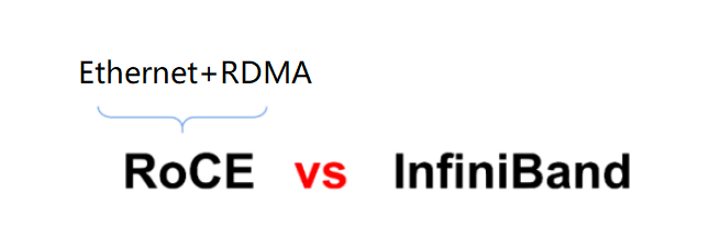
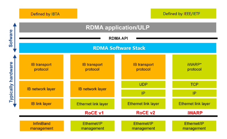
RoCE
The birth of RoCE
In April 2010, IBTA released RoCE (RDMA over Converged Ethernet), which “ported” the RDMA technology in InfiniBand to Ethernet. In 2014, they proposed a more mature RoCEv2. With RoCEv2, Ethernet greatly narrowed the technical performance gap with InfiniBand, and combined with its inherent cost and compatibility advantages, it started to fight back.
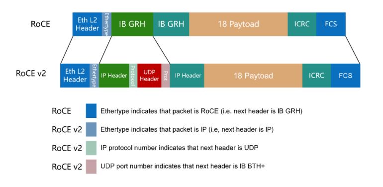
RoCE V2
RoCE v1: An RDMA protocol based on the Ethernet link layer (the switch needs to support flow control technologies such as PFC, to ensure reliable transmission at the physical layer), which allows communication between two hosts in the same VLAN. RoCE V2: Overcomes the limitation of RoCE v1 being bound to a single VLAN. By changing the packet encapsulation, including IP and UDP headers, RoCE 2 can now be used across L2 and L3 networks.
Related Products:
-
 NVIDIA(Mellanox) MMA1B00-E100 Compatible 100G InfiniBand EDR QSFP28 SR4 850nm 100m MTP/MPO MMF DDM Transceiver Module
$40.00
NVIDIA(Mellanox) MMA1B00-E100 Compatible 100G InfiniBand EDR QSFP28 SR4 850nm 100m MTP/MPO MMF DDM Transceiver Module
$40.00
-
NVIDIA(Mellanox) MMA1T00-HS Compatible 200G Infiniband HDR QSFP56 SR4 850nm 100m MPO-12 APC OM3/OM4 FEC PAM4 Optical Transceiver Module
$139.00
-
NVIDIA(Mellanox) MMS1W50-HM Compatible 200G InfiniBand HDR QSFP56 FR4 PAM4 CWDM4 2km LC SMF FEC Optical Transceiver Module
$650.00
-
NVIDIA MMS4X00-NS400 Compatible 400G OSFP DR4 Flat Top PAM4 1310nm MTP/MPO-12 500m SMF FEC Optical Transceiver Module
$700.00
-
NVIDIA MFP7E20-N050 Compatible 50m (164ft) 8 Fibers Low Insertion Loss Female to Female MPO12 to 2xMPO12 Polarity B APC to APC LSZH Multimode OM4 50/125
$145.00
-
NVIDIA MFP7E20-N015 Compatible 15m (49ft) 8 Fibers Low Insertion Loss Female to Female MPO12 to 2xMPO12 Polarity B APC to APC LSZH Multimode OM3 50/125
$67.00
-
NVIDIA MFS1S90-H015E Compatible 15m (49ft) 2x200G QSFP56 to 2x200G QSFP56 PAM4 Breakout Active Optical Cable
$830.00
-
NVIDIA MMA4Z00-NS-FLT Compatible 800Gb/s Twin-port OSFP 2x400G SR8 PAM4 850nm 100m DOM Dual MPO-12 MMF Optical Transceiver Module
$650.00
-
NVIDIA MMS4X00-NM-FLT Compatible 800G Twin-port OSFP 2x400G Flat Top PAM4 1310nm 500m DOM Dual MTP/MPO-12 SMF Optical Transceiver Module
$1199.00
-
NVIDIA MFS1S50-H015V Compatible 15m (49ft) 200G InfiniBand HDR QSFP56 to 2x100G QSFP56 PAM4 Breakout Active Optical Cable
$505.00
-
NVIDIA MMA4Z00-NS Compatible 800Gb/s Twin-port OSFP 2x400G SR8 PAM4 850nm 100m DOM Dual MPO-12 MMF Optical Transceiver Module
$650.00
-
NVIDIA MMS4X00-NM Compatible 800Gb/s Twin-port OSFP 2x400G PAM4 1310nm 500m DOM Dual MTP/MPO-12 SMF Optical Transceiver Module
$900.00
-
NVIDIA NVIDIA(Mellanox) MCX653105A-HDAT-SP ConnectX-6 InfiniBand/VPI Adapter Card, HDR/200GbE, Single-Port QSFP56, PCIe3.0/4.0 x16, Tall Bracket
$1400.00
-
NVIDIA(Mellanox) MCP7H50-H003R26 Compatible 3m (10ft) Infiniband HDR 200G QSFP56 to 2x100G QSFP56 PAM4 Passive Breakout Direct Attach Copper Cable
$75.00
-
NVIDIA(Mellanox) MFS1S50-H003E Compatible 3m (10ft) 200G HDR QSFP56 to 2x100G QSFP56 PAM4 Breakout Active Optical Cable
$480.00
-
NVIDIA NVIDIA(Mellanox) MCX75510AAS-NEAT ConnectX-7 InfiniBand/VPI Adapter Card, NDR/400G, Single-port OSFP, PCIe 5.0x 16, Tall Bracket
$1650.00