The two common package types for 400G optical modules are OSFP and QSFP-DD.
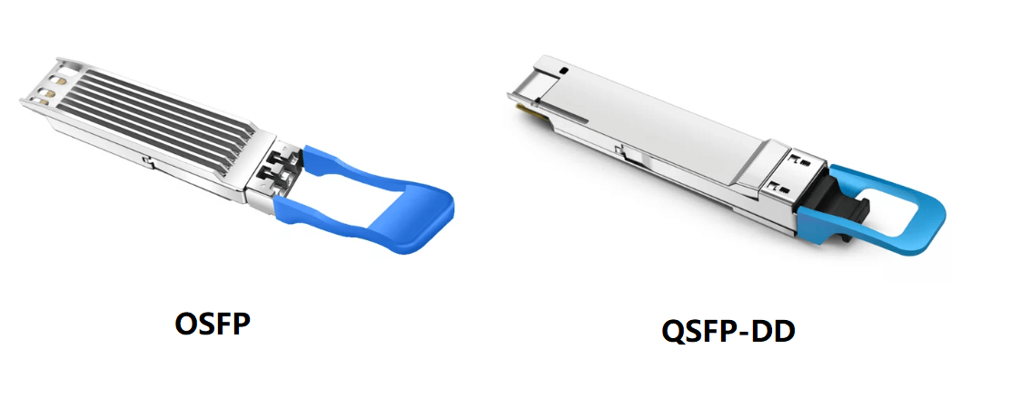
The advantages of 400G QSFP-DD are simplicity and compatibility. The advantage of 400G OSFP is that it has good thermal performance and can be extended to 800G.
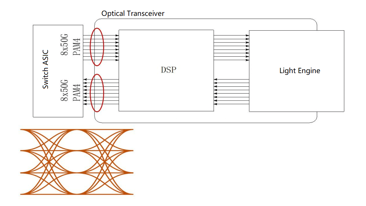
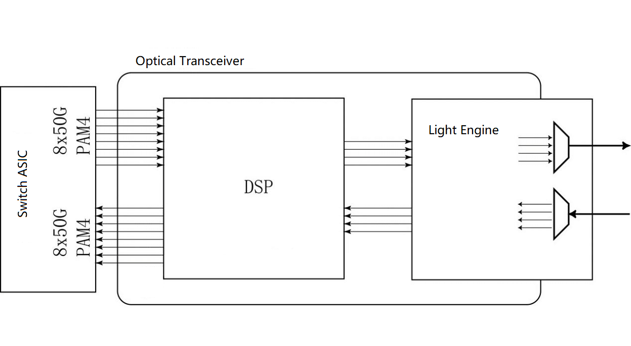
For 400G, the electrical signaling for both OSFP and QSFP-DD interfaced to the host is 8x50G PAM4.
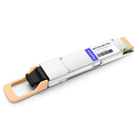
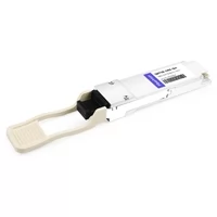
400G QSFP-DD Multi-mode optical modules are divided into 400G QSFP-DD SR8 and 400G QSFP-DD SR4.2.
400G QSFP-DD SR8
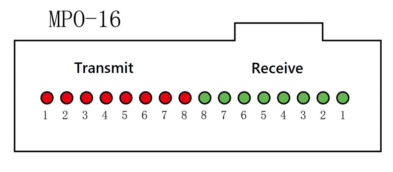
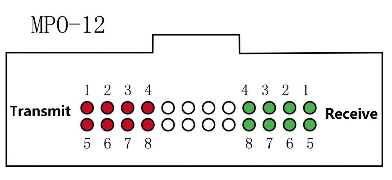
S is the initial letter of short distance, indicating a transmission distance of 100 meters. “8” indicates 8 optical signal channels, each with 50G PAM4. Therefore, 8 transmit and 8 receive require 16 optical fibers, generally using MPO connection. MPO-16 and MPO-12 are commonly used.
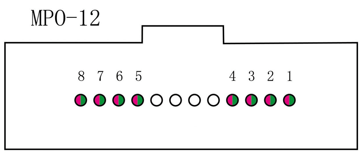
The SR of SR4.2 also means short distance, 100 meters transmission distance, “4” is four fiber channels, and “2” is each channel has 2 wavelengths of two-way multiplexing. Each channel is 2x50G PAM4 and requires 8 optical fibers.
With the MPO-12 connector, this approach’s driving factor is to continue using the MPO-12 cable from the previous generation without replacement.
| Type | Distance | Fiber Type | Connector | Number of fiber | Wavelength | Optical Modulation Signal |
| 400G SR8 | 100m | Multi-mode | MPO-16 APC
MPO-12×2 APC |
16 | 850nm | 50G PAM4 |
| 400G SR4.2 | 100m | Multi-mode | MPO-12 APC | 8 | 850nm
910nm |
50G PAM4 |
400G multi-mode optical modules
400G QSFP-DD single-mode optical module interface
The single-mode 400G interface is divided into two groups, one group is 8x50G PAM4 for the electrical port, and 8x50G PAM4 for the optical port.
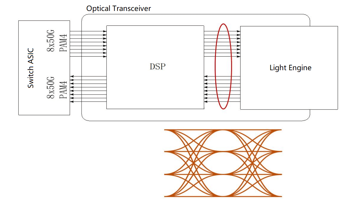
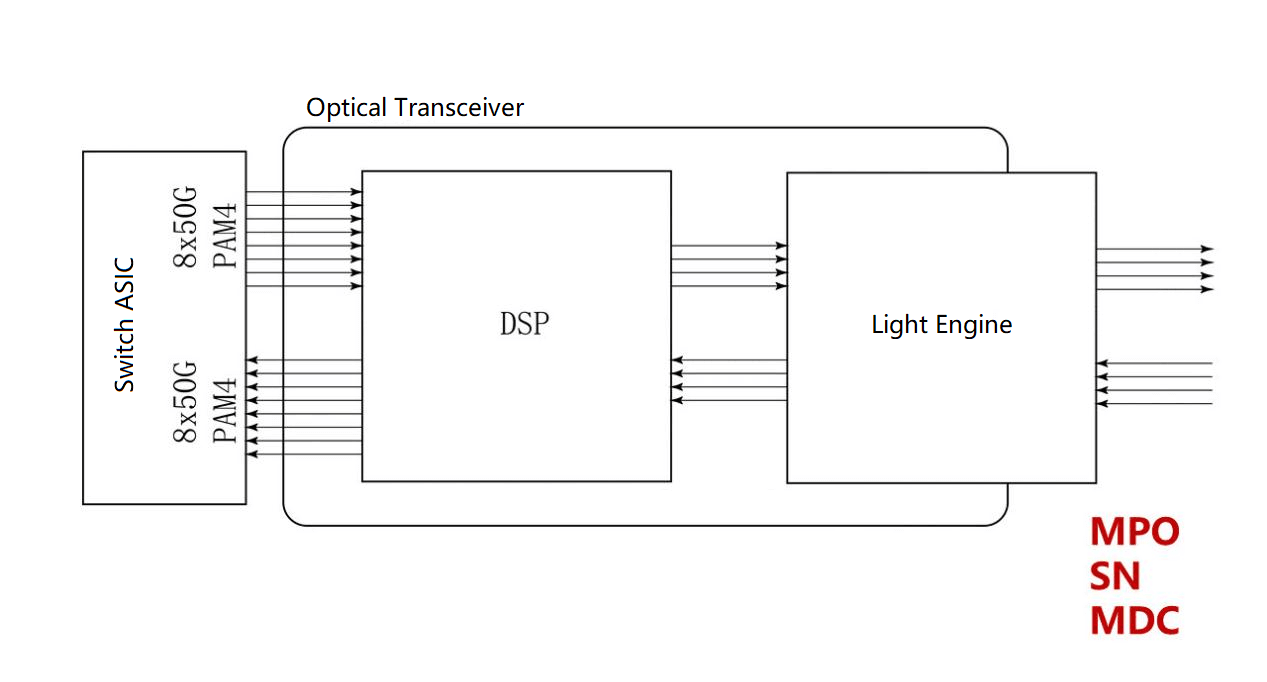
The other group is 8x50G PAM4 for electrical ports and 4x100G PAM4 for optical ports.
It is the same for the electrical interface to the motherboard and the optical module, and both approaches use DSP as well. The difference lies in the output rate of the optical signal, and the number of lasers used.
8x50G PAM4 Single-mode Optical Module
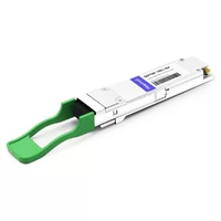
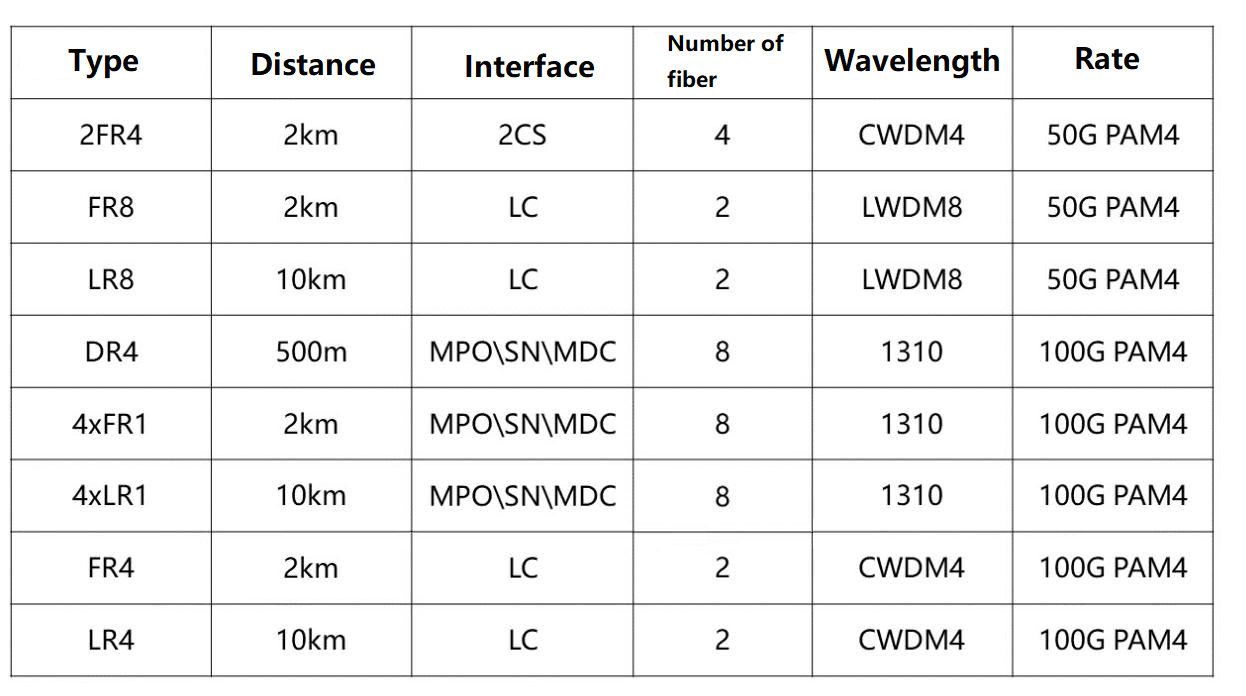
8x50G Optical Module Types FR8, LR8 and 2xFR4
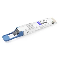
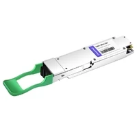
FR8, LR8, “8” is eight wavelengths, 50G PAM4 per wavelength, FR means distance 2km, LR means 10km, 8 wavelengths multiplexed with a single fiber. FR8 and LR8 are dual LC optical interfaces.
F refers to Far, indicating 2km, a little farther than the common 500 meters (DR, datacenter). This is a new distance division in 802.3, inserting two subdivided distances, DR and FR, between SR and LR.
L refers to Long, longer than SR, said 10km. Early 802.3 is SR short distance of 100 meters, LR long distance of 10km so divided, mainly used to mark the length of the metro network distance.
Later, more and more Ethernet optical modules were used in the data center, and they first set the distance of 100G optical modules such as 500m PSM4 and 2km CWDM4.
Until the 802.3 standard of 200G and 400G was formulated, a 500-meter DR And 2km FR were inserted between SR and LR to cover the distance labeling of the data center field.
The 2xFR4, like the LR8 and FR8, uses eight lasers, but only four wavelengths, which are used in two groups for a total of eight channels. A CS interface is used to form the 2x200G form factor.
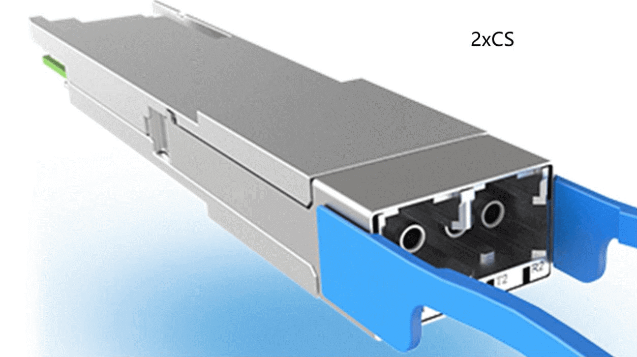
Use two CS connectors, 2xFR4 solution.
The advantages are better link budget and less dispersion with 4 wavelengths than with 8 wavelengths.
The disadvantage is that the optical package is more complex and the production cost is high. In fact, the industry chain of four wavelengths is more mature and the material cost is decreasing.
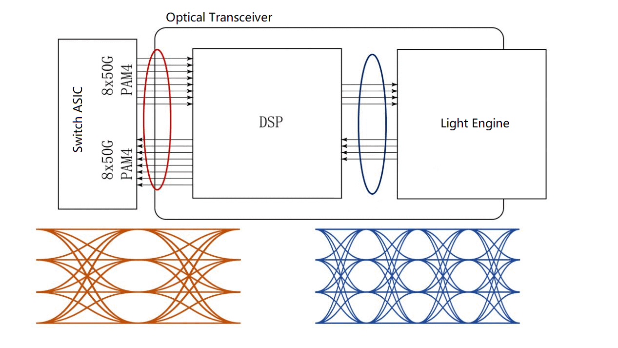
4x100G PAM4 Single-mode Optical Module
Currently, the industry chain focuses on 4x100G solutions, and the most important of these solutions is the DSP with a gearbox.
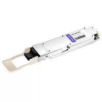
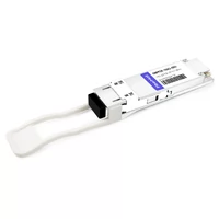
400G DR4, 4xFR1, 4xLR1
The DSP needs to convert 8x50G electrical signals into 4x100G, which is supplied to the EML or silicon optical modulator and output. Each channel is at 1310nm and requires 8 fibers (4 transmitters and 4 receivers).
The ones used are independent fibers that support 400G optical modules in parallel with 1x100G module conversion.
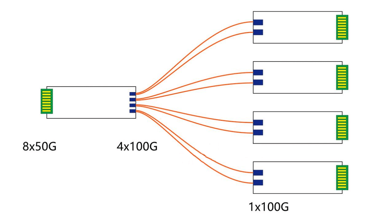
These interfaces are called differently by different manufacturers but are essentially the same.
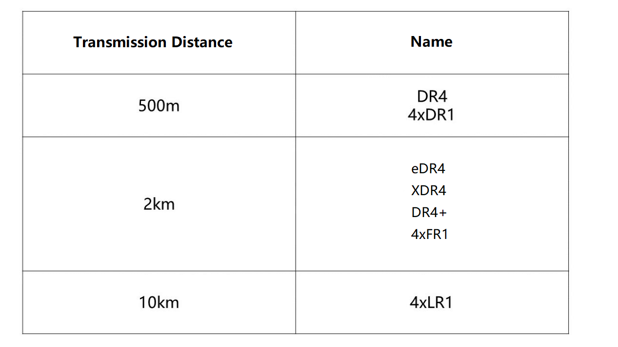
DR4 and 4xDR1 are the same. The wavelengths are all 1310nm, transmit four fibers, and receive four wavelengths.
But FR4 and 4xFR1 are not the same product, FR4 is four wavelengths of one fiber, and 4xFR1 is a wavelength of four fibers.
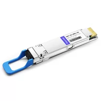
There are three common optical interfaces for 400G DR4, 4xFR1, 4xLR1, one MPO-12, one SN, and one MDC.
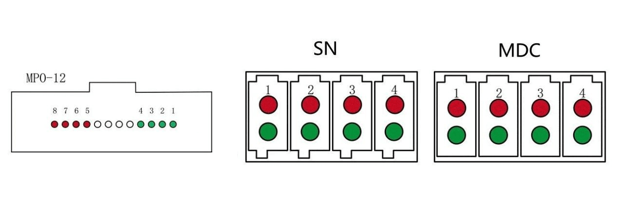
The SN and MDC are from different manufacturers, but the concept is the same.
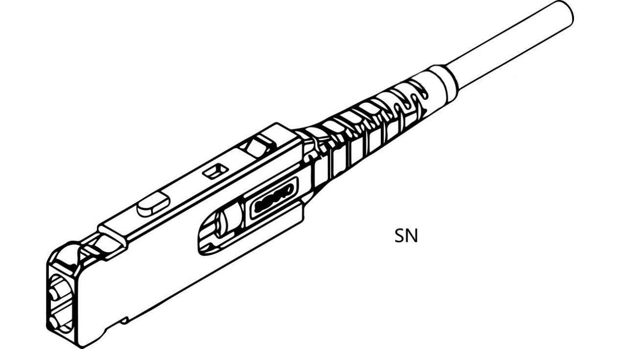
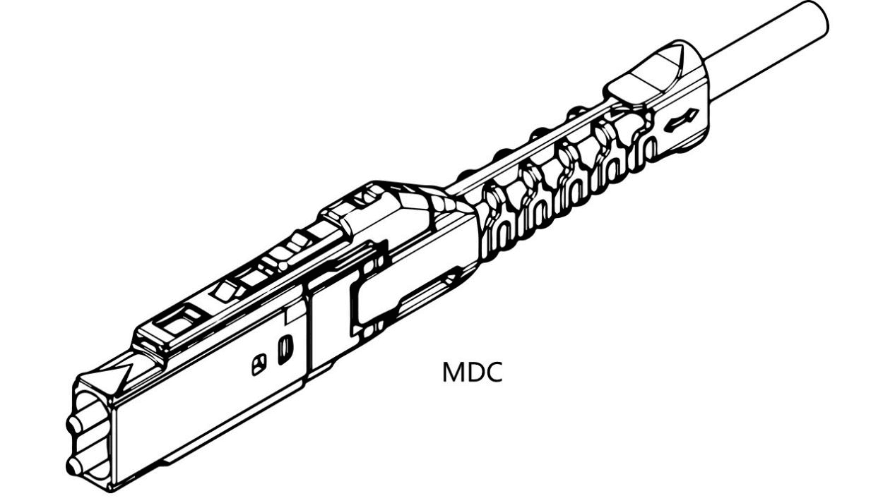
They are both independently Tx and RX pluggable. Compared with MPO, SN, and MDC are more flexible and easier to deploy optical fibers.
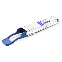
FR4 and LR4
FR4 and LR4 have the same DSP function as DR4 with four wavelengths. Their difference lies in the optical path. the wavelength of CWDM4 uses Mux and Demux to combine and divide the wave. The number of fibers is reduced and LC optical interface is used.
LR4 has two transmission distances, the IEEE standard is 6km, and 100G Lamda MSA is defined as 10km.
400G single-mode interface
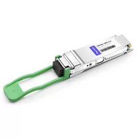
100G PAM4
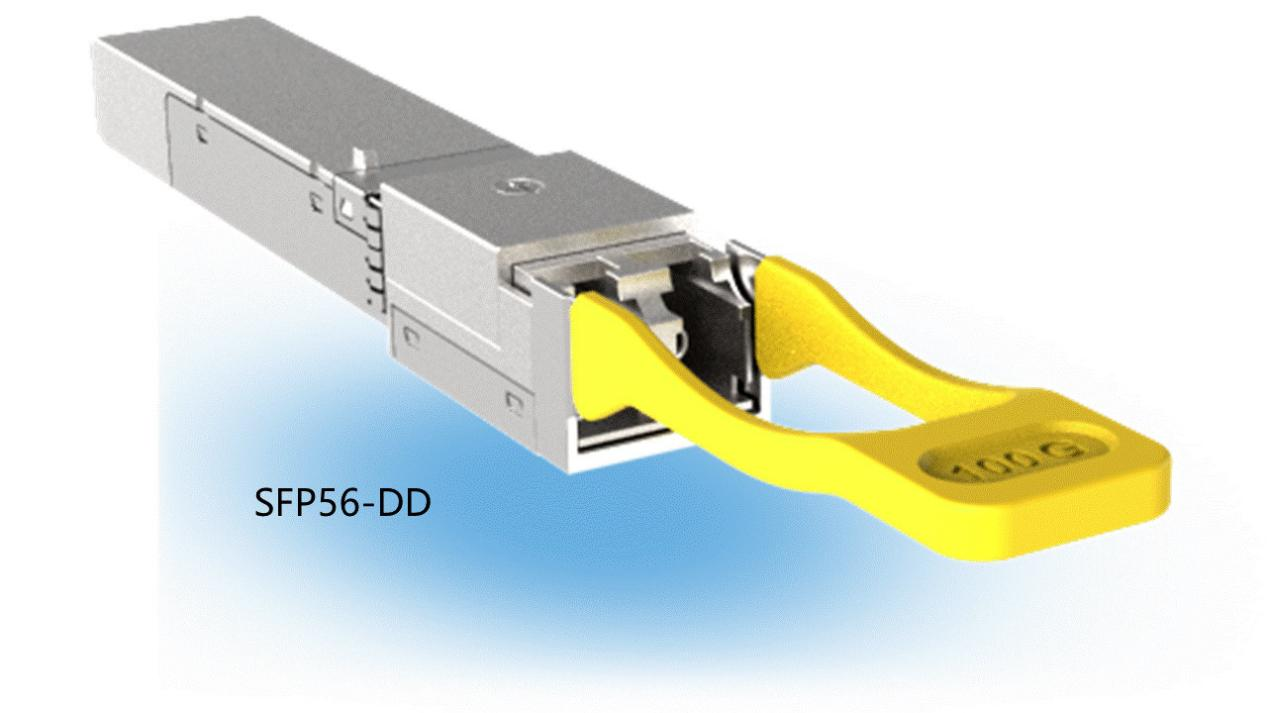
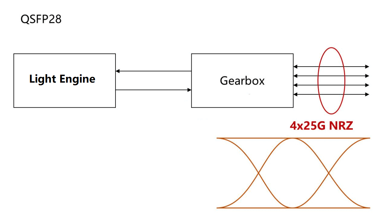
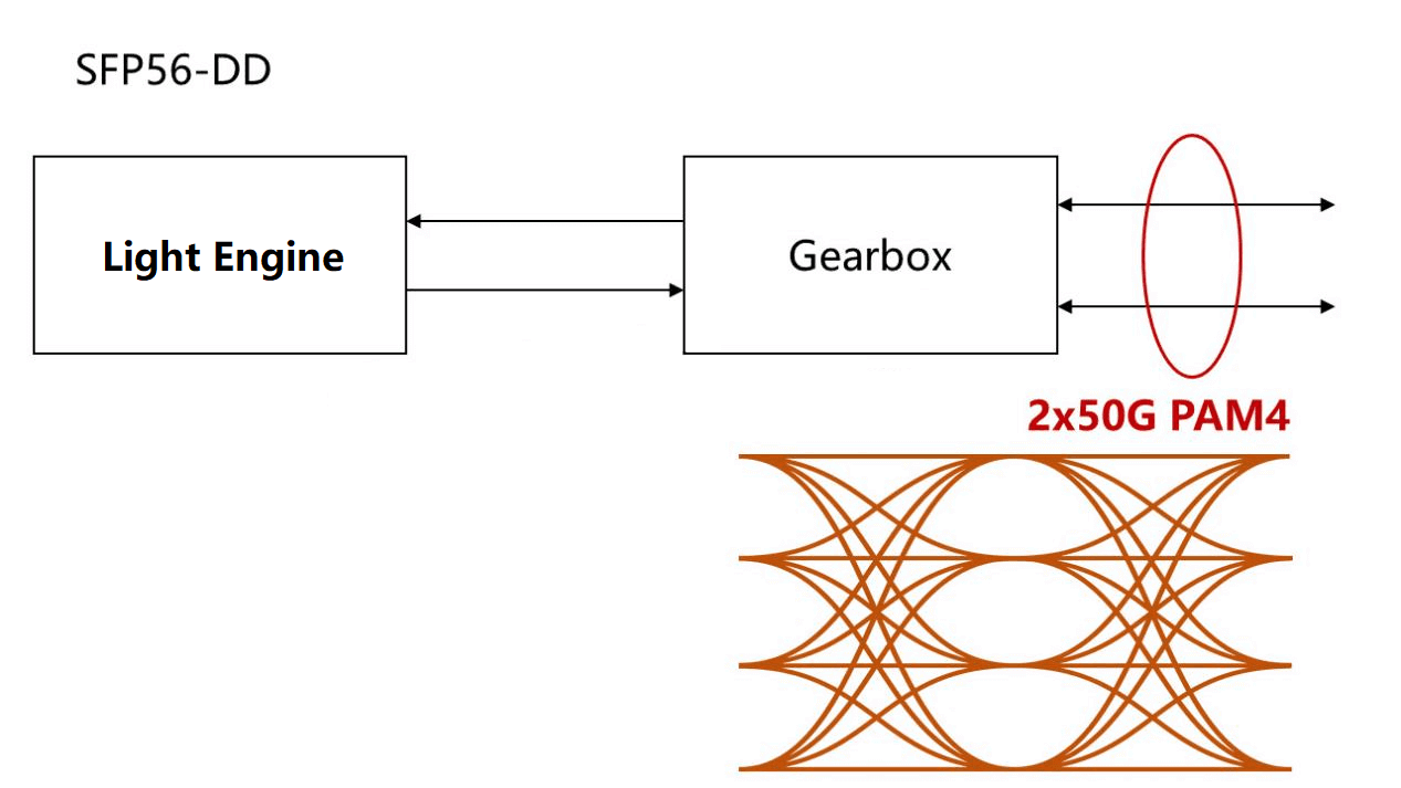
The 100G PAM4 optical module has two splice packages, one is QSFP28 and the other is SFP56-DD.
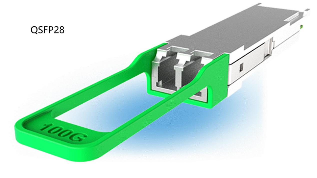
The electrical interface of the QSFP28 package is 25G NRZ.
The electrical interface of the SFP56-DD package is 50G PAM4.
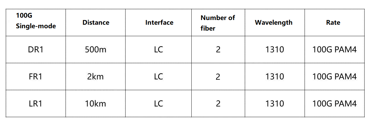
Single-mode 100G
Now 4x100G QSFP-DD is interoperable with 100G single wavelength PAM4, interoperable with QSFP28 need to do electrical interface of the gearbox 1:4, DSP needs to have on/off KR4 FEC option.
With SFP56-DD, the DSP’s gearbox needs to be 1:2 and no KP4 FEC is required (done on the system side).
Summary of single-wave 100G optical modules
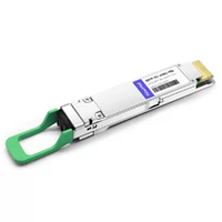
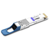
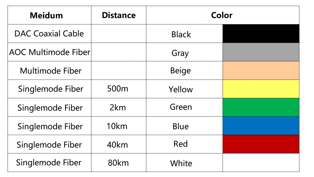
Most manufacturers set the latch color by OSFP MSA protocol.
100G Optical Module Laser Chip and silicon photonics Technology
In the 100G optical module market, the 100G QSFP28 optical module has a large market share, and different QSFP28 optical modules use different lasers.
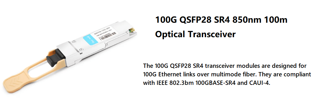
100G-SR4 QSFP28 optical modules are mainly used for multi-mode parallel solutions within 100m. It mostly adopts VCSEL lasers inside, which have the advantages of small size, high coupling rate, low power consumption, easy integration, and low price.
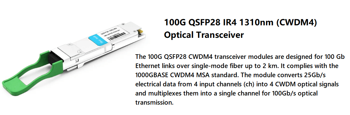
100G-CWDM4 QSFP28 packaged optical modules are mainly used in 10km coarse WDM solutions. Its internal DML laser is mostly used, which has the advantages of small size, low power consumption, and low cost.
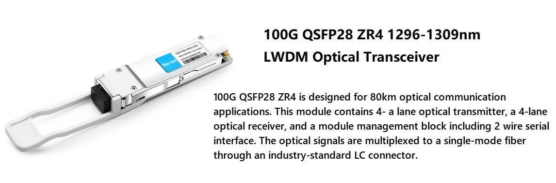
100G ER4 and 100G ZR4 QSFP28 packaged optical modules are mainly used in single-mode solutions for medium and long distances over 40km. Most of its internal EML lasers are used, which have the advantages of large eye diagram margin, small dispersion, large extinction ratio, and long distance.
As for 100G QSFP28 single-wave optical modules, there is a new breakthrough in chip technology — FiberMall’s silicon photonics integrated 100G optical modules for data center scenarios have long been in mass production. And there is a lower BOM (parts and materials) cost advantage, covering the transmission distance were: 500m, 2km, 10km and other single-mode solutions.
At present, the technical route of optical integrated commercial products is mainly divided into III-V group and Si two camps, among which DFB, DML, EML, and other lasers are InP camp. Although the technology is relatively mature, it is costly and incompatible with the CMOS process (integrated circuit process), and its substrate material only doubles every 2.6 years.
While the Si silicon optoelectronic devices use the COMS process to realize the single chip integration of passive optoelectronic devices and integrated circuits and can be integrated on a large scale. With the advantage of high density, its substrate material can be doubled every 1 year.
Currently, 100G optical modules have opened the door to silicon photonics technology, but its development still faces some challenges.
First, the silicon-based integrated laser light source needs to be solved. Silicon is an indirect bandgap semiconductor, compared to direct bandgap semiconductors such as InP, silicon photonics modules need to introduce a separate light source, and if the light source does not comply with Moore’s law, the more coupled integration of the higher cost will continue to offset the cost advantage of silicon materials and process integration.
Secondly, silicon photonics transceiver packaging is difficult and has a low yield. Silicon optical interface packaging is in the early stages, the main bottleneck lies in the optoelectronic chip and fiber array formation of optical interface packaging. Its alignment and packaging precision requirements are high, and packaging efficiency is low. In the current stage of packaging, technology is difficult to achieve high-quality, low-cost packaging. Product yield limits the mass production of silicon photonics modules.
In addition, there are few resources available for the mass production of SiP chips. Although silicon photonics chips are compatible with CMOS processes, mature CMOS resources are not open to the public or there is no silicon photonics flow experience.
At present, the 100G network is still the mainstream, 100G QSFP28 optical module laser chip although VCSEL, EML, and DML are mainly. But in the long term, the silicon photonics solution will be in the era of 400G optical modules or will be a large-scale force.
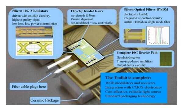
Silicon photonics module, simply put, is the use of silicon photonic technology on a silicon chip integrated photoelectric conversion and transmission module. It is the combination of microelectronics and optoelectronics on a silicon-based platform to form a new silicon optical device.
Related Products:
-
 QSFP-DD-400G-DR4 400G QSFP-DD DR4 PAM4 1310nm 500m MTP/MPO SMF FEC Optical Transceiver Module
$400.00
QSFP-DD-400G-DR4 400G QSFP-DD DR4 PAM4 1310nm 500m MTP/MPO SMF FEC Optical Transceiver Module
$400.00
-
QSFP-DD-400G-LR4 400G QSFP-DD LR4 PAM4 CWDM4 10km LC SMF FEC Optical Transceiver Module
$600.00
-
QSFP-DD-400G-FR4 400G QSFP-DD FR4 PAM4 CWDM4 2km LC SMF FEC Optical Transceiver Module
$500.00
-
QSFP-DD-400G-LR8 400G QSFP-DD LR8 PAM4 LWDM8 10km LC SMF FEC Optical Transceiver Module
$2500.00
-
QSFP-DD-400G-SR8 400G QSFP-DD SR8 PAM4 850nm 100m MTP/MPO OM3 FEC Optical Transceiver Module
$149.00
-
QSFP-DD-400G-SR4.2 400Gb/s QSFP-DD SR4 BiDi PAM4 850nm/910nm 100m/150m OM4/OM5 MMF MPO-12 FEC Optical Transceiver Module
$900.00
-
OSFP-400G-FR4 400G FR4 OSFP PAM4 CWDM4 2km LC SMF FEC Optical Transceiver Module
$900.00
-
OSFP-400G-SR8 400G SR8 OSFP PAM4 850nm MTP/MPO-16 100m OM3 MMF FEC Optical Transceiver Module
$400.00
-
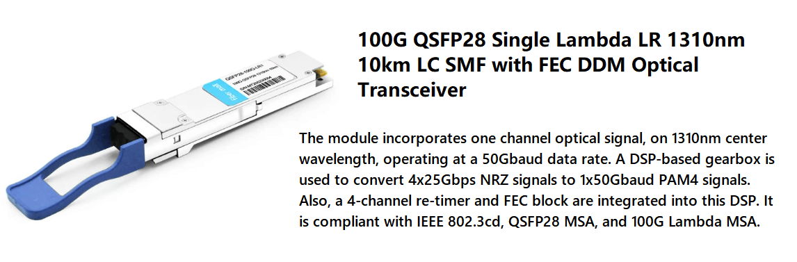
QSFP28-100G-LR1 100G QSFP28 Single Lambda LR 1310nm 10km LC SMF with FEC DDM Optical Transceiver
$265.00
-
QSFP28-100G-SR4 100G QSFP28 SR4 850nm 100m MTP/MPO MMF DDM Transceiver Module
$40.00
-
QSFP28-100G-IR4 100G QSFP28 IR4 1310nm (CWDM4) 2km LC SMF DDM Transceiver Module
$110.00
-
QSFP28-100G-ZR4 100G QSFP28 ZR4 1296-1309nm LWDM 80km LC SMF DDM Transceiver Module
$1500.00
-
QSFP28-100G-FR1 100G QSFP28 Single Lambda FR 1310nm 2km LC SMF with FEC DDM Optical Transceiver
$215.00
-
QSFP28-100G-DR1 100G QSFP28 Single Lambda DR 1310nm 500m LC SMF with FEC DDM Optical Transceiver
$180.00