Foreword
The data center industry has already adopted 800G/1.6T optical modules on a large scale, and the demand for cold plate liquid cooling of optical modules has increased significantly. To meet this industry demand, OSFP-MSA V5.22 version has added solutions applicable to cold plate liquid cooling. At present, there are already some solutions for single-layer optical modules in the industry, such as heat pipe + remote cold plate schemes, etc. However, for Stack cage optical modules with cold plate liquid cooling, no mature technical solution has been provided by the industry yet, and many suppliers are still prototyping and researching new technical solutions. This article summarizes and organizes the design constraints related to Stack-OSFP optical module cold plate liquid cooling as specified in the latest MSA protocol.
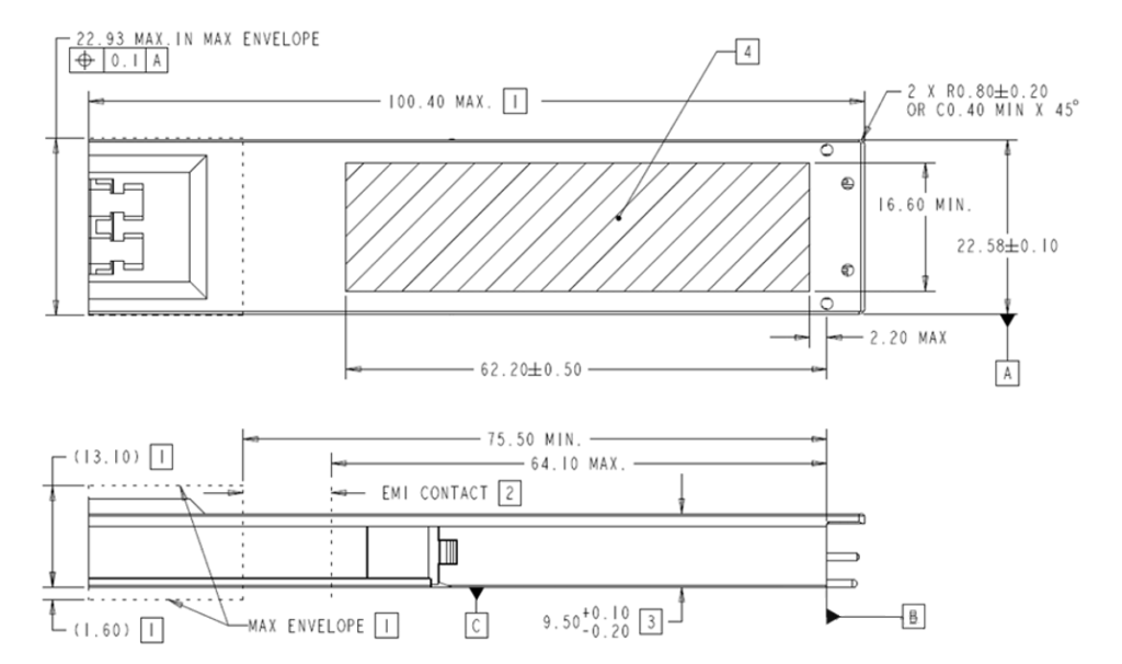
OSFP Module Body Dimensions (Without IHS)
To accommodate cold plate liquid cooling for optical modules, the OSFP optical module needs to remove the IHS. At this time, the dimensions of the optical module body are as follows:
- Module width 22.58 mm
- Module height 9.5 mm, with tolerance of -0.2 ~ 0.1 mm, i.e., the maximum dimensional deviation of the optical module body is 0.3 mm
- Allowed contact area with cold plate: 16.6 mm × 62.2 ± 0.5 mm
Stack Cage for Cold Plate Liquid Cooling
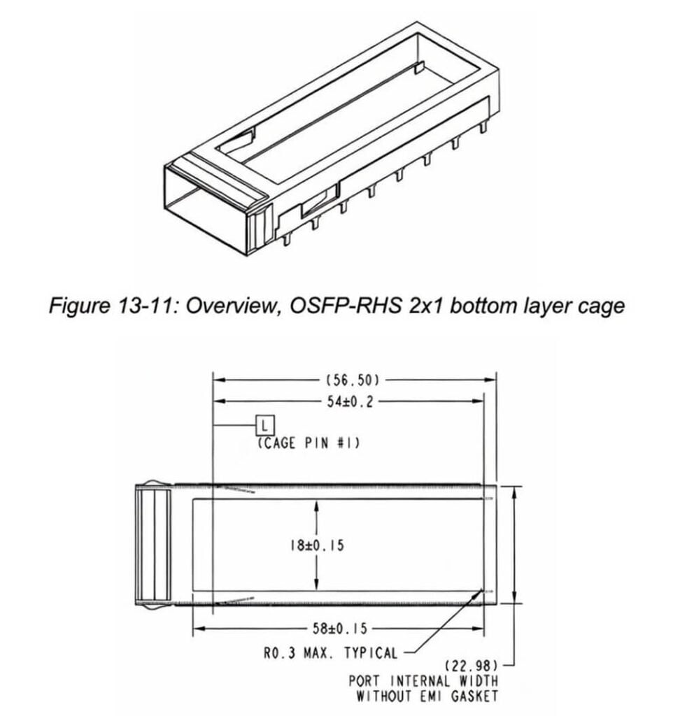
To meet the cold plate liquid cooling requirement for dual-layer optical modules, the Stack cage dimensions have undergone significant changes. The cage is changed to a two-segment split type, which can support segmented installation:
Height from the upper cover of the lower cage to the PCB board: 11.15 mm
Dual-layer cage clearance height space: 9.5 mm, maximum depth 68 mm, can accommodate lower-layer optical module cold plate
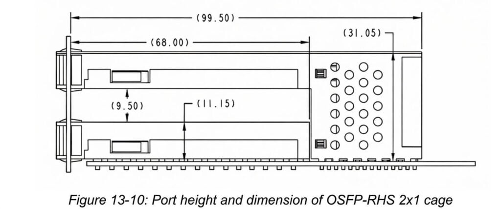
Total cage height: 31.05 mm Upper cage opening area: 61.6 × 18 mm, cold plate boss area must be smaller than this size to allow installation and fit the optical module.
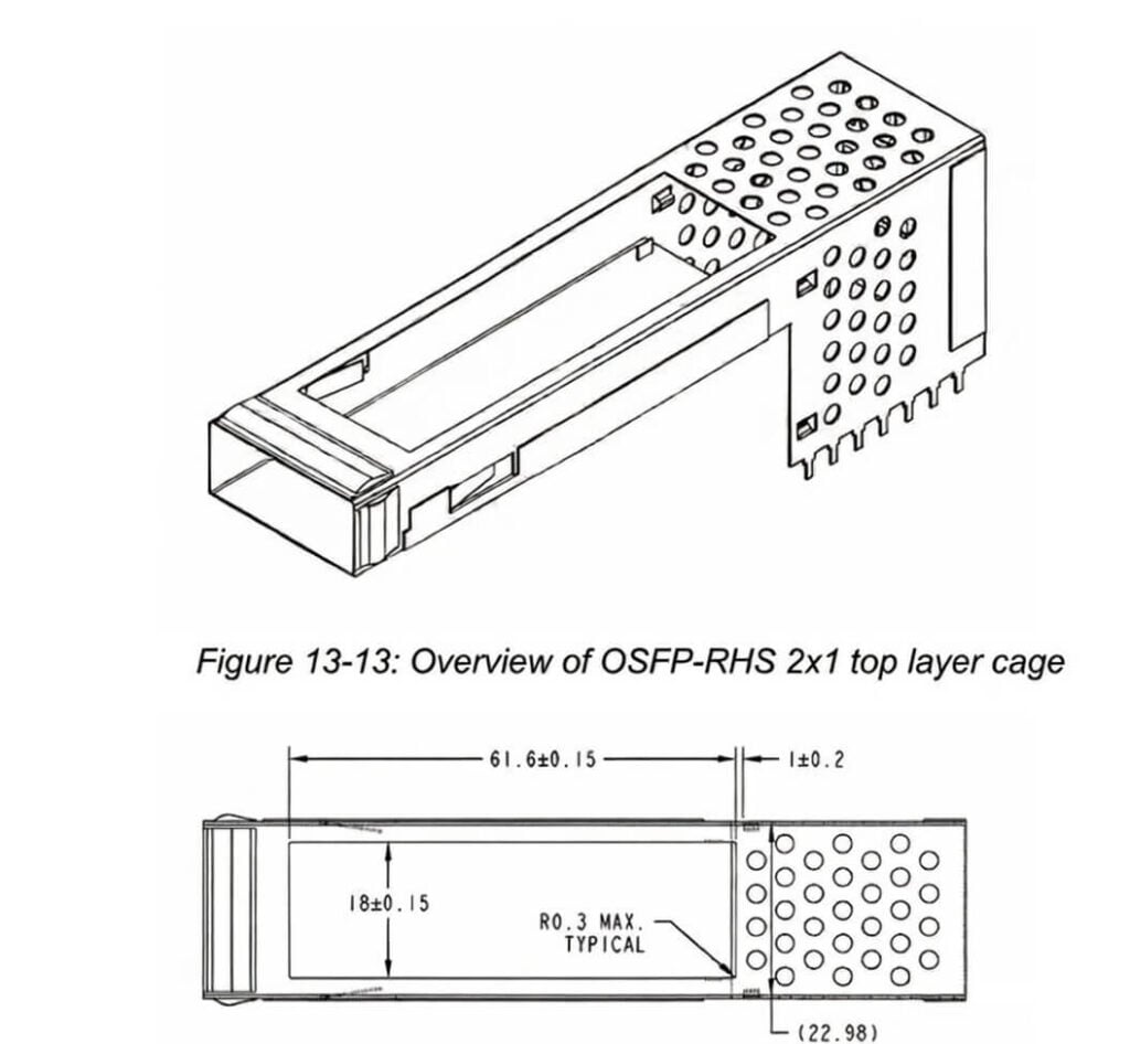
To enhance cage strength, a certain width is reserved at the rear end, and the maximum opening size is adjusted to 58 × 18 mm.
The length direction is reduced by 3.6 mm compared to the upper cage. If it is desired to keep the upper and lower layer optical module cold plate structures consistent, the design should follow the lower-layer opening dimensions at this time.
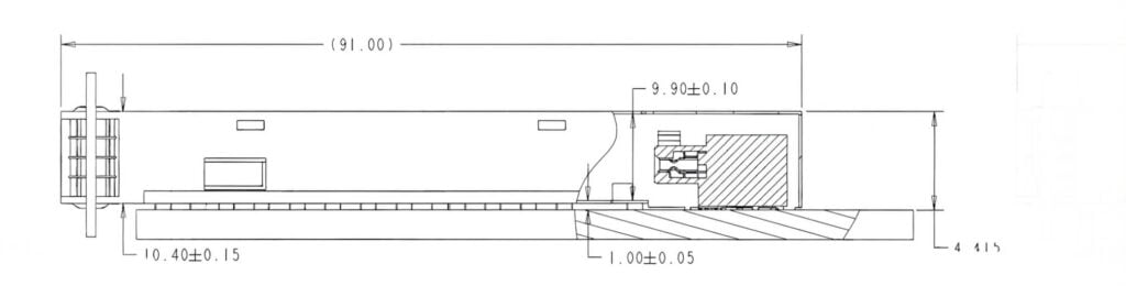
The net height dimension given for single-layer cage is 9.9 ± 0.1 mm. It can be seen that the maximum possible gap range between the cage and the optical module is 0.2 ~ 0.7 mm.
Additional OSFP Module Thermal & Mechanical Requirements
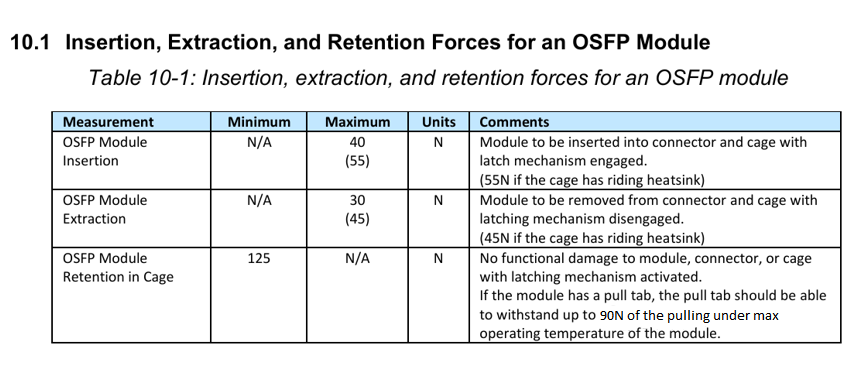
Insertion/Extraction Force
- Maximum insertion force 40 N (with RHS maximum 55 N);
- Maximum extraction force 30 N (with RHS maximum 45 N). When the optical module adopts cold plate liquid cooling, it should be considered the same as the RHS scenario, so the maximum insertion force should be taken as 55 N.
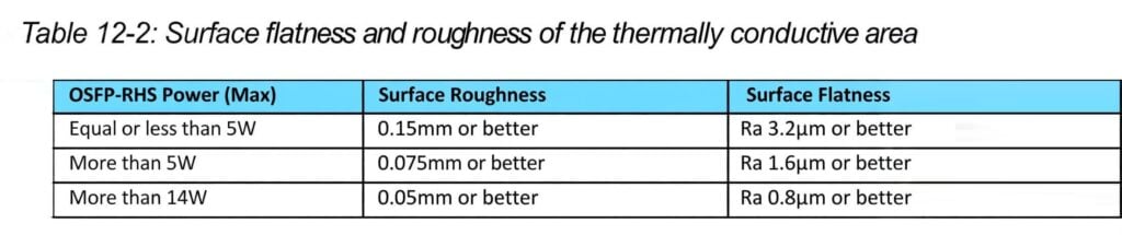
Optical Module Flatness Requirement
For scenarios above 14 W, corresponding to 800G and higher optical modules, the surface flatness of the optical module is required to be no higher than 0.05 mm, roughness Ra 0.8 μm. When designing the optical module cold plate, it should be designed according to this requirement.
Optical Module RHS Downforce Requirement
The MSA protocol provides two clamping force requirements for OSFP optical modules, both for RHS: Section 5.5 requires not exceeding 36 N, Section 12.8 requires not exceeding 50 N. Since Chapter 12 of the MSA is a chapter specifically updated for OSFP optical modules after removing the IHS, and the cage structure in this chapter is designed with a clearance height of 9.5 mm, for Stack cages, it is recommended to design with a maximum downforce not exceeding 50 N when designing the optical module cold plate. Assuming the lower-layer cold plate contact area with the optical module is 16.6 × 50 mm, the surface pressure under 50 N downforce is approximately 8.3 psi. It can be seen that the contact pressure when the optical module contacts the cold plate is extremely low.
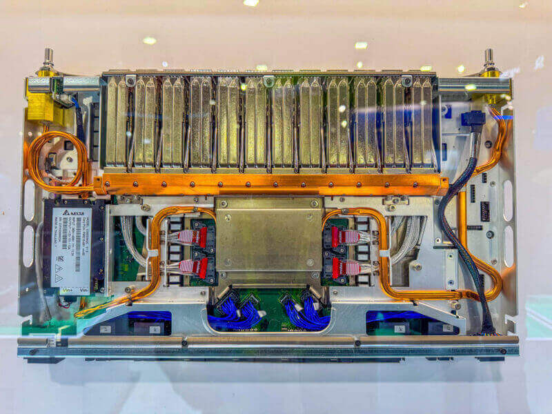
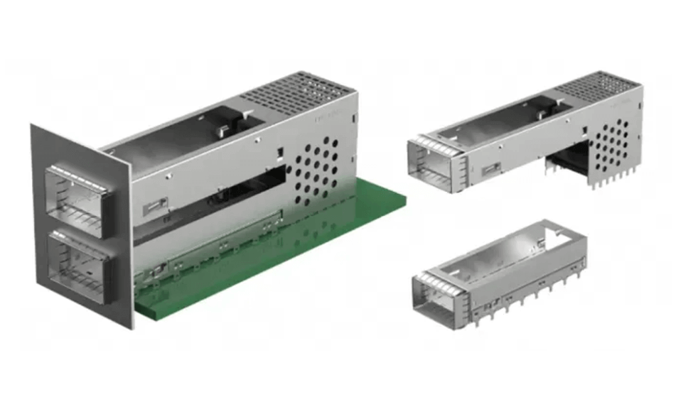
OSFP Optical Module Cage + Cold Plate Physical Samples
The cage structure prototyped according to this version of the MSA protocol is shown below. The lower-layer optical module cold plate needs to provide a highly reliable and relatively low-cost optical module cold plate liquid cooling solution within the dimensional constraints of height 9.5 mm and depth 68 mm.
Currently, some connector manufacturers in the industry have already provided cold plate solutions for Stack cages. For example, the solution provided by Amphenol is an integrated cold plate that supports cold plate liquid cooling for 8 optical modules each on upper and lower layers simultaneously. According to official information, this cold plate has the following characteristics:
- One-piece cold plate shared by 8 optical modules each on upper and lower layers (total 16 ports);
- Maximum cooling capacity 40 W;
- Independent spring loading for each port to ensure contact;
- Only one inlet and one outlet for 16 optical modules, maximizing reliability and reducing leakage risk;
- Fluid water pressure does not affect insertion/extraction force (indicating that the floating part does not contact the coolant, and there are no sliding seal or similar leakage scenarios).
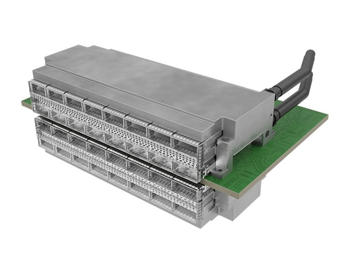
The actual heat dissipation performance of this solution after application still needs to be verified.
Summary
OSFP optical module is the mainstream form factor solution for 800G and 1.6T capacity. The heat dissipation performance and reliability of its cold plate liquid cooling solution are crucial to whether cold plate liquid cooling technology can be widely promoted and applied to optical module liquid cooling. The MSA has already provided the recommended structural design applicable to optical module cold plate liquid cooling. Subsequent cold plate solution designs should refer to the above key constraint information when designing OSFP optical module cold plates.
Related Products:
-
 NVIDIA MMA4Z00-NS Compatible 800Gb/s Twin-port OSFP 2x400G SR8 PAM4 850nm 100m DOM Dual MPO-12 MMF Optical Transceiver Module
$650.00
NVIDIA MMA4Z00-NS Compatible 800Gb/s Twin-port OSFP 2x400G SR8 PAM4 850nm 100m DOM Dual MPO-12 MMF Optical Transceiver Module
$650.00
-
NVIDIA MMA4Z00-NS-FLT Compatible 800Gb/s Twin-port OSFP 2x400G SR8 PAM4 850nm 100m DOM Dual MPO-12 MMF Optical Transceiver Module
$650.00
-
NVIDIA MMS4X00-NM Compatible 800Gb/s Twin-port OSFP 2x400G PAM4 1310nm 500m DOM Dual MTP/MPO-12 SMF Optical Transceiver Module
$900.00
-
NVIDIA MMS4X00-NM-FLT Compatible 800G Twin-port OSFP 2x400G Flat Top PAM4 1310nm 500m DOM Dual MTP/MPO-12 SMF Optical Transceiver Module
$1199.00
-
NVIDIA MMS4X50-NM Compatible OSFP 2x400G FR4 PAM4 1310nm 2km DOM Dual Duplex LC SMF Optical Transceiver Module
$1200.00
-
NVIDIA MMA4Z00-NS400 Compatible 400G OSFP SR4 Flat Top PAM4 850nm 30m on OM3/50m on OM4 MTP/MPO-12 Multimode FEC Optical Transceiver Module
$550.00
-
NVIDIA MMS4X00-NS400 Compatible 400G OSFP DR4 Flat Top PAM4 1310nm MTP/MPO-12 500m SMF FEC Optical Transceiver Module
$700.00
-
OSFP-400G-DR4-FLT 400G OSFP DR4 Flat Top PAM4 1310nm MTP/MPO-12 500m SMF FEC Optical Transceiver Module
$700.00
-
OSFP-400G-SR4-FLT 400G OSFP SR4 Flat Top PAM4 850nm 30m on OM3/50m on OM4 MTP/MPO-12 Multimode FEC Optical Transceiver Module
$550.00
-
OSFP-400G-LR4 400G LR4 OSFP PAM4 CWDM4 LC 10km SMF Optical Transceiver Module
$1199.00
-
OSFP-400G-DR4+ 400G OSFP DR4+ 1310nm MPO-12 2km SMF Optical Transceiver Module
$850.00
-
OSFP-2x200G-FR4 2x 200G OSFP FR4 PAM4 2x CWDM4 CS 2km SMF FEC Optical Transceiver Module
$1500.00