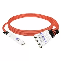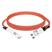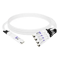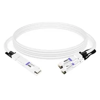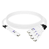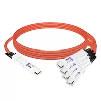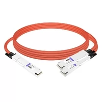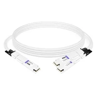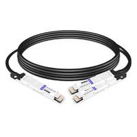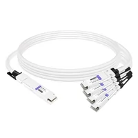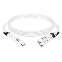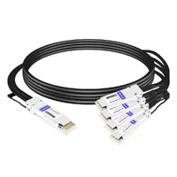

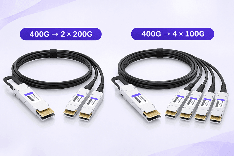
A breakout DAC cable connects one multi-lane switch or NIC port to two, four, or eight lower-speed ports. It doesn’t add bandwidth. Instead, it distributes the electrical lanes available at the parent port among separate child connectors. For example, a 100G QSFP28 port can break out into 4×25G, while a 400G QSFP-DD port can break out into 4×100G or 2×200G when the host platform and child interfaces support these configurations.
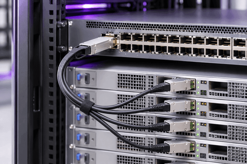
Breakout DACs are widely used in top-of-rack, leaf-spine, storage, and AI network fabrics because they allow one switch port to connect to multiple servers. A 4:1 breakout reduces the number of switch-side physical ports required to connect four endpoints from four to one, a 75% reduction. However, the aggregate bandwidth remains limited by the parent port, and each server receives only the bandwidth of its assigned child link. This is an important trade-off in network design.
What Is a Breakout DAC Cable?
A breakout DAC cable is a factory-terminated twinaxial copper assembly that connects one multi-lane port to two, four, or eight lower-speed ports. It routes the parent port’s electrical lanes to separate child connectors, increasing port density without increasing the total available bandwidth.
The parent end typically uses a QSFP+, QSFP28, QSFP56, QSFP-DD, or OSFP connector. The child ends may use SFP+, SFP28, SFP56, QSFP28, QSFP56, QSFP112, or OSFP connectors, depending on the configuration.
Breakout describes a connection topology, not a specific cable technology. The same breakout configuration can be implemented using passive DAC, ACC, or AEC assemblies. A parent port may support several breakout ratios, but the available configurations are determined by the switch ASIC, host SerDes, port architecture, firmware, and network operating system—not by the cable alone.
Breakout is also not a signal splitter. A splitter duplicates or divides a signal, whereas a breakout cable assigns independent electrical lanes to separate child ports. Each child link uses its own assigned lane group and operates as a separate connection. Link training, autonegotiation, and FEC behavior depend on the PHY and host platform.
Keep three other products separate: a straight-through DAC (1:1), a breakout AOC (optical, typically used for longer reach), and an MPO/MTP optical fanout harness (fiber, not copper). This guide covers copper breakout DACs only. For the underlying cable family, see what a DAC cable is and DAC cable types.
How Breakout DAC Cables Work: Lanes, Lane Groups, and CR Notation
Every high-speed port is built from electrical lanes. A QSFP28 100G interface typically uses four lanes at 25G NRZ. A 400G QSFP-DD interface typically uses eight lanes at 50G PAM4. An 800G OSFP or QSFP-DD800 interface uses eight lanes at 100G PAM4. A 1.6T OSFP1600 interface uses eight lanes at 200G PAM4.
Aggregate speed is calculated by multiplying the number of lanes by the data rate per lane.
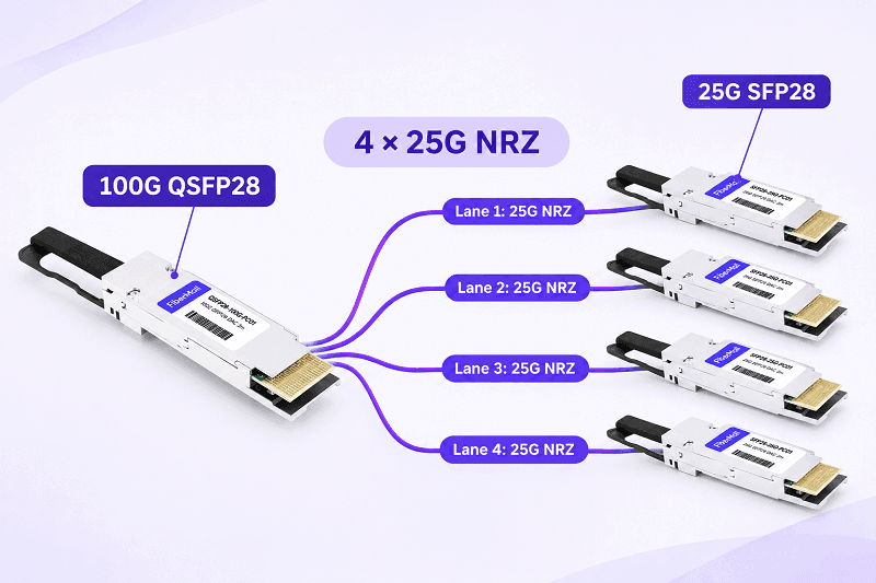
Breakout assigns a group of lanes to each child port. A 100G QSFP28 to 4×25G cable assigns one 25G lane to each SFP28 leg. A 400G QSFP-DD to 2×200G cable assigns four 50G PAM4 lanes to each QSFP56 leg. An 800G OSFP to 2×400G cable assigns four 100G PAM4 lanes to each QSFP112 leg.
CR notation describes the lane count of a copper PHY. CR1 uses one lane, CR2 uses two, CR4 uses four, and CR8 uses eight. The number indicates the lane count, not the aggregate speed. For example, a 400G copper interface can use CR4 with 100G lanes or CR8 with 50G lanes, depending on the PHY implementation.
| Parent port | Lanes | Per-lane rate | Aggregate | Breakout example | Lanes per leg |
| QSFP+ | 4 | 10G NRZ | 40G | 4×10G SFP+ | 1 |
| QSFP28 | 4 | 25G NRZ | 100G | 4×25G SFP28 | 1 |
| QSFP56 | 4 | 50G PAM4 | 200G | 2×100G QSFP56 | 2 |
| QSFP-DD | 8 | 50G PAM4 | 400G | 4×100G QSFP56 | 2 |
| QSFP-DD800 / OSFP800 | 8 | 100G PAM4 | 800G | 2×400G QSFP112 | 4 |
| OSFP1600 / OSFP224-class | 8 | 200G PAM4 | 1.6T | 4×400G OSFP-class | 2 |
Lane mapping is determined by the cable’s internal wiring and the supported host port configuration. Some platforms also use cable EEPROM application descriptors as part of their compatibility checks. It is not something that can normally be rewired in the field. That’s why two cables with identical connectors can behave differently: their internal lane assignments may differ, and the switch may expect a specific mapping.
Label the legs before installation. If a cable establishes a link on leg 1 but not on legs 2 through 4, check the breakout mode, lane mapping, port configuration, FEC settings, and cable integrity before concluding that the cable is defective. The IEEE 802.3 working group defines the Ethernet PHY specifications and lane rates, while relevant SFF and MSA specifications define connector, electrical, and management-interface requirements.
Common Breakout DAC Configurations (40G to 1.6T)
The following table covers common and emerging breakout configurations encountered in 2026. Reach figures are typical product examples, not universal industry limits. Actual reach depends on cable construction, AWG, electrical performance, and host-platform qualification.
| Parent port | Parent lanes | Common breakout | Child signaling | Rate-matched? | Typical reach |
| 40G QSFP+ | 4×10G NRZ | 4×10G SFP+ | 1×10G NRZ | Yes | 0.5–5 m (up to 7 m for some 26 AWG products) |
| 100G QSFP28 | 4×25G NRZ | 4×25G SFP28 | 1×25G NRZ | Yes | 0.5–3 m (up to 5 m for some 26 AWG products) |
| 100G QSFP28 | 4×25G NRZ | 2×50G QSFP28 | 2×25G NRZ | Yes, platform-dependent | 0.5–3 m |
| 200G QSFP56 | 4×50G PAM4 | 2×100G QSFP56 | 2×50G PAM4 | Yes, platform-dependent | 0.5–3 m |
| 200G QSFP56 | 4×50G PAM4 | 4×50G SFP56 | 1×50G PAM4 | Yes | 0.5–2 m |
| 200G QSFP-DD | 8×25G NRZ | 2×100G QSFP28 | 4×25G NRZ | Yes | 0.5–3 m |
| 400G QSFP-DD | 8×50G PAM4 | 2×200G QSFP56 | 4×50G PAM4 | Yes | 0.5–3 m |
| 400G QSFP-DD | 8×50G PAM4 | 4×100G QSFP56 | 2×50G PAM4 | Yes | 0.5–2 m |
| 400G QSFP-DD | 8×50G PAM4 | 8×50G SFP56 | 1×50G PAM4 | Yes | 0.5–1 m |
| 400G QSFP-DD | 8×50G PAM4 | 4×100G QSFP28 | 4×25G NRZ | No; requires an appropriate gearbox | Active, product-dependent (typically 1–3 m) |
| 800G OSFP / QSFP-DD800 | 8×100G PAM4 | 2×400G OSFP / QSFP112 | 4×100G PAM4 | Yes | 0.5–2 m |
| 800G OSFP / QSFP-DD800 | 8×100G PAM4 | 4×200G QSFP112 | 2×100G PAM4 | Yes, platform-dependent | 0.5–2 m |
| 800G OSFP / QSFP-DD800 | 8×100G PAM4 | 8×100G QSFP112 | 1×100G PAM4 | Yes, platform-dependent | 0.5–1 m |
| 1.6T OSFP1600 | 8×200G PAM4 | 2×800G OSFP1600 | 4×200G PAM4 | Yes, platform-dependent | 0.5–1 m |
| 1.6T OSFP1600 | 8×200G PAM4 | 4×400G OSFP1600-class | 2×200G PAM4 | Yes, platform-dependent | 0.5–1 m |
The 1.6T configurations above describe possible lane-group mappings, not guaranteed compatibility across all OSFP platforms. The host port, child interface, and cable assembly must explicitly support the required electrical lane configuration.
40G and 100G: The 4×10G and 4×25G Workhorses
40G QSFP+ to 4×10G SFP+ is one of the oldest and most common breakout configurations. It is generally passive, rate-matched, and available in lengths of 0.5–5 m, with some 26 AWG products reaching 7 m.
100G QSFP28 to 4×25G SFP28 is one of the most common breakout configurations in 25G server access networks. It is rate-matched, generally passive, and commonly available in lengths of 0.5–3 m. A 100G port can also break out into 2×50G on platforms that explicitly support this lane configuration.
200G and 400G: More Ratios, More Rate Traps
A 200G QSFP56 port can break out into 2×100G QSFP56 or 4×50G SFP56, provided the host supports the corresponding lane mapping. Both configurations can be rate-matched.
A 400G QSFP-DD port can break out into 2×200G QSFP56, 4×100G QSFP56, or 8×50G SFP56. These configurations are rate-matched when the child ports use the corresponding 50G PAM4 lanes.
The 400G-to-4×100G QSFP28 configuration is different. A standard 100G QSFP28 interface typically uses four 25G NRZ lanes, while the 400G QSFP-DD parent uses eight 50G PAM4 lanes. These interfaces are not directly rate-matched. A passive lane-mapping cable cannot convert between them. This configuration requires an active breakout assembly with an appropriate gearbox, or another explicitly supported conversion architecture.
800G and 1.6T: Lane Groups Get Wider
An 800G OSFP or QSFP-DD800 port can break out into 2×400G, 4×200G, or 8×100G. The first two configurations can be rate-matched using groups of four or two 100G PAM4 lanes, respectively. The 8×100G configuration assigns one 100G PAM4 lane to each child port and is platform-dependent.
A 1.6T OSFP1600 port uses eight 200G PAM4 electrical lanes. It can potentially break out into 2×800G or 4×400G when the host and child interfaces support the corresponding lane groups. These configurations require careful platform and cable qualification. Passive reach is typically short, with 1.6T products generally intended for very short in-rack connections.
400G to 4×100G is available in two electrically different configurations. One uses QSFP56 child ports operating with two 50G PAM4 lanes per port and can work passively when supported by the host. The other uses standard QSFP28 child ports operating with four 25G NRZ lanes per port and requires an appropriate active gearbox solution. Always check the modulation format and lane count, not just the connector type or aggregate port speed.
Compare 40G to 1.6T breakout assemblies: Explore FiberMall’s DAC, ACC, and AEC breakout cables.
Rate-Matched vs Gearbox Breakout: The Rule That Decides If a Passive DAC Works
Rate-matched breakout maintains the same lane rate and modulation format on both sides. The switch ASIC routes the parent port’s electrical lanes into separate groups for the child ports. No additional retimer, gearbox, or lane-rate conversion is required. This is generally the lowest-power, lowest-latency, and lowest-cost breakout option because it requires no additional signal-processing electronics.
Gearbox breakout converts between different lane rates or lane counts. A 400G QSFP-DD parent typically uses eight 50G PAM4 lanes. A standard 100G QSFP28 child typically uses four 25G NRZ lanes. Converting the parent-side signaling into the child-side signaling requires gearbox functionality. This must be provided by an active cable assembly with an integrated gearbox or another explicitly supported conversion architecture. A passive cable cannot perform this conversion.
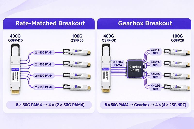
Four examples make the rule concrete:
- 100G QSFP28 to 4×25G SFP28: Matched. Four 25G NRZ parent lanes are assigned to four separate 25G NRZ child links.
- 400G QSFP-DD to 2×200G QSFP56: Matched. Eight 50G PAM4 lanes are divided into two groups of four 50G PAM4 lanes.
- 400G QSFP-DD to 4×100G QSFP56: Matched. Eight 50G PAM4 lanes are divided into four groups of two 50G PAM4 lanes.
- 400G QSFP-DD to 4×100G QSFP28: Not matched when the child ports use four 25G NRZ lanes. Use an active breakout cable with an appropriate integrated gearbox.
“Active DAC” is a label that can cause confusion. Vendors may use it to describe ACC (analog redriver or signal conditioning), AEC (active electrical cable with retiming), or active cables with integrated gearbox functionality. These technologies do not provide identical capabilities. Ask which chip is inside, what signal processing or conversion it performs, and whether the switch supports the resulting lane configuration.
Breakout DAC Reach and Compatibility
Reach: Shorter at Higher Speeds
Passive breakout DAC reach follows the same electrical principles as straight-through DAC reach. Higher lane rates and thinner conductors generally reduce the available transmission distance. Breakout assemblies also introduce additional connector and mechanical considerations at the split, so the complete assembly should be qualified rather than assuming that it will match the reach of a straight-through DAC with the same parent connector.
| Configuration | Typical passive reach | Notes |
| 40G to 4×10G | 0.5–5 m (up to 7 m for some 26 AWG products) | Legacy 10G fan-out |
| 100G to 4×25G | 0.5–3 m (up to 5 m for some 26 AWG products) | Common breakout |
| 200G to 2×100G or 4×50G | 0.5–3 m | PAM4 |
| 400G to 2×200G or 4×100G QSFP56 | 0.5–3 m | 26 AWG may be required for some 3 m products |
| 400G to 8×50G | 0.5–1 m | Thin child legs |
| 800G to 2×400G or 4×200G | 0.5–2 m | In-rack connections |
| 1.6T to 2×800G or 4×400G | 0.5–1 m | Early-generation and platform-qualified deployments |
These are representative product ranges, not guaranteed limits for every cable or switch. Always check the manufacturer’s specifications and the host platform’s cable qualification requirements.
Active breakout can extend reach beyond passive DAC, but the available distance depends on the technology and product design. Typical product ranges include ACC at approximately 3–5 m, AEC at approximately 5–7 m, and AOC at approximately 5–100 m. The exact limit depends on the host SerDes, cable construction, signal-processing architecture, and operating temperature. AEC and ACC reach figures should not be treated as interchangeable.
For the full speed-by-speed reach analysis, see DAC cable distance limits.
Compatibility: Fit Is Not Support
MSA compliance defines mechanical, electrical, and management-interface requirements, but it does not guarantee compatibility with every switch platform or firmware version. A cable can physically fit into a port cage and still be rejected because of unsupported vendor coding, speed encoding, cable class, or breakout mode.
Check four things before ordering: the parent cage, the child cage, the lane configuration, and vendor compatibility.
QSFP-DD ports are designed to support backward-compatible QSFP28 modules in supported configurations, but this does not mean that every QSFP-DD cable works in a QSFP28 port. OSFP and QSFP-DD are mechanically different and are not directly interchangeable.
SFP+ and SFP28 share the same basic mating interface. Some SFP28 DACs support backward compatibility with SFP+ ports at 10G, but actual compatibility depends on the cable design, EEPROM coding, and host vendor qualification. Do not assume that every SFP28 cable will work in an SFP+ port.
Switch Support and Configuration
The parent port must support breakout, and the network operating system must be configured to split it. Plugging in the cable alone is not enough. The available breakout ratios and configuration procedures depend on the switch model, ASIC, port group, and software version.
On Cisco NX-OS and Arista EOS, the parent port may remain a single high-speed interface until the supported breakout configuration is applied. However, whether a module or switch reload is required depends on the platform and breakout method. Module-level breakout on some Cisco platforms requires a reload, while supported per-port dynamic breakout configurations may not.
Port groups are the second constraint. Splitting one port can disable a neighboring port because the SerDes lanes are shared. Check the platform’s port map before designing the fan-out. Some platforms require adjacent ports to be disabled, and ports outside supported groups cannot be split. The available ratios are determined by the ASIC and platform architecture.
Child ports receive new interface IDs. VLAN, MTU, ACL, and QoS settings on the parent port may not automatically carry over to the new child interfaces. Plan to verify and configure each child interface individually.
Representative commands, to be verified against your platform and OS version:
- Cisco NX-OS: interface breakout module 1 port 49 map 25g-4x
- Arista EOS: interface Ethernet1, then speed forced 4x25g
- Cumulus Linux / NVUE: nv set interface swp1 breakout 4x25G
- SONiC: config interface breakout Ethernet0 4x25G[10G]
- Mellanox Onyx: interface ethernet 1/1 module-type qsfp-split-4
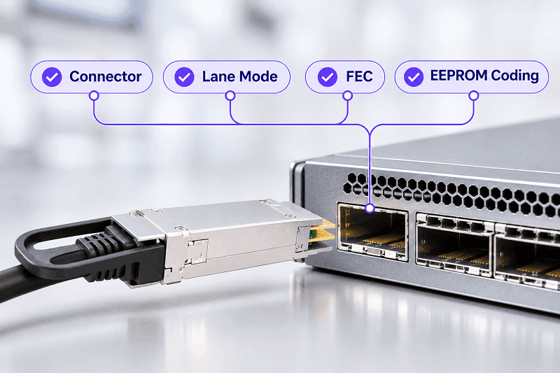
FEC is the third constraint. Copper runs longer than 2 m need RS-FEC on 25G and 50G lanes. 50G-per-lane PAM4 uses KP4 FEC. FC-FEC is lower latency but weaker.
The cable class (CA-N, CA-S, CA-L) is encoded in the EEPROM and must match the switch’s FEC setting. A mismatch can keep the link down or cause flapping under load. The NVIDIA Cumulus port-attribute documentation explains how breakout, FEC, and cable class interact on one common platform.
Breakout DAC vs Breakout AOC vs AEC
Breakout is available in four copper and optical forms. The choice is reach and power.
| Type | Reach | Power per end | Best use |
| Passive DAC breakout | 0.5–3 m | under 0.1 W | in-rack, rate-matched |
| ACC breakout | 3–5 m | 0.5–1.5 W | short reach extension |
| AEC breakout | 5–7 m | 4–5 W at 400G; 10–13 W at 800G | adjacent rack, gearbox cases |
| AOC breakout | 5–100 m | 2–4 W | cross-row, longer runs |
Use passive DAC breakout for in-rack links where the lane rates match. Use AEC when you need 2–4 more meters or a gearbox. Use AOC when the run leaves the row. Don’t use a passive DAC to solve a rate mismatch; it can’t convert modulation.
For the full comparison, see passive vs active DAC cable and DAC vs AOC cable. The broader QSFP breakout cable guide covers AOC and optical fanout architectures outside this copper-focused article.
How to Specify a Breakout DAC Cable
Seven checks turn a design into a part number:
- Parent port: form factor, lane count, and supported breakout ratios.
- Child port: form factor and speed.
- Rate matching: same lane rate and modulation? If not, specify an active gearbox or AEC.
- Length and AWG: measure the routed path, add 10–20% slack, and pick 30 AWG for short runs or 26–28 AWG for longer ones.
- Cable type: passive DAC, ACC, or AEC.
- Coding and class: vendor code, cable class, FEC.
- Labeling: leg numbers and lane map.
Common mistakes and their fixes:
| Mistake | Result | Fix |
| Matching speed but not cage | Cable will not seat | Confirm parent and child form factors |
| Assuming any port splits | No link or only one leg | Check port group and breakout support |
| Buying passive 400G to 4×100G for QSFP28 NRZ | high BER or no link | use active gearbox/AEC or 50G-PAM4 child ports |
| Forgetting breakout mode | only lane 1 links | Configure and save the split |
| 30 AWG at 3 m for 400G | link flaps | Use 26 AWG or shorten the run |
| FEC mismatch | Dark link or errors | Match RS-FEC/KP4 and cable class |
| Wrong EEPROM coding | unsupported module | Specify vendor code |
Breakout DAC Cable FAQ
What is a breakout DAC cable?
A breakout DAC cable connects one multi-lane port to two, four, or eight lower-speed ports. It distributes the parent port’s electrical lanes instead of adding bandwidth. The parent port must support the required breakout mode, and the electrical lane rates and modulation formats must be compatible for a passive cable to work.
What is the difference between a breakout DAC and a straight-through DAC?
A straight-through DAC is a 1:1 connection: one connector to one connector. A breakout DAC is a 1:2, 1:4, or 1:8 connection: one high-speed connector to multiple lower-speed connectors. Both use copper twinax construction, but breakout DACs have different connector combinations and internal lane mappings.
Can any QSFP port use a breakout cable?
No. The switch ASIC, physical port group, and network operating system must support the required breakout configuration. Ports outside the supported groups cannot be split, and the available ratios are platform-dependent. Splitting one port may also disable a neighboring port.
Does a breakout DAC cable need configuration?
Yes. The parent port must be placed in breakout mode, and the resulting child interfaces must be configured and verified for their supported speed, FEC, VLAN, and MTU settings. On some platforms, module-level breakout requires a reload; other platforms support dynamic per-port configuration without a full reload. Plugging in the cable alone does not necessarily create the child interfaces.
How many ports can a 100G, 400G, or 800G port split into?
A 100G QSFP28 port can typically split into 4×25G or, on supported platforms, 2×50G. A 400G QSFP-DD or OSFP port can split into 2×200G, 4×100G, or 8×50G, depending on its electrical lane configuration and platform support. An 800G port can split into 2×400G, 4×200G, or 8×100G, depending on the ASIC, port group, and child interface capabilities.
What is the difference between rate-matched and gearbox breakout?
Rate-matched breakout maintains the same lane rate and modulation format on both sides, allowing a passive DAC to work without additional signal conversion. Gearbox breakout converts between different lane rates or lane counts and requires active gearbox functionality. A 400G to 4×100G QSFP28 configuration using standard 25G NRZ child interfaces is a common example.
Can I use a 400G to 4×100G passive DAC with QSFP28 ports?
Not with standard 100G QSFP28 interfaces that use four 25G NRZ lanes. The 400G QSFP-DD parent typically uses eight 50G PAM4 lanes, so the electrical signaling and lane count do not match. A passive cable cannot perform this conversion. Use an active breakout cable with an appropriate integrated gearbox, or a child interface that explicitly supports the required 50G PAM4 lane configuration.
What is CR4 vs CR8?
CR4 is a four-lane copper PHY, while CR8 is an eight-lane copper PHY. The number indicates the lane count, not the aggregate speed. For example, a 400G link can use CR4 with 100G lanes or CR8 with 50G lanes. The available breakout ratio depends on the number of electrical lanes exposed by the parent port and the capabilities of the host platform.
Is a breakout DAC the same as a DAC splitter?
The terms are sometimes used interchangeably, but a breakout DAC is not a signal splitter. Each child port receives its own assigned electrical lanes rather than a copy of the same signal. “Fan-out DAC” and “hydra cable” are also common names for this type of assembly.
Related Products:
-
 OSFP8-4QSFP112-AC4M 4m (13ft) 800G Twin-port OSFP to 4x200G QSFP112 InfiniBand NDR Breakout Active Copper Cable
$900.00
-
OSFP8-2QSFP112-AC4M 4m (13ft) 800G Twin-port OSFP to 2x400G QSFP112 InfiniBand NDR Breakout Active Copper Cable
$800.00
-
OSFP8-4QSFP112-PC1M 1m (3ft) 800G InfiniBand NDR Twin-port OSFP to 4x200G QSFP112 Passive Breakout Direct Attach Copper Cable
$165.00
-
OSFP8-2QSFP112-PC1M 1m (3ft) 800G InfiniBand NDR Twin-port OSFP to 2x400G QSFP112 Passive Breakout Direct Attach Copper Cable
$165.00
-
OSFP8-4OSFP2-PC1M 1m (3ft) 800G InfiniBand NDR Twin-port OSFP to 4x200G OSFP Breakout DAC
$295.00
-
OSFP8-4OSFP2-AC4M-FLT 4m (13ft) 800G InfiniBand NDR Twin-port OSFP to 4x200G OSFP Breakout ACC
$1100.00
-
OSFP8-2OSFP4-AC4M-FLT 4m (13ft) 800G Twin-port OSFP to 2x400G OSFP InfiniBand NDR Breakout Active Copper Cable
$800.00
-
OSFP8-2OSFP4-PC1M 1m (3ft) 800Gb Twin-port OSFP to 2x400G OSFP InfiniBand NDR Breakout Direct Attach Copper Cable
$175.00
-
QDD-2QDD-400G-PC50CM 0.5m (1.6ft) 400G QSFP-DD to 2x200G QSFP-DD Passive Direct Attach Copper Breakout Cable
$176.00
-
OSFP-4Q56-PC1M 1m (3ft) 400G Twin-port 2x200G OSFP to 4x100G QSFP56 Passive Breakout Direct Attach Copper Cable
$120.00
-
OSFP-2Q56-PC1M 1m (3ft) 400G OSFP to 2x200G QSFP56 Passive Breakout Direct Attach Cable
$99.00
-
QDD-4Q28-400G-AC1M 1m (3ft) 400G QSFP-DD to 4x100G QSFP28 PAM4 Active Breakout Direct Attach Copper Cable
$2374.00