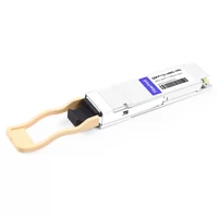
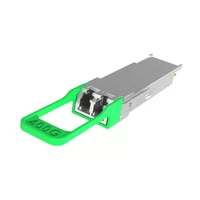
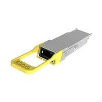
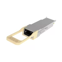
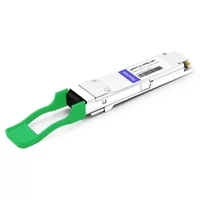
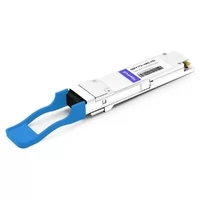
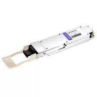
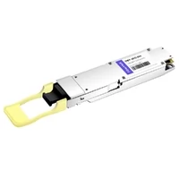
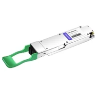
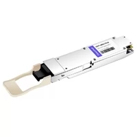
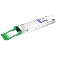
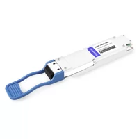
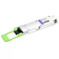
At first glance, QSFP112 and OSFP look like two competing form factors for high-speed networking. Both appear in 400G systems, both support PAM4 signaling, and both are widely used in AI and HPC infrastructure.
But treating this as a simple “QSFP112 or OSFP?” decision misses the bigger picture.
The right form factor depends on the host platform, electrical lane architecture, cooling design, required port density, and future speed roadmap. In NVIDIA AI networks, the answer also depends heavily on whether you are working with NDR 100G-PAM4 systems or newer XDR 200G-PAM4 platforms.
QSFP112 remains an important compact 400G interface, particularly on NICs and DPUs. OSFP, meanwhile, provides a larger thermal and electrical envelope and has evolved from 400G and 800G to 1.6T within the standard eight-lane OSFP architecture.
So the useful question is not simply which form factor is better.
It is:
Which form factor does the host require, what signaling generation does it support, and what bandwidth roadmap are you designing for?
This guide explains the differences that actually matter.
QSFP112 vs OSFP at a Glance
Here’s the short version, before the engineering detail.
| QSFP112 | OSFP | |
| Electrical lanes | 4 × 112G PAM4 | 8 × 50G (400G) / 8 × 100G (800G) PAM4 |
| Max speed | 400G | 800G (1.6T via OSFP-XD) |
| Module size | 18.35 × 8.5 mm (QSFP28 envelope) | 22.58 mm wide, ~13 mm high |
| Typical power | 8–12W | 12–16W (20W+ at 800G) |
| Cooling | Host cage and riding heatsink | Integrated module heatsink |
| 800G path | No | Yes |
| Backward compatible | QSFP28 / QSFP56 cages | Adapter only |
| Port density | Up to 36 per 1RU | ~32 per 1RU |
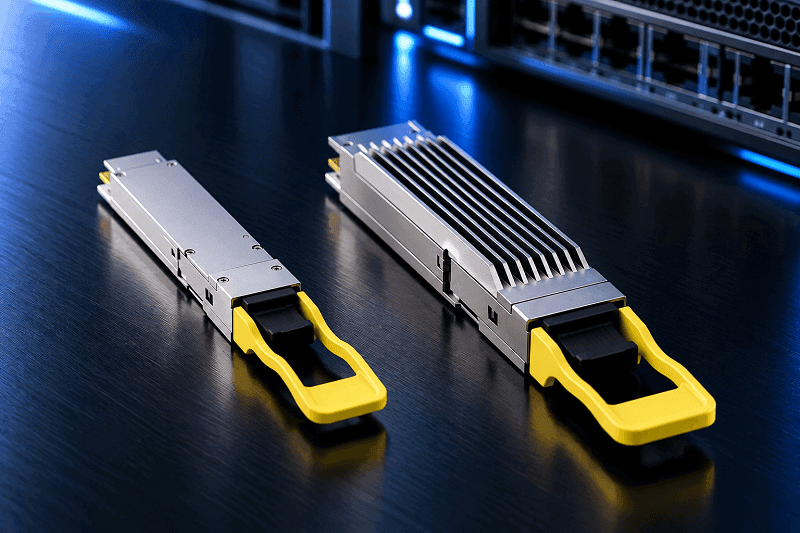
One important correction to older comparisons is that standard OSFP itself now supports 1.6T using eight 200G-per-lane electrical lanes. OSFP-XD is a separate 16-lane form factor and should not be confused with the 1.6T evolution of standard OSFP. OSFP and OSFP-XD are not mechanically interchangeable.
What QSFP112 Actually Is
QSFP112 stands for Quad Small Form-factor Pluggable 112.
Its defining feature is a four-lane high-speed electrical interface. A 400G QSFP112 host typically uses four approximately 100G-per-lane PAM4 electrical channels, giving the module a compact 4 × 100G-class architecture.
The form factor preserves the familiar QSFP mechanical envelope used by earlier QSFP generations such as QSFP28 and QSFP56.
That does not, however, mean every QSFP112 host automatically supports older modules.
Backward compatibility depends on the host SerDes, firmware, port configuration, and vendor qualification.
The QSFP112 specification includes mechanisms that allow a host to identify legacy QSFP modules and determine whether the module uses SFF-8636 or CMIS management. NVIDIA, for example, explicitly supports QSFP56 and QSFP28 backward compatibility on QSFP112-based ConnectX-7 adapters and BlueField-3 DPUs.
Why QSFP112 Is Attractive
The compact enclosure is QSFP112’s biggest practical advantage.
Four high-speed electrical lanes are sufficient for a native 400G interface, making QSFP112 well suited to:
- 400G NICs
- DPUs
- server adapters
- compact accelerator cards
- high-density 400G endpoints
NVIDIA specifically notes that QSFP112’s smaller size makes it suitable for component-dense cards such as BlueField-3.
How QSFP112 Is Cooled
It is common to see QSFP112 described as a flat-top, host-cooled form factor. That is accurate for many deployed products, particularly NVIDIA QSFP112 modules, which use a riding heatsink mounted on the adapter or DPU cage.
But this is not a universal QSFP112 rule.
The QSFP112 MSA defines multiple mechanical variants, including configurations with different thermal implementations.
So a more accurate rule is:
Cooling is implementation-specific.
For NVIDIA’s current QSFP112 products, the host typically provides the cooling solution.
The 400G Ceiling
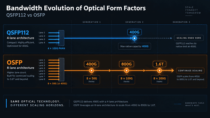
QSFP112 is fundamentally a four-lane 100G-class interface and is therefore associated with 400G operation.
Reaching 800G with four electrical lanes requires moving to approximately 200G per lane. That evolution is addressed by newer interfaces such as QSFP224 rather than by simply inserting an 800G module into a QSFP112 host.
So QSFP112 is best viewed as a highly optimized 400G generation, not as a direct 800G upgrade path.
What OSFP Actually Is
OSFP stands for Octal Small Form-factor Pluggable.
“Octal” is the key word: the standard provides eight high-speed electrical lanes.
That gives OSFP considerably more bandwidth headroom than a four-lane QSFP112 interface.
The OSFP MSA currently defines:
- 400G using 8 × 50G-class lanes
- 800G using 8 × 100G-class lanes
- 1.6T using 8 × 200G-class lanes
The exact lane mode depends on the host and module implementation.
A 400G OSFP does not necessarily use eight 50G lanes. For example, NVIDIA also uses single-port four-channel 400G OSFP modules on ConnectX adapters, while its switch-side twin-port OSFP modules use eight 100G-PAM4 electrical lanes to support two independent 400G ports.
That distinction is important.
The form factor defines the physical and electrical capability of the connector, but the actual port implementation can use only a subset of those lanes.
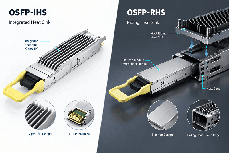
OSFP Cooling: IHS vs RHS
One of OSFP’s main advantages is thermal capacity.
However, it is incorrect to say that every OSFP module contains an integrated heatsink.
There are two important implementations.
OSFP-IHS
IHS means Integrated Heat Sink.
The heatsink is part of the module itself and may use an open-fin or closed-top design.
This configuration is common in high-power switch applications.
OSFP-RHS
RHS means Riding Heat Sink.
The module has a flat top and relies on a heatsink built into the host cage or chassis.
This is common on adapter cards and in space-constrained systems.
The OSFP MSA explicitly supports both approaches.
In NVIDIA NDR systems, for example:
- switch-side twin-port OSFP modules commonly use finned IHS designs;
- ConnectX-7 single-port OSFP modules use flat-top RHS cooling;
- QSFP112 modules used on adapters and DPUs also commonly use RHS cooling.
So thermal architecture should always be checked at the specific platform and module level.
OSFP vs QSFP112: The Five Differences That Actually Matter
1. Electrical Lane Count and Bandwidth Roadmap
QSFP112 provides four high-speed electrical lanes.
OSFP provides eight.
That difference matters more than almost anything else.
QSFP112 is naturally suited to:
4 × 100G-class PAM4 → 400G
OSFP can scale across several generations:
8 × 50G → 400G
8 × 100G → 800G
8 × 200G → 1.6T
This gives OSFP substantially more form-factor-level bandwidth headroom.
But this does not mean an older 400G or 800G OSFP switch can automatically become a 1.6T switch simply by replacing its modules.
The host must also support the required SerDes generation, connector electrical performance, PCB channel characteristics, ASIC bandwidth, firmware, power delivery, and cooling.
A 1.6T-capable OSFP module still requires a 1.6T-capable host.
That distinction is critical when planning an upgrade.
2. Mechanical Size and Thermal Capacity
QSFP112 is physically smaller.
OSFP has a larger mechanical and thermal envelope.
The larger OSFP enclosure provides more room for:
- optical engines
- DSPs
- electrical components
- heat spreading
- higher-power optics
That makes OSFP particularly attractive as module power increases at 800G and 1.6T.
QSFP112 remains attractive when physical board space is more constrained.
Neither approach is automatically better. They optimize different design constraints.
3. Front-Panel Density
QSFP112 is smaller, so it is tempting to conclude that it always provides greater switch port density.
That is too simplistic.
Actual front-panel density depends on:
- cage design
- port layout
- cooling airflow
- electrical routing
- switch ASIC architecture
- whether the cage contains one or multiple logical ports
The current OSFP MSA states that up to 36 OSFP ports can fit in a 1U front panel.
NVIDIA takes the concept further by using twin-port OSFP cages. Quantum-2 switches can use 32 physical twin-port OSFP cages to expose 64 logical 400G ports, while some Spectrum-4 platforms scale to even more logical 400G interfaces.
Therefore, comparing form factors only by the number of physical cages can be misleading.
The better metric is:
usable network bandwidth per rack unit.
4. Power Consumption
A common claim is that QSFP112 modules consume substantially less power than equivalent OSFP modules.
That is not a reliable rule.
Module power depends more on:
- optical reach
- laser technology
- DSP architecture
- optical engine design
- number of active lanes
- vendor implementation
than on the metal shell itself.
For example, NVIDIA specifies approximately 9 W maximum for both its single-port 400G QSFP112 and single-port 400G OSFP transceivers in its 100G-PAM4 product family. Its twin-port 800G OSFP transceivers are around 17 W because they contain two 400G optical engines.
So instead of budgeting:
QSFP112 = X watts
OSFP = X + 4–8 watts
the safer engineering approach is:
Use the maximum rated power of the exact module SKU you plan to deploy.
For rack-level planning, multiply that number by the deployed module count and then account for system cooling and facility PUE.
5. Upgrade Path and Host Lock-In
The physical cage is only one part of the upgrade path.
OSFP has a clear form-factor roadmap from 400G to 800G and now 1.6T.
QSFP112 is optimized for 400G; moving to 800G in a four-lane QSFP-style architecture generally means moving to a newer electrical generation such as QSFP224.
But an existing OSFP chassis should not be assumed to support every future OSFP speed.
For example:
- a host designed around 50G-per-lane SerDes cannot generate 200G-per-lane signaling;
- an 800G host may lack the electrical channel performance required by 1.6T;
- power and cooling limits may also prevent qualification of newer optics.
So OSFP provides form-factor continuity, but not guaranteed chassis-level speed upgrades.
That is a much more useful way to think about future-proofing.
QSFP112 vs OSFP in NVIDIA AI Clusters
This is where generic form-factor comparisons often become misleading.
NVIDIA uses different connector architectures across generations and product families.
The most important distinction is between:
- NDR / 400GbE systems based on 100G-PAM4
- XDR systems based on 200G-PAM4
NVIDIA’s LinkX documentation states it plainly: QSFP112 ports are not for use in switches. Quantum-2, Quantum-X800 and Spectrum-4 all use twin-port 2×400G OSFP cages, without exception.
So in an NVIDIA AI cluster, QSFP112 shows up in exactly one place: the endpoint. It terminates at ConnectX-7 adapters with QSFP112 cages, at ConnectX-8 C8240 dual-QSFP112 cards, and at BlueField-3 DPUs, where OSFP physically never fits. The switch side is always OSFP.
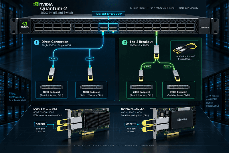
Here’s what that link looks like end to end.
| Switch side | Cable | NIC / DPU side |
| Twin-port 2×400G OSFP | Two straight fiber runs | Two single-port QSFP112 400G modules |
| Twin-port 2×400G OSFP | 1:2 splitter | Four 200G NDR200 QSFP112 ports |
A useful fact hiding in there: the QSFP112 and OSFP versions of a DR4 module have identical internals. Only the connector shell differs. The optics don’t care which cage they sit in.
The adapter-side part numbers, DPU options and bring-up order are covered in our QSFP112 NVIDIA AI cluster guide.
The rules that break builds
Marcus builds AI fabrics for a research lab in Colorado. His first 400G bring-up failed on three links and he spent a day on it. The cause wasn’t the optics. He’d mixed straight and splitter fiber on the same switch port group.
Both bit-fibers must be the same type. Both straight, or both splitter. Never mixed. It’s documented, and it’s still one of the most common ways a 400G NVIDIA build stalls on day one.
Three more traps worth knowing:
- Lane-rate mismatch. A passive 400G DAC cannot bridge an OSFP or QSFP-DD switch port running 8 × 50G PAM4 to a QSFP112 NIC port running 4 × 112G PAM4. The lane counts and rates differ. Use a module pair over fiber so each DSP handles the lane remap, or a purpose-built active cable.
- FEC mismatch. RS(544,514) KP4 forward error correction is mandatory at 100G per lane, and both ends must match. When they don’t, links flap rather than fail cleanly, which makes it hard to diagnose.
- Management version. CMIS 4.0 is the floor. CMIS 5.2 is what you want in production for per-lane SNR and extended DOM. Older firmware can misidentify a module or report garbage diagnostics.
Part numbers are another minefield. In NVIDIA’s LinkX naming, MMA means multimode and MMS means single-mode. The next digit encodes the cage: 1 for QSFP112, 4 for OSFP. Pick the wrong family and you’ve bought a switch-side module for a NIC-side cage.
For 800G-to-400G builds specifically, an active electrical cable like FiberMall’s 800G OSFP to 2×QSFP112 AEC handles the asymmetry without a module pair at each end.
When to Choose QSFP112 vs OSFP
Specs don’t make decisions. Constraints do. Here’s how the scenarios usually break down.
Choose QSFP112 when:
- You’re upgrading brownfield QSFP28 or QSFP56 infrastructure and want to reuse existing cages
- Front-panel density and per-port power are your binding constraints
- You’re building a 400G-only fabric and 800G isn’t on the roadmap
- You’re populating the NIC or DPU side of an NVIDIA fabric, where there’s no alternative
- Your environment is Cisco or Arista centric, where QSFP112 is the standard 400G interface
Choose OSFP when:
- You’re building greenfield and 800G or 1.6T sits inside your planning horizon
- Sustained high-load AI or HPC optics need module-level thermal margin
- You’re buying the switch side of an NVIDIA reference architecture
- Long-reach or high-power optics are in scope
Elena runs infrastructure for an enterprise group in Chicago. Her team faced a classic DC refresh last year: 200 racks of QSFP28 and QSFP56 already in place, and a requirement to reach 400G without touching the switch chassis.
They went QSFP112. Same cages, same fiber plant, roughly 40% less per-port power than the QSFP-DD alternative they modeled. No structural change to the racks.
A greenfield AI team in the same building made the opposite call. They bought OSFP switches because their GPU roadmap ran through 800G, and QSFP112 only on the server side where NVIDIA requires it. Two teams, one building, two different answers. Both correct.
The honest default for most 2026 builds: 400G-only and density-constrained points to QSFP112. An AI fabric with a GPU roadmap points to OSFP switches, QSFP112 NICs, and asymmetric cables in between. Mixed environments tend to be OSFP where the roadmap demands it and QSFP112 where the cages already exist.
| Scenario | Typical Choice | Reason |
| BlueField-3 400G connection | QSFP112 | NVIDIA platform requirement |
| ConnectX-7 QSFP112 version | QSFP112 | Matches host cage |
| ConnectX-7 OSFP version | OSFP | Matches host cage |
| Quantum-2 NDR switch | Twin-port OSFP | NVIDIA switch architecture |
| Spectrum-4 100G-PAM4 switch | Twin-port OSFP | NVIDIA switch architecture |
| Quantum-X800 switch | 1.6T twin-port OSFP | 200G-PAM4 XDR architecture |
| Compact 400G NIC/DPU | Often QSFP112 | Smaller form factor |
| 800G interface | OSFP or another 800G-capable form factor | Requires higher host bandwidth |
| 1.6T OSFP-capable platform | OSFP | 8 × 200G electrical architecture |
| Existing legacy QSFP infrastructure | Host-dependent | Verify actual backward compatibility |

Cost, Availability, and the 1.6T Question
Cost comparisons between QSFP112 and OSFP need context.
The price of a transceiver depends heavily on:
- SR4 vs DR4 vs FR4 vs LR4;
- multimode vs single-mode;
- reach;
- DSP architecture;
- brand compatibility;
- coding and qualification requirements;
- order volume.
Current FiberMall listings, for example, show substantial price variation even within the same form factor and speed, making a universal “QSFP112 is cheaper than OSFP” rule unreliable.
The better comparison is:
total deployed cost for the required host, reach, power, cooling, and upgrade plan.
For a 400G project, module cost may dominate the short-term purchasing decision.
For an 800G or 1.6T architecture, however, the host platform becomes much more important.
FAQ
Is QSFP112 the same as OSFP?
No. QSFP112 is a four-lane QSFP-family form factor commonly used for 400G with approximately 100G-per-lane PAM4 signaling.
OSFP is a larger eight-lane form factor that supports multiple electrical generations and currently scales to 1.6T.
They are mechanically different and are not interchangeable.
Can a QSFP112 module fit in an OSFP port?
No. A QSFP112 module cannot be inserted directly into an OSFP cage.
The connector mechanics and electrical interfaces are different.
If the two systems need to communicate, use an appropriate cable or optical link designed for the two host interfaces.
Does QSFP112 support 800G?
QSFP112 itself is associated with a four-lane 400G architecture.
A four-lane 800G interface requires a newer approximately 200G-per-lane electrical generation, such as QSFP224.
So an existing QSFP112 host should not be assumed to support 800G simply by changing the module.
Does OSFP Support 1.6T?
Yes. The current OSFP MSA defines 1.6T operation using eight 200G-per-lane electrical channels.
However, both the module and host platform must support that electrical generation.
Is OSFP-XD Required for 1.6T?
No. Standard OSFP itself supports 1.6T.
OSFP-XD is a separate 16-lane form factor designed for even greater aggregate density and bandwidth.
OSFP and OSFP-XD are not mechanically interchangeable.
Which Has Better Port Density?
There is no universal winner.
QSFP112 is physically smaller, which can help in space-constrained designs.
OSFP is larger, but modern switch architectures can use dense OSFP layouts and even twin-port implementations.
For example, the OSFP MSA supports up to 36 physical OSFP ports in a 1U front panel, while NVIDIA twin-port OSFP switches can expose two logical network ports per cage.
Compare actual switch port density rather than form-factor dimensions alone.
Is QSFP112 Lower Power Than OSFP?
Not necessarily.
Power consumption is primarily determined by the optical and electrical implementation rather than by the shell alone.
NVIDIA specifies similar maximum power for comparable single-port 400G QSFP112 and OSFP transceivers in its 100G-PAM4 product family.
Always compare the exact module SKUs.
Can an OSFP Switch Connect to a QSFP112 NIC?
Yes, in supported architectures.
This is common in NVIDIA NDR systems.
A twin-port OSFP switch interface can connect to QSFP112 endpoint ports using appropriately designed DACs, ACCs, AOCs, or optical transceivers and fiber.
But the lane rates and breakout configuration must match.
Can QSFP112 Use QSFP56 or QSFP28 Modules?
Sometimes.
The physical QSFP family enables this possibility, but backward compatibility depends on the host.
NVIDIA explicitly supports QSFP56 and QSFP28 devices in QSFP112-based ConnectX-7 adapters and BlueField-3 DPUs.
For other platforms, check the vendor’s hardware and software compatibility matrix.
Conclusion
The QSFP112 vs OSFP comparison is not simply a contest between a smaller and a larger transceiver.
The real differences are architectural.
QSFP112 provides a compact four-lane interface optimized for 400G. It is particularly useful on NICs, DPUs, and other space-constrained endpoints. On supported hosts, it can also provide useful backward compatibility with earlier QSFP generations.
OSFP provides eight electrical lanes, greater thermal headroom, and a broader bandwidth roadmap. The current OSFP specification supports 400G, 800G, and 1.6T signaling generations.
But form factor alone does not determine system capability.
A 1.6T OSFP module still requires a 1.6T-capable host.
The same principle applies to AI clusters.
In NVIDIA NDR systems, twin-port OSFP is the dominant switch-side interface, while endpoint devices may use QSFP112 or single-port OSFP depending on the ConnectX or BlueField platform.
In newer XDR systems, NVIDIA moves the switch-side OSFP architecture to 1.6T twin-port connectivity and introduces 800G-class endpoint connectivity.
So before ordering any module or cable, verify five things:
- the host cage;
- the number of electrical lanes;
- the electrical lane rate;
- the required breakout mode;
- the host vendor’s supported module and cable list.
That is far more reliable than choosing a transceiver based only on whether the label says “400G,” “800G,” QSFP112, or OSFP.
Buy for the host architecture you actually have — and the signaling generation it actually supports.
Related Products:
-
 FiberMall QSFP112-400G-VR4 Compatible 400G QSFP112 VR4 PAM4 850nm 50m MTP/MPO-12 OM4 FEC Optical Transceiver Module
$385.00
FiberMall QSFP112-400G-VR4 Compatible 400G QSFP112 VR4 PAM4 850nm 50m MTP/MPO-12 OM4 FEC Optical Transceiver Module
$385.00
-
LQSFP112-400G-FR4 400G LPO QSFP112 FR4 PAM4 CWDM 2km Duplex LC SMF FEC Optical Transceiver Module
$1350.00
-
LQSFP112-400G-DR4 400G LPO QSFP112 DR4 PAM4 1310nm 500m MTP/MPO-12 with KP4 FEC Optical Transceiver Module
$1200.00
-
LQSFP112-400G-SR4 400G LPO QSFP112 SR4 PAM4 850nm 50m MTP/MPO-12 OM3 FEC Optical Transceiver Module
$800.00
-
QSFP112-400G-LR4 400G QSFP112 LR4 PAM4 CWDM 10km Duplex LC SMF FEC Optical Transceiver Module
$1000.00
-
QSFP112-400G-FR4 400G QSFP112 FR4 PAM4 CWDM 2km Duplex LC SMF FEC Optical Transceiver Module
$600.00
-
QSFP112-400G-FR1 4x100G QSFP112 FR1 PAM4 1310nm 2km MTP/MPO-12 SMF FEC Optical Transceiver Module
$800.00
-
QSFP112-400G-DR4 400G QSFP112 DR4 PAM4 1310nm 500m MTP/MPO-12 with KP4 FEC Optical Transceiver Module
$500.00
-
QSFP112-400G-SR4 400G QSFP112 SR4 PAM4 850nm 100m MTP/MPO-12 OM3 FEC Optical Transceiver Module
$400.00
-
OSFP-400G-SR8 400G SR8 OSFP PAM4 850nm MTP/MPO-16 100m OM3 MMF FEC Optical Transceiver Module
$299.00
-
OSFP-400G-DR4 400G OSFP DR4 PAM4 1310nm MTP/MPO-12 500m SMF FEC Optical Transceiver Module
$800.00
-
OSFP-400G-FR4 400G FR4 OSFP PAM4 CWDM4 2km LC SMF FEC Optical Transceiver Module
$900.00
-
OSFP-400G-PSM8 400G PSM8 OSFP PAM4 1550nm MTP/MPO-16 300m SMF FEC Optical Transceiver Module
$800.00
-
OSFP-2x200G-FR4 2x 200G OSFP FR4 PAM4 2x CWDM4 CS 2km SMF FEC Optical Transceiver Module
$1500.00
-
OSFP-400G-LR4 400G LR4 OSFP PAM4 CWDM4 LC 10km SMF Optical Transceiver Module
$1199.00
-
OSFP-400G-DR4+ 400G OSFP DR4+ 1310nm MPO-12 2km SMF Optical Transceiver Module
$850.00